


User Manual
SUPPORT@INERTIALSENSE.COM WWW.INERTIALSENSE.COM
µINS, µAHRS, and µIMU
Product
User Manual
11/30/2017
Inertial Sense LLC
72 N 720 E
Salem, UT 84653
801-610-6771
support@inertialsense.com
www.inertialsense.com

User Manual
© 2017 Inertial Sense, LLC 2 11/30/2017
Contents
1 Overview ............................................................................................................................................................... 4
1.1 Description of differences between IMU, AHRS, INS ................................................................................... 4
2 Getting Started...................................................................................................................................................... 5
2.1 Unpacking Your Unit .................................................................................................................................... 5
2.2 Downloading the EvalTool and SDK ............................................................................................................. 5
2.3 EvalTool GUI ................................................................................................................................................. 5
2.4 Connecting To Your Unit .............................................................................................................................. 5
2.5 System LED and Solution Status ................................................................................................................... 6
2.6 Inertial Sense CLTool .................................................................................................................................... 6
2.6.1 Compiling in Linux/Mac ........................................................................................................................... 6
2.6.2 Compiling in Windows (MS Visual Studio) ............................................................................................... 7
2.6.3 Running CLTool ........................................................................................................................................ 7
2.7 Additional Development .............................................................................................................................. 8
3 Coordinate Frames ................................................................................................................................................ 9
3.1 Sensor Frame ............................................................................................................................................... 9
3.2 INS Output Frame......................................................................................................................................... 9
3.3 North-East-Down (NED) Frame .................................................................................................................... 9
3.4 Earth-Centered Earth-Fixed (ECEF) Frame ................................................................................................... 9
3.5 Translation Between Coordinate Frames ................................................................................................... 10
4 Hardware Integration ......................................................................................................................................... 11
4.1 Noise Coupling ........................................................................................................................................... 11
4.2 Vibration Isolation ...................................................................................................................................... 11
4.3 Sensitivity to Temperature Change ............................................................................................................ 11
5 SDK Library .......................................................................................................................................................... 12
5.1 Binary Protocol ........................................................................................................................................... 12
5.2 ASCII Protocol ............................................................................................................................................. 13
5.2.1 ASCII Messages ...................................................................................................................................... 14
5.3 C Binding .................................................................................................................................................... 17
5.3.1 Connecting to the Device ....................................................................................................................... 17
5.3.2 Communicating with the device ............................................................................................................ 18
5.3.3 Updating Firmware (Bootloader) ........................................................................................................... 18
5.4 C++ Binding ................................................................................................................................................ 19
6 Binary Protocol Data Sets ................................................................................................................................... 20
6.1 Configuration ............................................................................................................................................. 20
6.1.1 DID_FLASH_CONFIG ............................................................................................................................... 20
6.2 Using Com Manger to Write Data Set Parameter ...................................................................................... 20
7 System Health and Status Flags .......................................................................................................................... 21
7.1 Status Flags................................................................................................................................................. 21

User Manual
© 2017 Inertial Sense, LLC 3 11/30/2017
7.1.1 insStatus – INS Status Flags .................................................................................................................... 21
7.1.2 hdwStatus – Hardware Status Flags....................................................................................................... 21
7.1.3 Built-in test (BIT) Flags ........................................................................................................................... 22
7.2 Typical Health Monitoring .......................................................................................................................... 22
8 Magnetometer Calibration ................................................................................................................................. 24
8.1 Magnetometer Recalibration ..................................................................................................................... 24
8.1.1 External Recalibration ............................................................................................................................ 24
8.1.2 Automatic Recalibration ........................................................................................................................ 25
8.2 Magnetometer Continuous Calibration ..................................................................................................... 25
8.3 Magnetometer Calibration Settings ........................................................................................................... 25
9 Data Logging ....................................................................................................................................................... 26
9.1 Log File ....................................................................................................................................................... 26
9.1.1 Log Chunk .............................................................................................................................................. 26
9.1.2 Chunk Header ........................................................................................................................................ 26
9.1.3 Chunk Data ............................................................................................................................................ 27
9.1.4 Chunk Sub-Header ................................................................................................................................. 27
9.1.5 Data Set Header ..................................................................................................................................... 27
9.2 Data Loggers ............................................................................................................................................... 27
9.3 EvalTool Data Logging ................................................................................................................................ 27
10 Plotting Log Files ................................................................................................................................................. 29
10.1 Matlab (*.dat) ............................................................................................................................................ 29
10.2 Python (*.sdat) ........................................................................................................................................... 29
10.3 Excel (*.csv) ................................................................................................................................................ 29
11 Troubleshooting .................................................................................................................................................. 30

User Manual
© 2017 Inertial Sense, LLC 4 11/30/2017
1 Overview
The µINS GPS aided Inertial Navigation System, µAHRS Attitude Heading Reference System, and the µIMU Inertial
Measurement Unit monitor many different types of measurements including rotation, acceleration, GPS position,
magnetic flux density, pressure and velocity. The Inertial Sense SDK provides a software interface to allow
communication with the device including setting configuration options, retrieving specific data, and listening for
data broadcasts.
For example, you could configure the device to broadcast the current latitude, longitude, and altitude as well as
the heading and velocity at up to 500Hz. This manual will cover the underlying protocol and message format
(binary and ASCII) involved in communicating with the device, along with a C, C++ and C# binding.
1.1 Description of differences between IMU, AHRS, INS
The μIMU™ is a miniature calibrated sensor module consisting of an Inertial Measurement Unit (IMU),
magnetometer, barometer, and L1 GPS (GNSS) receiver. Data out includes angular rate, linear acceleration,
magnetic field, barometric altitude, and GPS WGS84 geo-position. All systems include a comprehensive sensor
calibration for bias, scale-factor, and cross-axis alignment, minimizing manufacturing variation and maximizing
system performance.
The μAHRS™ is an Attitude Heading Reference System (AHRS) that includes all functionality of the μIMU™ and
fuses IMU and magnetometer data to estimate roll, pitch, and heading.
The μINS™ is a GPS (GNSS) aided inertial navigation system (GPS-INS) module that includes all functionality of the
μIMU™ and provides orientation, velocity, and position. Sensor data from MEMs gyros, accelerometers,
magnetometers, barometric pressure, and GPS/GNSS is fused to provide optimal measurement estimation.

User Manual
© 2017 Inertial Sense, LLC 5 11/30/2017
2 Getting Started
This section provides instructions on how to quickly set up the µINS, µAHRS, or µIMU and start collecting data.
2.1 Unpacking Your Unit
Most customers will choose to purchase the EVB (Evaluation Board) and Semi-Rugged Case with their µINS, µAHRS,
or µIMU. The EVB allows for multiple types of serial connections to be made with the µINS, µAHRS, or µIMU
including RS232, RS485, RS422, TTL, and USB. (Coming soon CAN bus, SPI and I2C.) A FTDI USB to serial converter
on the EVB connects the EVB USB port to a serial port on the µINS, µAHRS, or µIMU.
2.2 Downloading the EvalTool and SDK
The EvalTool and CLTool (part of the SDK) are provided to help users quickly evaluate and integrate the µINS,
µAHRS, and µIMU.
You can visit the Inertial Sense website’s Resources page at https://inertialsense.com/resources to get access to
the source code downloads (EvalTool and SDK). The EvalTool Windows installer comes with the SDK and firmware.
The installer will automatically save the EvalTool in C:\Program Files\Inertial Sense, and a desktop shortcut will also
be created. The SDK and firmware will be saved in C:\Users\UserName\Documents\Inertial Sense. The SDK and
firmware can also be downloaded individually and saved into a directory of your choosing.
2.3 EvalTool GUI
The EvalTool is a graphical Windows-based desktop program that allows you to explore and test functionality of
the Inertial Sense products in real-time. It has scrolling plots, 3D model representation, table views of all data, a
data logger, and a firmware updating interface for the µINS, µAHRS, or µIMU. The EvalTool can simultaneously
interface with multiple Inertial Sense devices.
In the EvalTool under the Settings tab, make sure to select the Auto Refresh check box next to the COM port
connected to the µINS, µAHRS, or µIMU. Once the correct COM port is selected data will immediately begin to be
received.
2.4 Connecting To Your Unit
A serial port is the standard interface on the µINS, µAHRS, and µIMU. The EVB provides an optional RS232 and
USB interface to the serial ports. When the EVB USB port is connected to a PC, it will appear as a virtual com port
to Ser1. Both the EvalTool and the InertialSenseCLTool project connect using a serial port. The baud rate can be
configured by modifying the ser0BaudRate or ser1BaudRate fields of DID_FLASH_CONFIG, which can be accessed
in the DataSets tab of the EvalTool.
Table 1 – Serial Communication Ports
Serial
Port
µINS, µAHRS,
µIMU Pins
Interface Type
EVB Pins
Interface Type
Ser 0 18,19 (Rx,Tx)
TTL
H4: 3,4 (Rx,Tx)
TTL, RS232,
USB (default)
Ser 1 6,7 (Rx,Tx)
TTL
H6: 4,5 (Rx,Tx)
TTL, RS232,
RS485/RS422, USB
EVB USB connection toggles between Ser0 and Ser1 by setting “USB” jumpers.

User Manual
© 2017 Inertial Sense, LLC 6 11/30/2017
2.5 System LED and Solution Status
Each unit is equipped with an RGB LED on the top face. This LED indicates the unit’s system and solution status and
can pulse various combinations of the behaviors listed below.
LED Behavior
Status
Description
White
1
Solution Aligning
The solution is aligning on startup.
Cyan
2
Solution Alignment
Complete
The solution has aligned but insufficient dynamics have
been completed for the variance to reach nominal
conditions.
Green
3
Solution Good – NAV
The solution is in Navigation mode and state estimate is
good.
Blue
5
Solution Good – AHRS
The solution is in AHRS mode and state estimate is good.
There is no valid position or velocity data from GPS or
other aiding sensor. Only the attitude states are
estimated.
Orange
4 6 Solution High Variance
The solution is in Navigation or AHRS mode but variance
(uncertainty) is high. This may be caused by excessive
sensor noise such as vibration, magnetic interference, or
poor GPS visibility or multipath errors. See
DID_INL2_VARIANCE.
Purple
Magnetometer
Recalibration
The system is collecting new magnetometer calibration
data and requires rotation.
Purple fast blink
Firmware Upload
The bootloader is uploading the embedded firmware.
Orange fast blink
Firmware Verification
The bootloader is verifying the embedded firmware.
Red
Bootloader Failure
The bootloader has experienced a failure on startup.
Can combine with behaviors above
Red/purple pulse every 1s
RTK Base Data Received
The system is receiving RTK base station data.
Purple pulse every 1s
RTK Fix Status
The GPS has valid RTK fix and high precision positioning.
Red pulse every 1s
GPS PPS Sync
The system has received and synchronized local time to
UTC time using the GPS PPS signal.
2.6 Inertial Sense CLTool
The Inertial Sense CLTool is a command line utility that can be used to read and display data, update firmware, and
log data from Inertial Sense products. Additionally, CLTool serves as example source code that demonstrates
integration of the Inertial Sense SDK into your own source code. The CLTool can be compiled in Linux, Mac,
Windows and embedded platforms.
2.6.1 Compiling in Linux/Mac
1. Create build directory.
$ cd InertialSenseCLTool
$ mkdir build
2. Run cmake from within build directory.
$ cd build

User Manual
© 2017 Inertial Sense, LLC 7 11/30/2017
$ cmake ..
3. Compile using make.
$ make
4. Add current user to the "dialout" group in order to read and write to the USB serial communication ports:
$ sudousermod -a -G dialout $USER
$ sudousermod -a -G plugdev $USER
(reboot computer)
5. Run executable
$ ./bin/cltool
2.6.2 Compiling in Windows (MS Visual Studio)
1. Open Visual Studio solution file (<Path to SDK>/InertialSenseCLTool/VS_project/InertialSenseCLTool.sln).
2. Build (F7).
2.6.3 Running CLTool
The Windows executable is “cltool.exe” and the Linux/Mac executable is “cltool”.
2.6.3.1 Command Line Options
Run the CLTool with the “-h” option to display the command line options.
$ ./bin/cltool -h
DESCRIPTION
Command line utility for communicating, logging, and updating
firmware with Inertial Sense product line.
EXAMPLES
cltool -c=/dev/ttyS2 # stream post processing data (PPD) with INS2 (default)
cltool -c=/dev/ttyS2 -lon -lts=1 # logging to timestamp directory, stream PPD + INS2 data
cltool -c=/dev/ttyS2 -lon -msgSol=3 # logging, stream PPD + INS3 data
cltool -c=/dev/ttyS2 -baud=115200 -msgINS2 -msgGPS -msgBaro # stream multiple data sets at 115200 baud rate
cltool -c=/dev/ttyS2 -msgSol=0 # disable solution stream
cltool -rp=logs/20170117_222549 # replay log files from a folder
cltool -c=/dev/ttyS2 -b= fw/IS_uINS-3.hex # bootload firmware
cltool -c=* -baud=921600 # 921600 mbps baudrate on all serial ports
OPTIONS (General)
-h --help display this help menu
-c=COM_PORT select the serial port. Set COM_PORT to "*" for all ports and "*4"
to use only the first four ports. Not specifying this parameter is same as “-c=*”
-baud=BAUDRATE set serial port baudrate. Options: 115200, 230400, 460800, 921600, 3000000 (default)
-b=FILEPATH bootload firmware using .hex file FILEPATH
-q quite mode, no display
-s scroll displayed messages to show history
-stats display statistics of data received
OPTIONS (Solution Streaming)
-msgSol[n] Post Process Data (PPD) = DID_GPS + DID_MAGNETOMETER1 + DID_MAGNETOMETER2 +
DID_BAROMETER + DID_FLASH_CONFIG. Use -msgSol0 to disable solution streaming.
n= 1: PPD + DID_DUAL_IMU + DID_INS1
n= 2: PPD + DID_DUAL_IMU + DID_INS2 (recommended default)
n= 3: PPD + DID_DUAL_IMU + DID_INS3
n= 4: PPD + DID_DUAL_IMU + DID_INS4
n=11: PPD + DID_DELTA_THETA_VEL + DID_INS1
n=12: PPD + DID_DELTA_THETA_VEL + DID_INS2
n=13: PPD + DID_DELTA_THETA_VEL + DID_INS3
n=14: PPD + DID_DELTA_THETA_VEL + DID_INS4
INS output only without PPD
n=21: DID_INS1, n=22: DID_INS2, n=23: DID_INS3, n=24: DID_INS4
OPTIONS (Message Streaming)
-msgINS[n] message DID_INS_[n], where [n] = 1, 2, 3 or 4 (without brackets)
-msgIMU[n] message DID_IMU_[n], where [n] = 1 or 2 (without brackets)
-msgDualIMU message DID_DUAL_IMU
-msgDThetaVel message DID_DELTA_THETA_VEL
-msgMag[n] message DID_MAGNETOMETER_[n], where [n] = 1 or 2 (without brackets)
-msgBaro message DID_BAROMETER
-msgGPS message DID_GPS
-msgSensors message DID_SYS_SENSORS
OPTIONS (Logging to file, disabled by default)
User Manual
© 2017 Inertial Sense, LLC 8 11/30/2017
-lon enable logging
-lp=PATH log data to path (default: IS_logs)
-lms=PERCENT log max space in percent of free space (default: 0.5)
-lmf=BYTES log max file size in bytes (default: 5242880)
-lmm=BYTES log max memory in bytes (default: 131072)
-lts=0 log sub folder, 0 or blank for none, 1 for timestamp, else use as is
-r replay data log from default path
-rp=PATH replay data log from PATH
-rs=SPEED replay data log at x SPEED
OPTIONS (Read or write flash configuration)
-flashConfig=. - read flash config and display.
-flashConfig=key=value|key=value - set key / value pairs in flash config.
OPTIONS (Client / server)
-svr=connectionInfo, used to retreive external data and send to the uINS. Examples:
For retrieving RTCM3 data: -svr=RTCM3:192.168.1.100:7777:url:user:password - url, user and password optional.
For retrieving SERIAL data: -svr=RTCM3:SERIAL:COM9:57600 (port, baud).
For retrieving InertialSense data: -svr=IS:192.168.1.100:7777 - no url, user or password.
For retrieving UBLOX data: -svr=UBLOX:192.168.1.100:7777 - no url, user or password.
-host=ipAndPort, used to host a tcp/ip InertialSense server.
Example: -host=:7777 or -host=192.168.1.43:7777. The ip address part is optional.
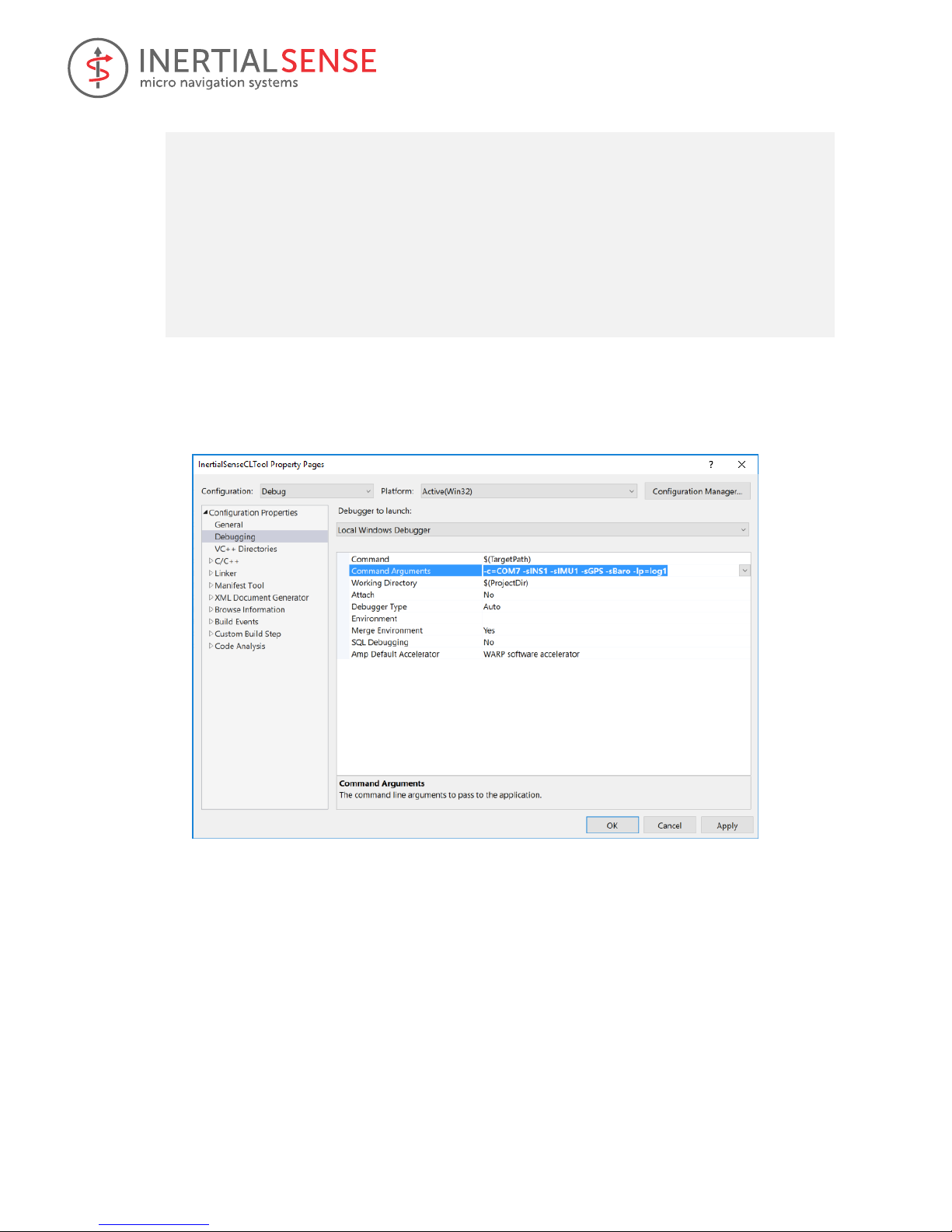
2.6.3.2 Command Line Options in MS Visual Studio
When using MS Visual Studio IDE, command line arguments can be supplied by right clicking the project in the
solution explorer and then selecting Configuration Properties -> Debugging -> Command Arguments (see image
below).
2.7 Additional Development
The basic methods of interfacing with the µINS, µAHRS, and µIMU have been shown. Additional development, such
as configuring the system, calibrating the magnetometer and logging data, can be taken and instructions constitute
the remainder of this manual.
User Manual
© 2017 Inertial Sense, LLC 9 11/30/2017
3 Coordinate Frames
In this manual, coordinate frame systems are simply referred to as frames. This section is to assist the developer in
choosing and implementing the appropriate coordinate frames for their respective application. It should be noted
that the following frames are in relation to the uINS itself.
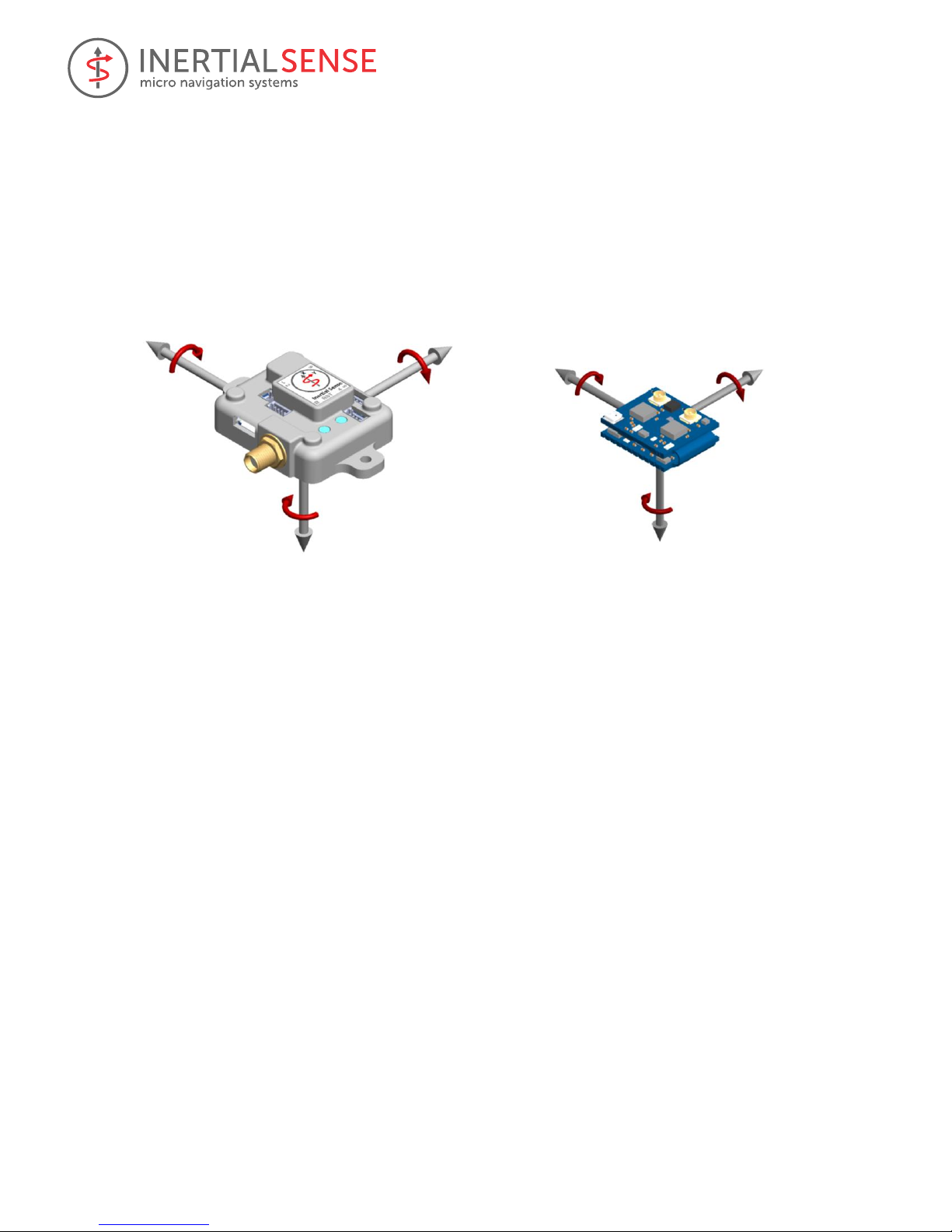
3.1 Sensor Frame
IMU, magnetometer, and INS velocity data are in the Sensor Coordinate Frame, or Sensor Frame, and are
identified by the X, Y, and Z axes labeled on the hardware. The z-axis is positive down into the image.
3.2 INS Output Frame
The INS output data (DID_INS_1, DID_INS_2, DID_INS_3) is in the INS Output Frame. Translation from Sensor
Frame to INS Output Frame is defined as:
1. Sensor Frame → Intermediate Output Frame by rotation of DID_FLASH_CONFIG.insRotation euler angles
(in order of heading, pitch, roll angle) In radians.
2. Intermediate Output Frame → INS Output Frame: Offset by DID_FLASH_CONFIG.insOffset in meters.
If DID_FLASH_CONFIG.insRotation and DID_FLASH_CONFIG.insOffset are zero, the Sensor Frame and the INS
Output Frame are the same.
3.3 North-East-Down (NED) Frame
Position estimates can be output in the North-East-Down (NED) coordinate frame defined as follows:
• Right-handed, Cartesian, non-inertial, geodetic frame with origin located at the surface of Earth (WGS84
ellipsoid).
• Positive X-axis points towards North, tangent to WGS84 ellipsoid.
• Positive Y-axis points towards East, tangent to WGS84 ellipsoid.
• Positive Z-axis points down into the ground completing the right-handed system.
3.4 Earth-Centered Earth-Fixed (ECEF) Frame
The Earth-Centered Earth-Fixed (ECEF) frame is defined as follows:
• Right-handed, Cartesian, non-inertial frame with origin located at the center of Earth.
• Fixed to and rotates with Earth.
• Positive X-axis aligns with the WGS84 X-axis, which aligns with the International Earth Rotation and
Reference Systems Service (IERS) Prime Meridian.
X
+Roll
Z
+Yaw
Y
+Pitch
X
+Roll
Z
+Yaw
Y
+Pitch

User Manual
© 2017 Inertial Sense, LLC 10 11/30/2017
• Positive Z-axis aligns with the WGS84 Z-axis, which aligns with the IERS Reference Pole (IRP) that points
towards the North Pole.
• Positive Y-axis aligns with the WGS84 Y-axis, completing the right-handed system.
3.5 Translation Between Coordinate Frames
This section is intended to be an example of how to rotate between frames using methods defined within the SDK.
For Example, converting body frame to NED frame is implemented by:
quatRot(vel_ned, DID_INS_2.qn2b, DID_INS_2.uvw);

User Manual
© 2017 Inertial Sense, LLC 11 11/30/2017
4 Hardware Integration
4.1 Noise Coupling
To ensure that noise is not being coupled into the Inertial Sense sensor module designed into your product, it can
be compared with a stock EVB demo unit to compare noise figures. This is done by using the following steps. If
both steps pass, you can know there is no noise being coupled into the module. You may optionally connect more
than one sensor module to the EvalTool at a time to compare noise.
1. Evaluate the IMU sensor - Make sure the unit is stationary (on a table or non-moving surface) and not
seeing any vibrations. Watch the standard deviation column labeled "σ" in the Sensors tab of the
EvalTool. This shows the noise level over the past 5 seconds, which means the device needs to be
completely stable for 5 seconds to be accurate. Compare this figure between your integrated sensor
module and EVB demo unit.
2. Evaluate GPS sensitivity – In clear view of the sky, monitor the satellite signal strength through the
"DID_GPS_CNO" item in the "Data Sets" tab of the EvalTool. See that the strongest (largest) CNO values
are roughly the same between your integrated sensor module and the EVB demo unit.
4.2 Vibration Isolation
The system accuracy will degrade in the presence of constant vibrations that exceed 3 g of acceleration. Adding
vibration isolation to the mount may be necessary to reduce the vibrations seen by the product.
4.3 Sensitivity to Temperature Change
The system is designed to compensate for the effects of temperature drift, which can be found in typical
operation. However, rapid hardware temperature changes can result in degraded accuracy of the IMU calibration,
GPS position, and INS estimate. Rapid temperature change can be caused by direct exposure to wind, sun, and
other elements.

User Manual
© 2017 Inertial Sense, LLC 12 11/30/2017
5 SDK Library
This section describes the InertialSense Software Development Kit (SDK) used to communicate and interface with
the Inertial Sense products.
5.1 Binary Protocol
The Inertial Sense binary protocol provides the most efficient way to communicate with the µINS, µAHRS, and
µIMU. This section is provided to detail the packet and data structures format used in this binary protocol. You do
not need to be concerned with this section if you are using the Com Manager built-in binary interface, discussed
later in this manual. The µINS, µAHRS, and µIMU communicate using the following packet formatting:
Figure 1 - Packet Structure
Packet Header (4 bytes)
1 byte – packet start byte (0xFF)
1 byte – packet identifier, determines the format of packet data
1 byte – packet counter (for retries)
1 byte – flags, ePktHdrFlags enum
// in com_manager.h:
enum ePktHdrFlags
{
// bit set for little endian, bit cleared for big endian
CM_PKT_FLAGS_LITTLE_ENDIAN = 0x01,
// has any valid packet been received
CM_PKT_FLAGS_RX_VALID_DATA = 0x02,
// multi-packet data set
CM_PKT_FLAGS_MORE_DATA_AVAILABLE = 0x04,
// Allow for arbitrary length in bytes of data, not necessarily multiple of 4.
Don't auto-swap bytes for endianness
CM_PKT_FLAGS_RAW_DATA_NO_SWAP = 0x08,
// Checksum is the new 24 bit algorithm instead of the old 16 bit algorithm
CM_PKT_FLAGS_CHECKSUM_24_BIT = 0x10
};
Packet data (may be 0 bytes, depending on packet identifier)
Figure 2 – Packet Data Structure

User Manual
© 2017 Inertial Sense, LLC 13 11/30/2017
The format of the packet data is determined by the packet identifier. For a data packet (PID_DATA (4) or
PID_SET_DATA (5)) the first 12 bytes are always the data identifier (4 byte int), the offset into the data (4 byte int),
and the length of data (4 byte int, not including the 12 bytes or packet header / footer).
Packet footer (4 bytes)
1 byte – checksum byte A (most significant byte)
1 byte – checksum byte B (middle byte)
1 byte – checksum byte C (least significant byte)
1 byte – packet stop byte (0xFE)
The packet checksum is a 24-bit integer (little-endian) that can be created as follows:
- Start the checksum value at 0x00AAAAAA and skip the packet start byte
- Exclusive OR the checksum with the packet header (identifier, counter, and packet flags)
o checksum ^= packetId
o checksum ^= (counter << 8)
o checksum ^= (packetFlags << 16)
- Exclusive OR the checksum with each data byte in packet, repeating the following three steps, until all
data is included (i == dataLength).
o checksum ^= ( dataByte[i++] )
o checksum ^= ( dataByte[i++] << 8 )
o checksum ^= ( dataByte[i++] << 16 )
- Decode encoded bytes (bytes prefixed by 0xFD) before calculating checksum for that byte.
- Perform any endianness byte swapping AFTER checksum is fully calculated.
- The checksum is stored in the packet footer in little endian format (see packet footer structure above).
If your CPU architecture does not match the packet flags, you need to swap bytes appropriately. The SDK does this
for you automatically. Bytes 0x0A, 0x24, 0xB5, 0xD3, 0xFD, 0xFE and 0xFF are reserved bytes, with 0xFD being a
reserved byte prefix. When those bytes are written to a packet, they are prefixed with 0xFD and then written with
all the bits inverted. The packet start and end byte are never encoded. When calculating a checksum, decode the
byte if necessary first and then add the byte to the checksum calculation.
A raw packet can never be more than 2048 bytes. A decoded packet will never be more than 1024 bytes.
For a full example of encoding and decoding binary packets, please reference the following files in the SDK source:
com_manager.c, com_manager.h, data_structures.c and data_structures.h, and in particular, the functions
encodeBinaryPacket() and decodeBinaryPacket().
5.2 ASCII Protocol
For simple use, the Inertial Sense device can communicate back and forth using plain ASCII text. This format is
based on NMEA (http://www.gpsinformation.org/dale/nmea.htm). ASCII packets follow the NMEA 0183 structure
and have the following format:
1 byte – Start packet, always the $ byte (0x24)
n bytes (usually 4 or 5) – packet identifier
1 byte – a comma (0x2C)
n bytes – comma separated list of data, i.e. 1,2,3,4,5,6
1 byte – checksum marker, always the * byte (0x2A)
2 bytes – checksum in hex format (i.e. f5), 0 padded if necessary
2 bytes – End packet, always carriage return and line feed (\r\n or 0x0D, 0x0A)

User Manual
© 2017 Inertial Sense, LLC 14 11/30/2017
The packet checksum is an 8 bit integer and is calculated by calculating the exclusive OR of all bytes in between
and not including the $ and * bytes. The packet checksum byte is converted to a 2 byte ASCII hex code, and left
padded with 0 if necessary to ensure that it is always 2 bytes. The checksum is always lowercase hexadecimal
characters. See https://en.wikipedia.org/wiki/NMEA_0183#Message_structure for more details.
The hardware has the following built in messages that can be broadcast. These can be enabled by sending the
following ASCII packet:
5.2.1 ASCII Messages
The following ASCII messages are supported. Field codes are: lf = double, f = float, d = int.
ASCB – Enable ASCII message and set broadcast periods. The period is in milliseconds with no thousands
separator character. “xx” is the two-character checksum. Each field can be left blank in which case the
existing broadcast period for that field is not modified, or 0 to disable.
$ASCB,d,d,d,d,d,d,d,d,d*xx\r\n
Field
Units
Description
IMU
ms
Broadcast period for PIMU message
DTV
ms
Broadcast period for PDTV message
INS1
ms
Broadcast period for PINS1 message
INS2
ms
Broadcast period for PINS2 message
GPSP
ms
Broadcast period for PGPSPOS message
GPSV
ms
Broadcast period for PGPSVEL message
GGA
ms
Broadcast period for NMEA GPGGA message
GLL
ms
Broadcast period for NMEA GPGLL message
GSA
ms
Broadcast period for NMEA GPGSA message
STPB – Stopping all broadcasts (both binary and ASCII) can be accomplished by sending the following packet:
$STPB*15\r\n
PIMU – Dual IMU sensor data (two sets of 3-axis gyros and accelerometers) in the body frame.
$PIMU,lf,d,f,f,f,f,f,f,f,f,f,f,f,f *xx\r\n
Field
Units
Description
timeSinceBoot
sec
Time since system power up
IMU1 pqr[0]
rad/sec
IMU1 angular rate gyro – pitch
IMU1 pqr[1]
rad/sec
IMU1 angular rate gyro – roll
IMU1 pqr[2]
rad/sec
IMU1 angular rate gyro – yaw
IMU1 acc[0]
m/s2
IMU1 linear acceleration – X
IMU1 acc[1]
m/s2
IMU1 linear acceleration – Y
IMU1 acc[2]
m/s2
IMU1 linear acceleration – Z
IMU2 pqr[0]
rad/sec
IMU2 angular rate gyro – pitch
IMU2 pqr[1]
rad/sec
IMU2 angular rate gyro – roll
IMU2 pqr[2]
rad/sec
IMU2 angular rate gyro – yaw
IMU2 acc[0]
m/s2
IMU2 linear acceleration – X
IMU2 acc[1]
m/s2
IMU2 linear acceleration – Y
IMU2 acc[2]
m/s2
IMU2 linear acceleration – Z
PDTV – Delta theta velocity (conning and sculling integrals) in the body frame.

User Manual
© 2017 Inertial Sense, LLC 15 11/30/2017
$PDTV,lf,d,f,f,f,f,f,f,f *xx\r\n
Field
Units
Description
timeSinceBoot
sec
Time since system power up
dTheta[0]
rad
Delta theta integral – pitch
dTheta[1]
rad
Delta theta integral – roll
dTheta[2]
rad
Delta theta integral – yaw
dUVW[0]
m/s
Delta velocity integral – X
dUVW[1]
m/s
Delta velocity integral – Y
dUVW[2]
m/s
Delta velocity integral – Z
dt s Delta integral period
PINS1 – INS output with Euler angles and NED offset from the reference LLA.
$PINS1,lf,d,f,f,f,f,f,f,lf,lf,lf,f,f,f*xx\r\n
Field
Units
Description
timeOfWeek
sec
Seconds since Sunday morning in GMT
GPS week
weeks
Number of weeks since January 1st of 1980 in GMT
theta[0]
rad
Euler angle – pitch
theta[1]
rad
Euler angle – roll
theta[2]
rad
Euler angle – yaw
UVW[0]
m/s
Velocity in body frame – X
UVW[1]
m/s
Velocity in body frame – Y
UVW[2]
m/s
Velocity in body frame – Z
LLA[0]
deg
WGS84 Latitude
LLA[1]
deg
WGS84 Longitude
LLA[2]
m
Hight above ellipsoid (vertical elevation)
NED[0]
m
Offset from reference LLA – North
NED[1]
m
Offset from reference LLA – East
NED[2]
m
Offset from reference LLA – Down
PINS2 – INS output with quaternion attitude.
$PINS2,lf,d,f,f,f,f,f,f,lf,lf,lf*xx\r\n
Field
Units
Description
timeOfWeek
sec
Seconds since Sunday morning in GMT
GPS week
weeks
Number of weeks since January 1st of 1980 in GMT
qn2b[0]
Quaternion rotation (NED to body) – W
qn2b[1]
Quaternion rotation (NED to body) – X
qn2b[2]
Quaternion rotation (NED to body) – Y
qn2b[3]
Quaternion rotation (NED to body) – Z
UVW[0]
m/s
Velocity in body frame – X
UVW[1]
m/s
Velocity in body frame – Y
UVW[2]
m/s
Velocity in body frame – Z
Latitude
deg
WGS84 Latitude
Longitude
deg
WGS84 Longitude
Altitude
m
Height above ellipsoid (vertical elevation)
NED[0]
m
Offset from reference LLA – North
NED[1]
m
Offset from reference LLA – East
NED[2]
m
Offset from reference LLA – Down

User Manual
© 2017 Inertial Sense, LLC 16 11/30/2017
Fields: timeOfWeek, weeks, roll, pitch, yaw, velocity u, velocity v, velocity w, latitude, longitude, altitude
PGPSP – GPS position data.
$PGPSP,d,d,d,lf,lf,lf,f,f,f,f*xx\r\n
Field
Units
Description
GPS week
weeks
Number of weeks since January 1st of 1980 in GMT
timeMsOfWeek
ms
Milliseconds since Sunday morning in GMT
status
[7:0] number of satellites used in solution,
[15:8] status flags, [23:16] fix type.
See the eGpsStatus maks in SDK data_sets.h for
details.
Latitude
deg
WGS84 Latitude
Longitude
deg
WGS84 Longitude
HAE altitude
m
Height above ellipsoid elevation
MSL altitude
m
Mean sea level elevation
pDOP
m
Position dilution of precision
hAcc
m
Horizontal accuracy
vAcc
m
Vertical accuracy
PGPSV – GPS velocity data.
$PGPSV,d,f,f,f,f,f,f,f,f*xx\r\n
Field
Units
Description
timeMsOfWeek
ms
Milliseconds since Sunday morning in GMT
Velocity north
m/s
Velocity in local tangent plane – North
Velocity east
m/s
Velocity in local tangent plane – East
Velocity down
m/s
Velocity in local tangent plane – Down
s2D
m/s
Ground speed magnitude
s3D
m/s
Speed magnitude
sAcc
m/s
Speed accuracy
course
rad
Velocity ground course (heading)
cAcc
rad
Velocity ground course (heading) accuracy
GPGGA – NMEA global positioning system fix (see NMEA GPGGA specification).
$GPGGA,123519,4807.038,N,01131.000,E,1,08,0.9,545.4,M,46.9,M,,*47
Where:
GGA Global Positioning System Fix Data
123519 Fix taken at 12:35:19 UTC
4807.038,N Latitude 48 deg 07.038' N
01131.000,E Longitude 11 deg 31.000' E
1 Fix quality:
0 = invalid
1 = GPS fix (SPS)
2 = DGPS fix
3 = PPS fix
4 = Real Time Kinematic
5 = Float RTK
6 = estimated (dead reckoning) (2.3 feature)
7 = Manual input mode
8 = Simulation mode
08 Number of satellites being tracked
0.9 Horizontal dilution of position
545.4,MMSL altitude in meters
46.9,MHAE altitude (above geoid / WGS84 ellipsoid)
(empty field) time in seconds since last DGPS update
(empty field) DGPS station ID number

User Manual
© 2017 Inertial Sense, LLC 17 11/30/2017
GPGLL – NMEA geographic position, latitude / longitude and time (see NMEA GPGLL specification).
$GPGLL,3751.65,S,14507.36,E*77
$GPGLL,4916.45,N,12311.12,W,225444,A
Where:
4916.46,N Latitude 49 deg. 16.45 min. North
12311.12,W Longitude 123 deg. 11.12 min. West
225444 Fix taken at 22:54:44 UTC
A Data valid
$GPGLL,5133.81,N,00042.25,W*75
1 2 3 4 5
Where:
1 5133.81 Current latitude
2 N North/South
3 00042.25 Current longitude
4 W East/West
5 *75 checksum
$--GLL,lll.ll,a,yyyyy.yy,a,hhmmss.ss,A llll.ll = Latitude of position
Where:
a = N or S
yyyyy.yy = Longitude of position
a = E or W
hhmmss.ss = UTC of position
A = status: A = valid data
GPGSA – NMEA GPS DOP and active satellites (see NMEA GPGSP specification).
$GPGSA,A,3,04,05,,09,12,,,24,,,,,2.5,1.3,2.1*39
Where:
GSA Satellite status
A Auto selection of 2D or 3D fix (M = manual)
3 3D fix - values include: 1 = no fix
2 = 2D fix
3 = 3D fix
04,05... PRNs of satellites used for fix (space for 12)
2.5 PDOP (dilution of precision)
1.3 Horizontal dilution of precision (HDOP)
2.1 Vertical dilution of precision (VDOP)
5.3 C Binding
For pure C solutions such as embedded systems or situations where memory is limited, the C binding is provided.
The C binding contains an interface for communicating with the device using the binary protocol, as well as
updating firmware (discussed later).
5.3.1 Connecting to the Device
Communication with the device is done via serial port, so the first step in getting set up is to create a serial port
connection. Depending on the platform you are on, there may be some set up to implement the methods
necessary to open, read, write, and close the serial port. For Windows, Mac and Linux, this interface is provided for
you, but for other platforms you will need to implement this functionality.
SDK/src/serialPort.h defines the interface structure for serial port data. serialPortPlatform.c provides Windows,
Mac, and Linux implementations of a serial port for you.
To create and open a serial port, do the following:
serial_port_t serialPort = { 0 }; // must be zeroed out fully
serialPortPlatformInit(&serialPort);
serialPortOpen(&serialPort, "COM4", 3000000, 0); // 0 for non-blocking
If you need to write your own serial port code, you will need to provide the following functions to the serial_port_t
structure instead of calling serialPortPlatformInit:

User Manual
© 2017 Inertial Sense, LLC 18 11/30/2017
typedefint(*pfnSerialPortOpen)(serial_port_t* s, constchar* port, intbaudRate,
intallowPartialReads);
typedefint(*pfnSerialPortRead)(serial_port_t* s, unsignedchar* buf, intlen,
inttimeoutMilliseconds);
typedefint(*pfnSerialPortWrite)(serial_port_t* s, constunsignedchar* buf, intlen);
typedefint(*pfnSerialPortClose)(serial_port_t* s);
typedefvoid(*pfnSerialPortSleep)(serial_port_t* s, intwaitMilliseconds);
// Allows communicating over a serial port
struct serial_port_t
{
pfnSerialPortOpenpfnOpen;
pfnSerialPortReadpfnRead;
pfnSerialPortWritepfnWrite;
pfnSerialPortClosepfnClose;
pfnSerialPortSleeppfnSleep;
};
5.3.2 Communicating with the device
Step-by-step instructions for implementing the Inertial Sense Com Manager and communicating with the µINS,
µAHRS, or µIMU are found in the InertialSenseCLTool project file, main.cpp. This file contains certain keywords
that identify the specific function calls necessary to implement the SDK. Use your search tool to find each of these
steps and its corresponding description in this file.
Instructional keywords found in main.cpp:
KEYWORD - SDK IMPLEMENTATION
"// [COMM INSTRUCTION]" - Communications (open, read, etc.)
"// [LOGGER INSTRUCTION]" - Log data
"// [REPLAY INSTRUCTION]" - Data log replay
"// [BOOTLOADER INSTRUCTION]" - Firmware bootloader
5.3.3 Updating Firmware (Bootloader)
The C binding contains easy-to-use functions to allow uploading firmware to the device. inertialSenseBootloader.h
contains the interface to use when you need to update firmware.
For example:
static int bootloadUploadProgress(const void* serialPort, floatpercent)
{
printf("Boot load upload: %d%% \r", (int)(percent * 100.0f));
if (percent == 1.0f)
{
printf("\r\n");
}
return 1; // could return 0 to abort
}
static int bootloadVerifyProgress(const void* serialPort, floatpercent)
{
printf("Boot load verify: %d%% \r", (int)(percent * 100.0f));
if (percent == 1.0f)
{
printf("\r\n");
}
return 1; // could return 0 to abort
}
void main()
{

User Manual
© 2017 Inertial Sense, LLC 19 11/30/2017
serial_port_t serialPort = { 0 };
serialPortPlatformInit(&serialPort);
serialPortSetPort(&serialPort, "COM4");
char error[128];
enableBootloader(&serialPort, error, sizeof(error));
if (error[0] != '\0')
{
printf("Error enabling boot loader: %s", error);
}
else if (!bootloadFile(bootloadPath, &serialPort, error, sizeof(error),
&serialPort, bootloadUploadProgress, bootloadVerifyProgress))
{
printf("Bootload error: %s\n", error);
}
}
The firmware process takes a few seconds to fully initialize, so you may not see progress right away. In addition,
once the progress reaches 100% there may be some clean-up and final processing that will happen before the
verify step begins.
The SDK supports two file types, a .hex (Intel hex) file or a .bin (Inertial Sense firmware binary) file. The .bin file is
smaller and requires very little memory to upload to the device, so it is ideal for cases where storage and/or
memory is constrained.
5.4 C++ Binding
A higher level, C++ class is provided to simplify the process of communicating with the binary protocol, logging or
updating firmware. Please reference InertialSense.h /.cpp in the InertialSenseSDK for more details. The
InertialSenseCLTool is an example source code project that illustrates how to implement the InertialSenseSDK.

User Manual
© 2017 Inertial Sense, LLC 20 11/30/2017
6 Binary Protocol Data Sets
Data Sets in the form of C structures are available through binary protocol and provide access to system
configuration and output data. The data sets are defined in SDK/src/data_sets.h of the InertialSense SDK.
6.1 Configuration
6.1.1 DID_FLASH_CONFIG
The data set contains various nonvolatile system configuration parameters that are stored in flash memory and
applied at startup. Many of these parameters only take effect after system restart.
Field
Type
Description
ser0BaudRate
uint32_t
Serial port 0 baud rate (9,600 - 3,000,000 baud) applied at startup.
ser1BaudRate
uint32_t
Serial port 1 baud rate (9,600 - 3,000,000 baud) applied at startup.
InsRotation[3]
float
Roll, pitch, yaw rotation in radians from INS computational frame to INS
output frame. Order applied: heading, pitch, roll.
InsOffset[3]
float
X,Y,Z offset to INS output (in INS output frame) in meters. INS rotation is
applied before this.
gpsAntOffset[3]
float
X,Y,Z offset from IMU origin (in IMU frame) to GPS antenna in meters.
sysCfgBits
uint32_t
0x1=DisableAutobaud,
0x2=AutoMagRecal,
0x4=DisableLeds,
0x8=SendLittleEndian
0x10=Output U-blox raw data
0x20=RTK Rover
0x40=RTK Base Station
0x100=Single-Axis Magnetometer Calibration
6.2 Using Com Manger to Write Data Set Parameter
The following is an example on modifying data set parameters. In this example, we are changing the INS output
rotation.
// Set INS output Euler rotation in radian
float rotation[3] = { 0.0f, 0.0f, 3.1415f };
sendDataComManager (0, DID_FLASH_CONFIG, &rotation, 12, offsetof(nvm_flash_cfg_t, insRotation));

User Manual
© 2017 Inertial Sense, LLC 21 11/30/2017
7 System Health and Status Flags
Status flags described in this section that can be observed by bitwise ANDing any of the status flag bitmasks with
the corresponding status flags variable.
7.1 Status Flags
This section lists the commonly used status flags. A complete listing of status flags is available in data_sets.h.
7.1.1 insStatus – INS Status Flags
The INS status flags, insStatus, are found in the DID_INS1, DID_INS2, DID_INS3, and DID_SYS_PARAMS messages.
Bitmasks for the insStatus flags are defined in eInsStatusFlags in data_sets.h.
Field
Description
INS_STATUS_ALIGN_COARSE_MASK
Position, Velocity & Attitude are usable. Variance of the
state estimate are outside spec.
INS_STATUS_ALIGN_GOOD_MASK
Position, Velocity & Attitude are good. Variance of state
estimate are within spec
INS_STATUS_USING_GPS_IN_SOLUTION
GPS is being fused into the INS
INS_STATUS_USING_MAG_IN_SOLUTION
Magnetometer is being fused into the INS
INS_STATUS_NAV_MODE
AHRS = 0 (no position or velocity), NAV = 1
INS_STATUS_MAG_RECALIBRATING
Magnetometer is recalibrating
INS_STATUS_MAG_NOT_GOOD
Magnetometer is experiencing interference
INS_STATUS_SOLUTION_MASK
0=INS_INACTIVE – The INS is not runnning
1=INS_ALIGNING – The INS is aligning on startup
2=INS_ALIGNMENT_COMPLETE – The INS has aligned but
insufficient dynamics have been completed for the variance
to reach nominal conditions.
3=INS_NAV_IS_GOOD – The INS is in NAV mode and the
state estimate is good.
4=INS_NAV_HIGH_VARIANCE – The INS is in NAV mode and
the state estimate is experiencing high variance. This may be
caused by excessive noise on one or more sensors, such as
vibration, magnetic interference, poor GPS sky visibility
and/or GPS multipath errors. See DID_INL2_VARIANCE.
5=INS_AHRS_IS_GOOD – INS is in AHRS mode and the
solution is good. There is no valid position correction data
from GPS or other aiding sensor. Only the attitude states
are estimated.
6=INS_AHRS_HIGH_VARIANCE – INS is in AHRS mode and
the state estimate has high variance. See
DID_INL2_VARIANCE.
7.1.2 hdwStatus – Hardware Status Flags
The hardware status flags, hdwStatus, are found in the DID_INS1, DID_INS2, DID_INS3, and DID_SYS_PARAMS
messages. Bitmasks for the hdwStatus flags are defined in eHdwStatusFlags in data_sets.h.
Field
Description
HDW_STATUS_MOTION_MASK
Accelerometers and Gyros are operational
HDW_STATUS_GPS_SATELLITE_RX
Antenna is connected to the receiver
HDW_STATUS_SATURATION_MASK
Acc., Gyro, Mag or Baro is saturated
HDW_STATUS_SELF_TEST_FAULT
BIT has failed

User Manual
© 2017 Inertial Sense, LLC 22 11/30/2017
HDW_STATUS_ERR_TEMPERATURE
Outside of operational range
HDW_STATUS_FAULT_BOD_RESET
Low Power Reset
HDW_STATUS_FAULT_POR_RESET
Software or Triggered Reset
7.1.3 Built-in test (BIT) Flags
Built-in test (BIT) is enabled by setting DID_BIT.state = 2. BIT takes about 1 second to run, and is completed when
DID_BIT.state == 1. All BIT tests except those related to GPS require the system to be stationary to be accurate.
7.1.3.1 hdwBitStatus – Hardware BIT Flags
Hardware BIT flags are contained in hdwBitStatus, found in the DID_BIT message. Bitmasks for the hdwBitStatus
flags are defined in eHdwBitStatusFlags in data_sets.h.
Field
Description
HDW_BIT_PASSED_ALL
All HBIT are passed
HDW_BIT_PASSED_AHRS
All Self Tests passed without GPS signal
HDW_BIT_FAULT_GPS_NO_COM
No GPS Signal
HDW_BIT_FAULT_GPS_POOR_CNO
Poor GPS signal. Check Antenna
HDW_BIT_FAULT_GPS_ACCURACY
Poor GPS Accuracy or Low number of satellites
7.1.3.2 calBitStatus – Calibration BIT Flags
Calibration BIT flags are contained in calBitStatus, found in the DID_BIT message. Bitmasks for the calBitStatus
flags are defined in eCalBitStatusFlags in data_sets.h.
Field
Description
CAL_BIT_PASSED_ALL
Passed All Calibration Checks
7.2 Typical Health Monitoring
This section illustrates tests used for system health monitoring in common application.
1. Communication Check
To check that cabling between the unit and your application is working after initialization, expect that the
initial expected packets are received within 3 seconds.
2. Sensor Test (Must be Stationary)
These tests are ideal for manufacturing and periodic in-field testing. Initiate by setting DID_BIT.state = 2.
Test
Description
hdwBitStatus & HDW_BIT_PASSED_ALL
Hardware is good
calBitStatus & CAL_BIT_PASSED_ALL
Sensor calibration is good
3. GPS Hardware Test
Initiate by setting DID_BIT.state = 2.
Test
Description
hdwBitStatus & HDW_BIT_FAULT_GPS_NO_COM
No GPS serial communications.
hdwBitStatus & HDW_BIT_FAULT_GPS_POOR_CNO
Poor GPS signal strength. Check antenna.
4. GPS Lock Test
Test
Description
hdwStatus & INS_STATUS_USING_GPS_IN_SOLUTION
GPS is being fused into INS solution
5. INS Output Valid

User Manual
© 2017 Inertial Sense, LLC 23 11/30/2017
Test
Description
insStatus & INS_STATUS_ATT_ALIGN_GOOD
Attitude estimates are valid
insStatus & INS_STATUS_VEL_ALIGN_GOOD
Velocity estimates are valid
insStatus & INS_STATUS_POS_ALIGN_GOOD
Position estimates are valid
6. System Temperature
System temperature is available at DID_SYS_SENSORS.temp.
7. Communications Errors
HDW_STATUS_COM_PARSE_ERROR_COUNT(DID_SYS_SENSORS.hStatus) is the number of parsed packet
errors encountered.

User Manual
© 2017 Inertial Sense, LLC 24 11/30/2017
8 Magnetometer Calibration
The magnetometer is used to estimate heading when the system is in any of the following conditions:
1.) is in AHRS mode
2.) has no GPS fix
3.) has GPS fix and constant velocity (non-accelerating motion)
To have accurate heading under these conditions, the magnetometer must be calibrated. The system allows for
two types of modes for recalibration, external initiated and automatically initiated re-calibration. Regardless of the
recalibration mode, a slower online background calibration runs that continuously improves the magnetometer
calibration to handle local magnetic environment changes. All magnetometer calibration is stored in flash
memory and available on bootup.
8.1 Magnetometer Recalibration
Occasionally the magnetometer will require a complete recalibration, replacing the old calibration with an entirely
new calibration. This is accomplished either through external or automatic initiated recalibration. Use of the
different modes is generally governed by the particular use case for the end customer and is intended to allow for
the most flexibility in an integrated product design.
8.1.1 External Recalibration
External magnetometer recalibration allows the most flexibility in determining when an end user will need to
recalibrate the system. This control over the timing of the recalibration is critical for many use cases and allows
product designers to implement their desired workflows for customers. Further there are use cases where
automatic recalibration is not possible because the quality of the magnetometer calibration is not observable. Such
use cases would include AHRS operation, extended periods without motion or no GNSS fix. External magnetometer
recalibration, as the name suggests is triggered by an external command from the application managing the uINS
hardware. The uINS provides a set of status messages indicating the quality of the magnetometer calibration and
leaves the timing and implementation of a recalibration up to the product designer. Specifically,
INS_STATUS_MAG_NOT_GOOD is an indication of the quality of the magnetometer calibration (see chapter 6 for
more details on the indicators.
During the calibration process, the system should be clear of steel, iron, magnets, or other ferrous materials (i.e.
steel desks, tables, building structures). The uINS should be attached to the system in which it is operating and
rotated together during the calibration process. The following is the
Force magnetometer recalibration procedure:
1. Set DID_MAG_CAL.enMagRecal to either:
a. “0” for Multi-Axis which is more accurate and requires 360⁰ rotation about two different axes.
b. “1” for Single-Axis which is less accurate and requires 360⁰ rotation about one axis.
2. Rotate the system accordingly.
Recalibration completion is indicated by either:
1. INS_STATUS_MAG_RECALIBRATING bit of the insStatus word set to zero. The insStatus word is found in
standard INS output messages (DID_INS_1, DID_INS_2, DID_INS_3, and DID_INS_4).
2. DID_MAG_CAL.enMagRecal set to 100.
Recalibration progress is indicated as a percentage (0-100%) is indicated can be observed from variable
DID_MAG_CAL.progress.
The “Mag used” indicator in the EvalTool INS tab will be green when magnetometer data is being fused into the
solution, black when not being fused into the solution, and red during recalibrating.

User Manual
© 2017 Inertial Sense, LLC 25 11/30/2017
8.1.2 Automatic Recalibration
Automatic magnetometer recalibration is useful for systems where user intervention to start external calibration is
not convenient or practical. In this mode, the solution will determine that the system needs to be recalibrated and
will attempt to do so while in normal operation. In the period while the system is recalibrating, the uncalibrated
magnetometer data is used to prevent the INS heading from drifting but it does not provide heading
measurements to the state estimator. This feature is enabled by setting the SYS_CFG_BITS_AUTO_MAG_RECAL bit
of DID_FLASH_CONFIG.sysCfgBits non-volatile word.
// Enable automatic magnetometer calibration.
DID_FLASH_CONFIG.sysCfgBits |= SYS_CFG_BITS_AUTO_MAG_RECAL;
// Disable automatic magnetometer calibration.
DID_FLASH_CONFIG.sysCfgBits &= ~SYS_CFG_BITS_AUTO_MAG_RECAL;
8.2 Magnetometer Continuous Calibration
To mitigate the need for recalibration (completely replace calibration data), continuous calibration improves the
magnetometer calibration slowly over time. Continuous calibration always runs in the background.
8.3 Magnetometer Calibration Settings
The magnetometer calibration algorithm can produce higher quality calibrations when data more data is collected
across multiple axes of rotation. However, there are use cases where data collection beyond a single axis is
impractical if not impossible. To address this issue there is a setting in the flash to configure the data requirement
threshold for magnetometer calibration. The available settings include:
• Single Axis Calibration – This setting requires a full rotation in the yaw axis (relative to earth) to
determine the calibration. Additional data that is collected via motion on other axes is used but not
required. Once a full rotation is completed the calibration is calculated and the online continuous
calibration is started.
• Multi Axis Calibration – This setting requires data to be collected across at least two axes, where one is
the yaw axis. This calibration mode does not have any specific angular rotational requirements in any
given axes, but it does require that data has been collected across a sufficient angular span. There is an
indicator (mag_cal_threshold_complete) in the DID_SYS_PARAMS message that relates the total percent
of the required threshold that has been collected. As more data is collected this value will increment to
100% at which point the calibration will be calculated and the online continuous calibration will continue
to run
/*! Magnetometer recalibration. 0 = multi-axis, 1 = single-axis */
SYS_CFG_BITS_MAG_RECAL_MODE_MASK = (int)0x00000700,
SYS_CFG_BITS_MAG_RECAL_MODE_OFFSET = 8,

User Manual
© 2017 Inertial Sense, LLC 26 11/30/2017
9 Data Logging
Inertial Sense provides data loggers written in C++ , which can read and write data in various formats to file. These
loggers are useful for storing, replaying, and analyzing data. SDK/src/ISLogger.h defines the logging interface.
9.1 Log File
The data log file name has the format LOG_SNXXXXX_YYYYMMDD_HHMMSS_CNT.dat which contains the device
serial number, date, time, and log file count. The two primary log file formats are .dat and .sdat. These log files
consist of a series of data Chunks.
Data Log File
(.dat or .sdat)
=
CHUNK
1
CHUNK
2
CHUNK
3
CHUNK
4
…
CHUNK
N
Standard data types are stored in the log files and are defined as:
U32
unsigned int
U16
unsigned short
S8
char
U8
unsigned char
9.1.1 Log Chunk
The data log file is composed of Chunks. A Chunk is a data container that provides an efficient method for
organizing, handling, and parsing data in a file. A Chunk starts with a header which has a unique identifiable
marker and ends with the data to be stored.
CHUNK
=
CHUNK
Header
CHUNK
Data
Byte Size
40
9.1.2 Chunk Header
The header, found at the start of each Chunk, is as follows:
CHUNK
Header
=
Marker
Version
Classification
Name
Name
Inverted
Data
Size
Data
Size
Inverted
Group
Number
Device
Serial
#
Port
Handle
Reserved
Byte Size
4 2 2 4 4 4 4 4 4 4
4
Data Type
U32
U16
U16
S8 (x4)
S8 (x4)
U32
U32
U32
U32
U32
U32
The C structure implementation of the Chunk header is:
//!< Chunk Header
#pragma pack(push, 1)
struct sChunkHeader
{
Unsigned int marker; //!< Chunk marker (0xFC05EA32)
unsigned short version; //!< Chunk Version
unsigned short classification; //!< Chunk classification
char name[4]; //!< Chunk name
char invName[4]; //!< Bitwise inverse of chunk name
unsigned int dataSize; //!< Chunk data length in bytes
unsigned int invDataSize; //!< Bitwise inverse of chunk data length
unsigned int grpNum; //!< Chunk group number: 0=serial data, 1=sorted data
unsigned int devSerialNum; //!< Device serial number
unsigned int pHandle; //!< Device port handle
unsigned int reserved; //!< Unused
};
#pragma pack(pop)

User Manual
© 2017 Inertial Sense, LLC 27 11/30/2017
9.1.3 Chunk Data
The Chunk data is defined for both the .dat and .sdat file types.
CHUNK Data
(.dat file)
=
DATA
SET
Header
DATA SET
Data
DATA
SET
Header
DATA SET
Data
…
DATA
SET
Header
DATA SET
Data
Byte Size
12
12 12
CHUNK Data
(.sdat file)
=
CHUNK
Sub-
Header
DATA
SET
Serial #
DATA SET
Data
DATA
SET
Serial #
DATA SET
Data
…
DATA
SET
Serial #
DATA SET
Data
Byte Size
16 4 4 4
Data Type
U32
U32
U32
9.1.4 Chunk Sub-Header
The Chunk sub-header is used for .sdat file types.
.sdat CHUNK
Sub-Header
=
DATA SET
Header
DATA SET
Count
Byte Size
12
4
Data Type
U32
9.1.5 Data Set Header
The Data set header is used for both the .dat and .sdat file types.
DATA SET
Header
=
DATA SET
ID
DATA SET
Size
DATA SET
Offset
Byte Size
4 4
4
U32
U32
U32
9.2 Data Loggers
The following two data loggers are provided by Inertial Sense.
Serial Logger
Sorted Logger
Description
Stores data to file in the same serial
order it was passed into the logger. This
is the default logger used in the CLTool
and EvalTool.
Sorts data of similar types into separate
chunks, allowing for faster load times
into analysis tools.
Advantages
Optimized for real-time data logging.
Optimized for loading data into analysis
tools (i.e. Matlab, Python).
Source File
DeviceLogSerial.h / .cpp
DeviceLogSorted.h / .cpp
File extension
.dat
.sdat
9.3 EvalTool Data Logging
The EvalTool can be used to log data following the steps shown below.
1. Go to “Logger” tab in EvalTool.
2. Select the “Output” file type from the drop-down menu.
a. Comma separated (.csv) – ASCII format for Excel and other programs.
b. Serial binary (.dat) – binary format for Matlab.
c. Sorted binary (.sdat) – binary format for Python.
3. Select the “Log Mode” for the data you want to record.

User Manual
© 2017 Inertial Sense, LLC 28 11/30/2017
a. Manual Selection – allows the user to select the specific datasets to stream and their update
rates by setting the checkbox and period (ms) in Manual Selection table.
b. INS – log INS output (attitude, velocity, position) at 100 Hz.
c. Post Process – used with beta testers and internal testing. Includes IMU, GPS, INS and other
messages.
4. Press “Start Log” to begin logging data.
5. Press “Stop Log” to stop logging data.
6. The “Open Folder” button opens the File Explorer location to the data logs, i.e.
C:\Users\[username]\Documents\Inertial Sense\logs.
7. To change the root log folder in the Eval Tool, edit Documents/Inertial Sense/settings.json, and add or
change this key: "LOG_FOLDER": "FOLDER_FOR_LOGS".

User Manual
© 2017 Inertial Sense, LLC 29 11/30/2017
10 Plotting Log Files
Three methods of plotting are distributed with the IS-SDK, including Matlab, Python, and Excel. Each method of
plotting is only implemented to plot one specific file type. To plot with Matlab the data must be saved as *.dat file
type. To plot with Python the data must be saved as *.sdat file type. To plot with Excel the data must be saved as
*.csv file type. The EvalTool can be used to convert a *.dat or *.sdat data type into a *.dat, *.sdat, or *.csv data
type in the Logger tab > File Conversion Utility.
10.1 Matlab (*.dat)
To plot using matlab, open “main.m” and push run. A user interface will open asking you to, “Select Folder that
contains desired (.dat) log files to be read from.” Once you select the desired folder, the data will be read from the
files and plotted. If you desire to change which data types are plotted, open “plotData.m” and change the struct
“plotLog.[type]” to either a 1 or 0. “main.m” only needs to be run once, after which “plotData.m” can be run
multiple times.
10.2 Python (*.sdat)
The sorted data log (*.sdat) file format is provide for fast loading of uniform c type binary data from a file. It is the
fastest method for loading large data sets and is ideal for plotting data.
10.3 Excel (*.csv)
The comma separated value (.csv) file format can be imported into most software packages, including Excel,
Matlab, and Python.

User Manual
© 2017 Inertial Sense, LLC 30 11/30/2017
11 Troubleshooting
Please email support@inertialsense.com for help and assistance.
Inertial Sense LLC
72 N 720 E, Salem, UT 84653 USA
Phone 801-610-6771
Email support@inertialsense.com
Website InertialSense.com
© 2017 Inertial Sense
Inertial Sense®, Inertial Sense logo and combinations thereof are registered trademarks or trademarks of Inertial Sense LLC. Other terms and product
names may be trademarks of others.
DISCLAIMER: The information in this document is provided in connection with Inertial Sense products. No license, express or implied, by estoppel or otherwise, to any
intellectual property right is granted by this document or in connection with the sale of Inertial Sense products. EXCEPT AS SET FORTH IN THE INERTIAL SENSE TERMS
AND CONDITIONS OF SALES LOCATED ON THE INERTIAL SENSE WEBSITE, INERTIAL SENSE ASSUMES NO LIABILITY WHATSOEVER AND DISCLAIMS ANY
EXPRESS, IMPLIED OR STATUTORY WARRANTY RELATING TO ITS PRODUCTS INCLUDING, BUT NOT LIMITED TO, THE IMPLIED WARRANTY OF
MERCHANTABILITY, FITNESS FOR A PARTICULAR PURPOSE, OR NON-INFRINGEMENT. IN NO EVENT SHALL INERTIAL SENSE BE LIABLE FOR ANY DIRECT,
INDIRECT, CONSEQUENTIAL, PUNITIVE, SPECIAL OR INCIDENTAL DAMAGES (INCLUDING, WITHOUT LIMITATION, DAMAGES FOR LOSS AND PROFITS, BUSINESS
INTERRUPTION, OR LOSS OF INFORMATION) ARISING OUT OF THE USE OR INABILITY TO USE THIS DOCUMENT, EVEN IF INERTIAL SENSE HAS BEEN ADVISED
OF THE POSSIBILITY OF SUCH DAMAGES. Inertial Sense makes no representations or warranties with respect to the accuracy or completeness of the contents of this
document and reserves the right to make changes to specifications and products descriptions at any time without notice. Inertial Sense does not make any commitment to
update the information contained herein. Unless specifically provided otherwise, Inertial Sense products are not suitable for, and shall not be used in, automotive applications.
Inertial Sense products are not intended, authorized, or warranted for use as components in applications intended to support or sustain life. SAFETY-CRITICAL, MILITARY,
AND AUTOMOTIVE APPLICATIONS DISCLAIMER: Inertial Sense products are not designed for and will not be used in connection with any applications where the failure of
such products would reasonably be expected to result in significant personal injury or death (“Safety-Critical Applications”) without an Inertial Sense officer's specific written
consent. Safety-Critical Applications include, without limitation, life support devices and systems, equipment or systems for the operation of nuclear facilities and weapons
systems. Inertial Sense products are not designed nor intended for use in military or aerospace applications or environments unless specifically designated by Inertial Sense as
military-grade.
 Loading...