

Page 1
INS
GUI User’s Manual
Inertial Navigation System
INS
Graphical User Interface
User’s Manual
Revision 2.13
Inertial Labs, Inc
Tel: +1 (703) 880-4222, Fax: +1 (703) 935-8377 Website: www.inertiallabs.com
TM
Address: 39959 Catoctin Ridge Street, Paeonian Springs, VA 20129 U.S.A.
Page 2

Revision
Date
Author
Description
1.0
Jul.15, 2015
AK
Released version.
1.2
Sep.03, 2015
ON
1. Implemented auto start option with choice of
desirable variant of output data format after device
power on (since INS firmware version 1.0.2.0). See
section 10.5.
2. Added option “Use SBAS” to “GNSS receiver” tab in
the “Devices options” menu.
3. Corrected mistake in Tables B.2, B.5, B.6, B.12 in
Appendix B.1: ms_pos is replaced by ms_gps
4. Updated description of the “INS NMEA Output” data
format in Appendix B.2 (timestamp is added).
5. Added description of the “INS Sensors NMEA output”
data format in Appendix B.2.
1.3
Nov.02, 2015
ON, AK
For INS Demo version 2.0.13.48 and higher.
1. Updated section “4.2.2. GNSS receiver“ tab” (affected
since INS firmware version 2.0.1.2)
2. Added section “4.5. Magnetometers calibration
options”.
3. Updated section “10.3. Features of Altitude and
Heave calculation”.
4. Parameters of adaptive algorithm of heave
calculation are added to “Correction options” window
(Fig.4.7) and described in section “10.3.1. Adjustment of
the algorithm of heave calculation” (affected since INS
firmware version 2.0.1.2).
5. Added section “10.2. Control of the GNSS receiver”.
6. Added section “12. INS and GNSS data post-
processing”.
1.4
Nov.26, 2015
AK
1. Added “The most important notes” section.
2. Corrected TSS1 data format description in Appendix
“B.2. Text presentation of output data formats”.
1.5
Feb.05, 2016
AK
For INS Demo version 2.0.15.62 from 01/15/2016 and
higher.
1. Added possibility of automatic creation of new data
folder for each run, see section 4.1.
2. Added description of new features in “7.4. Preset
parameters” section.
3. Added possibility of COM Port baud rate change for
output raw GNSS data (see “4.2.2. “GNSS receiver”
tab” section).
4. Updated section “12.1 Recording of raw GNSS data”
INS
GUI User’s Manual
Revision history
2
Inertial Labs, Inc
Tel: +1 (703) 880-4222, Fax: +1 (703) 935-8377 Website: www.inertiallabs.com
TM
Address: 39959 Catoctin Ridge Street, Paeonian Springs, VA 20129 U.S.A.
Page 3

due to item 3.
5. Added description of new “Additional” tab in the
“Correction options” menu.
1.6
Feb.17, 2016
AK
1. Corrected INS message payload at the “INS OPVT”
data format in the Appendix B, Table B.2.
2. Added new output data format “INS QPVT”
(Quaternion of orientation, Position, Velocity, Time) and
its description – for INS Demo version 2.0.17.69 from
02/17/2016 and higher.
1.7.
Apr.21, 2016
ON
1. Updated “The most important notes” section, “At the
first use” subject.
2. Added sections “4.2.4. Change of the main COM port
baud rate” and “4.2.5. Limitation of the INS maximum
measurement rate” – for INS Demo version 2.0.20.80
from 03/25/2016 and higher.
3. Added Appendix B. Installation of the MOXA Serialto-USB converter drivers (for INS with RS-422
interface).
4. Added Note 2 to Table C.5 about correct relationship
between orientation angles and quaternion presentation
5. Added magnetic declination field to “INS Full Output
Data” format instead of reserved field (see Table C.6) –
since INS firmware version 2.2.0.2.
1.8
Jul.29, 2016
ON
For INS Demo version 2.0.22.84 from 04/22/2016 and
higher.
1. Updated “The most important notes” section.
2. Changed “IMU” and “GNSS receiver” tabs in “Devices
options” and their description.
3. Added section “12.3. INS sensors error model for INS
+ GNSS data post-processing”.
4. Added section “13. Synchronization of INS data with
LiDAR and other devices”.
5. Added possibility to change PPS configuration and
processing of mark input signal (since INS firmware
version 2.2.0.3) – see sections 13.1 and 13.2.
6. In Appendix C: Changed GNSS information in output
data formats INS OPVT; INS QPVT; INS Full Output
Data; INS Minimal Data (Tables C.2 – C.6, C.13).
2.0
Aug.09, 2016
ON
For INS Demo version 2.0.28.107 from 08/05/2016 and
higher that supports new line of Inertial Labs INS units:
INS-B, INS-P, INS-D.
1. Added two output data formats – INS OPVT2A, INS
OPVT2Ahr to “Test Options” (see section 4.1).
2. Changed “Correction options” window and available
settings there (see section 4.3).
INS
GUI User’s Manual
3
Inertial Labs, Inc
Tel: +1 (703) 880-4222, Fax: +1 (703) 935-8377 Website: www.inertiallabs.com
TM
Address: 39959 Catoctin Ridge Street, Paeonian Springs, VA 20129 U.S.A.
Page 4

3. Features of INS algorithm and possibilities of their
adjustment are described in section “4.3.1. “Settings”
tab of “Correction options…” window”.
4. Removed “Marine device parameters” and “Track
angle for INS correction” from “Preset parameters” item
in “Parameters” menu (see section 7.4).
2.1
Aug.23, 2016
ON
1. Added ±450°/s gyro range for KG values (see notes
to Tables C.2, C.5, C.6, in Appendix C.1).
2. Added examples of text presentation of “INS
OPVT2A” and “INS OPVT2Ahr” output data formats in
Appendix C.2
2.2
Sep.05, 2016
ON
For INS Demo version 2.0.29.110 from 2016-09-02 and
higher.
1. Allowed change of the GNSS data rate in the “GNSS
receiver” tab of “Devices options…” window (see
section 4.2.2)..
2. Added indication of GNSS receiver failure in the Unit
Status Word – since INS firmware version 2.5.0.2 (see
Appendix D).
3. INS Demo program stops the INS unit if failure of
gyro, accelerometer or GNSS receiver is detected (see
section 11).
2.3
Sep.19, 2016
AK
For INS Demo version 2.0.31.112 from 2016-09-15 and
higher.
1. Added output data format – OPVT2AW to “Test Options”
(see section 4.1).
2. Added examples of text presentation of “INS
OPVT2AW” output data format in Appendix C.2
2.4
Dec.12, 2016
ON, AK
1. Added “Extended Initial alignment” checkbox (see
Fig. 4.2) and its description.
2. Changed GNSS COM port 2 parameters and their
description (see Section 4.2.2).
3. Changed Pressure sensor tab (see Section 4.2.3)
4. Added new INS settings – for catapult start (Figs
4.16) and combined heading correction (Figs 4.17), see
section 4.3.
5. Corrected note to description of 3D calibration run
(see Section 10.4.1, Step 8).
6. Changed description of USW bits #7,15 (Appendix B)
7. Corrected KA scale factor for ±8g accelerometer
range and scale factor for supply voltage (see Tables
C.2, C.5 to C.8 and notes to them in Appendix C.1).
2.5
Jun.24, 2017
ON, AK
1. Changed “IMU” tab of the “Device options” menu:
since INS Demo version 2.0.40.196 from 2017-06-23 it
supports arbitrary (but known) installation of INS-D two
INS
GUI User’s Manual
4
Inertial Labs, Inc
Tel: +1 (703) 880-4222, Fax: +1 (703) 935-8377 Website: www.inertiallabs.com
TM
Address: 39959 Catoctin Ridge Street, Paeonian Springs, VA 20129 U.S.A.
Page 5

antennas on carrier object, for INS-D firmware since
version 2.9.1.7.
2. Added Appendix F. Installation of GNSS antennas.
3. Added scale factor values to Table 12.2. Binary
Structure of raw IMU data (see Section 12.2).
2.6
Nov.15, 2017
AK
1. Updated “The most important notes”.
2. Deleted “INS Full Output” and“TSS1” output formats.
3. Added “INS OPVTAD” output data format.
4. Deleted Heave related information.
5. Changed “GNSS receiver”, “Pressure sensor” tabs of
the “Device options” window (see sections 4.2.2, 4.2.3).
6. Added “External sensors” and “Triggers” tabs to the
“Device options” window and their description (see
sections 4.2.4, 4.2.5).
7. Changed “Preset Parameters” menu and its
description (see section 7.4).
8. Added description of the VG3D calibration (see
section 10.4.1).
9. Added on-the-fly VG3D calibration and its description
(see section 10.4.4).
10. Added possibility to enter GPS Time shift at
generation of raw IMU data (see section 12.2).
11. Changed description of USW bits #7,15 that are
used for indication of stages of on-the- fly VG3D
calibration (see Appendix D).
12. Deleted section 14. “Compatibility between the INS
firmware and INS Demo versions”.
13. Added g value to notes to Tables C.2, C.5 – C.9
with description of output data formats (Appendix C.1).
14. Added Appendix G. “Using of the STRSVR tool”.
2.7
Jan.23, 2018
ON
For INS Demo version 2.0.45.250 from 2018-01-12 and
higher.
1.Added possibility to set coordinates of any measuring
point for calculation of INS position and velocity (see
section 4.2.1).
2. Changed “External sensors” tab in the “Device
options” window to include parameters of encoder-
based odometer (see section 4.2.4).
3. Added description of COM4 port functions (to receive
external data from a device with RS232 interface or to
output GPRMC messages), see sections 4.2.2, 4.2.4.
4. Removed “Time stamp correction” switch from
“Correction options” window (see section 4.3). Time
stamp correction is always active.
5. Added section “10.7. INS operation with encoder-
INS
GUI User’s Manual
5
Inertial Labs, Inc
Tel: +1 (703) 880-4222, Fax: +1 (703) 935-8377 Website: www.inertiallabs.com
TM
Address: 39959 Catoctin Ridge Street, Paeonian Springs, VA 20129 U.S.A.
Page 6

based odometer (wheel speed sensor)”.
6. Added two output data formats “INS OPVT & Raw
IMU Data” and “SPAN rawimu”.
7. Changed recommendations for “Advanced Settings
for COMN” window in “USB serial port (COMN)
Properties” (see Appendix A, Fig.A.10).
8. Increased header of the text presentation of saved
INS output data to include values of all INS parameters
which change is allowed to user (see Appendix C.2).
9. Added Appendix H. “Using Ethernet port for
communication with the Inertial LabsTM INS”.
2.8
Jun.14, 2018
ON
For INS Demo version 2.0.46.272 from 2018-05-15 and
higher.
1. Added “INS OPVT GNSSext” and “User Defined
Data” output data formats in “Test options” menu item.
2. Added “User Defined Data” menu item to the
“Options” menu and its description in section 4.6.
3. Added “Round time stamp” switch in “Correction
options” window (see section 4.3).
4. Added possibility to restore INS parameters from prm
file where serial number differs from serial number of
INS unit which is currently connected, see section 7.2.
5. Added section “10.8. Operations with CAN data”.
6. Added “Pressure sensor noise STD” parameter to
“Pressure sensor” tab of the “Device options” window
(see section 4.2.3).
7. Added “Round time stamp” check-box to “Correction
options…” window (see section 4.3).
8. Added description of the extended block of the initial
alignment data in Appendix C.1, Table C.2.
9. Changed type of “Air Speed” field in aiding data from
word to sword (signed short), see Table C.11.
10. Added KA scale factors for ±4g, ±10g, ±15g and
±40g accelerometer ranges (see notes to Tables C.3,
С.7, С.8, С.9, С.26 in Appendix C.1).
11. Added Table С.6. New_GPS indicator of new
update of GNSS data, in Appendix C.1.
12. Added INS-DL to the list of models of INS products
(see Introduction).
13. Added note about raw GNSS data logs for INS-DL
(see notes below the Table 12.1)
2.9
Jul.31, 2018
ON
For INS Demo version 2.0.46.279 from 2018-07-26 and
higher.
1. Added “COM4” tab to “Devices options” window to
INS
GUI User’s Manual
6
Inertial Labs, Inc
Tel: +1 (703) 880-4222, Fax: +1 (703) 935-8377 Website: www.inertiallabs.com
TM
Address: 39959 Catoctin Ridge Street, Paeonian Springs, VA 20129 U.S.A.
Page 7

combine settings of all variants of COM4 port using.
Added appropriate section 4.2.5. “COM4” tab of
“Devices options…” window.
2. Changed name and structure of section “10.7. INS
operation with odometer”. Added section “10.7.1. INS
operation with OBDII odometer”.
3. Added “Heading” measurement type to aiding data
(see Table C.12) and appropriate data type to “User
Defined Data” output format (see Table 4.2, Table
C.27).
4. Added “Dilution of precision” data type to “User
Defined Data” output format (see Table 4.2, Table
C.27).
5. Added more detailed description of INS Demo
operation with Inertial Labs CAN2.0-to-RS232 adapter
(see section 10.8.1).
6. Added description of profile creation for INS data post
processing in Waypoint Inertial Explorer (see section
12.3).
7. Added choice of “Min Raw GNSS” (minimal set of
raw GNSS data logs, see Table 12.2 in section 12.1) in
COM2, COM3 port settings in the “GNSS receiver” tab
of “Devices options…” window. It is supported in INS
firmware since version 3.2.5.8.
8. Added description of “Get BIT” item in “Run” menu
(see section 5.7).
9. Corrected position of the accelerometer mass-center
in Inertial LabsTM INS unit (see Fig.F.1 in Appendix F.1).
2.10
Aug.30, 2018
ON
For INS Demo version 2.0.46.281 from 2018-08-23 and
higher.
1. Added “UTC” data type to “Time data” group, “GNSS
Position and Speed accuracy” data type to “GNSS data”
group in “User Defined Data” output format (see Table
4.2, Table C.27).
2. Updated “User defined data…” dialog window (see
Fig.4.28, Fig.4.29 in section 4.6).
2.11
Oct.03, 2018
ON
1. Added Inertial LabsTM INS-B/P-OEM and INS-D/DLOEM units (see Introduction).
2. Added position of the accelerometer mass-center in
Inertial LabsTM INS-OEM unit (see Fig.F.2 in Appendix
F.1).
3. Changed measurement units of accelerations AccX,
AccY, AccZ from m/s2 to ‘g’ in “INS OPVT GNSSext”
data format (see Table C.25).
4. Added “GDOP, PDOP” and “GNSS Track over
INS
GUI User’s Manual
7
Inertial Labs, Inc
Tel: +1 (703) 880-4222, Fax: +1 (703) 935-8377 Website: www.inertiallabs.com
TM
Address: 39959 Catoctin Ridge Street, Paeonian Springs, VA 20129 U.S.A.
Page 8

ground” data types to “User Defined Data” output format
(see Table 4.2, Table C.27).
5. Renamed “UTC” data types in “User Defined Data”
output format (see Table C.27).
6. Added “Device self test” menu item to the “Run”
menu and its description in section 5.7.
7. Added explanation of INS average data rate that
appears in the left part of the status bar (see section
5.1).
8. Added explanation of "UTC Decimal Seconds" in
“User Defined Data” output format (see Note 4 to Table
C.27 in Appendix C.1).
2.12
Feb.04, 2019
DB, ON
1. “GPIO” line of electrical interface is renamed to
“MARK IN”.
2. Added “Cobham UAV 200 Satcom” output data
format in “Test options” menu item.
2.13
Feb.26, 2019
DB, ON
For INS GUI version 2.0.47.309 from 2019-02-25 and
higher.
1. Added “Averaged output data” checkbox to “IMU”
tabs of “Devices options” window to switch between
averaged and instant data at output data at rate less
than 200Hz.
2. Changed “External sensors” tab of “Devices options”
window and its description in section 4.2.4.
3. “COM4” tab of “Devices options” window is renamed
to “CAN / COM4” tab, see its description in section
4.2.5.
4. Updated section “10.7. INS operation with odometer”.
5. Added support and configuration of both CAN 2.0A
and CAN 2.0B messages (see sections 4.2.5.1, 10.8).
6. Updated section “10.8. Operations with CAN data”.
7. Removed section “10.8.1. Using Inertial Labs
CAN2.0-to-RS232 adapter for evaluation”.
8. Added “Magnetometers axes alignment” menu item
to the “Plugins” menu and its description in section 8.4,
and section “10.9. INS and OS3D-FG SAMC axes
alignment”
9. Added section “12.2.1. Embedding raw IMU data into
GNSS stream”
INS
GUI User’s Manual
8
Inertial Labs, Inc
Tel: +1 (703) 880-4222, Fax: +1 (703) 935-8377 Website: www.inertiallabs.com
TM
Address: 39959 Catoctin Ridge Street, Paeonian Springs, VA 20129 U.S.A.
Page 9

INS
GUI User’s Manual
Table of contents
1. Introduction ................................................................................................................ 13
The most important notes .................................................................................................... 15
1. General information ................................................................................................... 17
2. Installation of drivers and configuration of PC parameters ......................................... 18
3. Main menu of the program ......................................................................................... 19
4. Options Menu ............................................................................................................ 21
4.1. Test options ............................................................................................................ 21
4.2. Devices options ...................................................................................................... 24
4.2.1. “IMU” tab of “Devices options…” window ........................................................... 25
4.2.2. “GNSS receiver” tab of “Devices options…” window ......................................... 29
4.2.3. “Pressure sensor” tab of “Devices options…” window ....................................... 37
4.2.4. “External sensors” tab of “Devices options…” window ....................................... 38
4.2.4.1. Parameters of encoder-based odometer ...................................................... 39
4.2.4.2. Using the main COM1 port to receive external aiding data ........................... 39
4.2.4.3. Using external magnetic compass ................................................................ 40
4.2.5. “CAN / COM4” tab of “Devices options…” window ............................................ 41
4.2.5.1. Configuration of CAN messages output ........................................................ 41
4.2.5.2. Configuration of COM4 port .......................................................................... 42
4.2.5.3. Parameters of OBDII odometer ..................................................................... 43
4.2.6. “Triggers” tab of “Devices options…” window ................................ .................... 44
4.2.7. Change of the main COM port baud rate ........................................................... 45
4.2.8. Limitation of the INS maximum output data rate ................................................ 48
4.3. Correction options .................................................................................................. 51
4.4. Swaying compensation ........................................................................................... 55
4.5. Magnetometers calibration options ......................................................................... 56
4.6. User defined data ................................................................................................... 57
4.6.1. Review and editing of the existing configuration of the “User defined data”
format in INS unit ........................................................................................................... 62
4.6.2. “User defined data” format configuration file (*.udd) .......................................... 64
4.6.3. INS start with “User defined data” output format ................................................ 65
5. Run Menu ................................................................ ................................ .................. 65
5.1. INS 3D .................................................................................................................... 66
5.2. Cockpit style of visualization ................................................................................... 72
5.3. On-the-fly accuracy style of visualization ................................................................ 73
5.4. Data graphs style of visualization ........................................................................... 74
5.5. Visualization of INS relative position ....................................................................... 76
5.6. Peculiarities of data displayed at the “INS Sensors Data” format ........................... 77
5.7. Other items of the Run menu .................................................................................. 78
6. File Menu ................................................................................................................... 80
6.1. “Open” item ............................................................................................................. 80
6.2. “Save as” item ........................................................................................................ 81
7. Parameters menu ...................................................................................................... 82
7.1. “Load block parameters” and “Read block parameters” items ................................ 82
Inertial Labs, Inc
Tel: +1 (703) 880-4222, Fax: +1 (703) 935-8377 Website: www.inertiallabs.com
TM
Address: 39959 Catoctin Ridge Street, Paeonian Springs, VA 20129 U.S.A.
9
Page 10

INS
GUI User’s Manual
7.2. Restore parameters ................................................................................................ 82
7.3. Save parameters .................................................................................................... 83
7.4. Preset parameters .................................................................................................. 83
8. Plugins Menu ............................................................................................................. 86
8.1. Embedded .............................................................................................................. 86
8.2. Magnetometers field calibration .............................................................................. 88
8.3. Angles accuracy ..................................................................................................... 90
8.4. Magnetometers axes alignment .............................................................................. 94
9. Convert Menu ............................................................................................................ 96
10. The INS operation ...................................................................................................... 98
10.1. The main operation modes of the INS ................................................................. 98
10.2. Control of the GNSS receiver ............................................................................ 101
10.2.1. GNSS correction .............................................................................................. 101
10.2.2. Control of GNSS receiver model ...................................................................... 105
10.2.2.1. Adding new model to the GNSS receiver .................................................. 106
10.2.2.2. Choosing of one of saved models for the GNSS receiver ......................... 106
10.2.2.3. Removing model from the GNSS receiver ................................................ 107
10.3. Features of Altitude calculation in the INS ......................................................... 108
10.4. Calibration of the INS ........................................................................................ 109
10.4.1. Description of the 2D, 2D-2T, 3D and VG3D calibration procedures ............... 111
10.4.2. Clearing of the soft and hard iron calibration parameters ................................ 119
10.4.3. Conditions of successful calibration of the INS ................................................ 120
10.4.4. On -the-fly VG3D calibration ............................................................................. 121
10.5. Orientation accuracy test of the INS .................................................................. 124
10.5.1. Separate accuracy test for each reference angle ............................................ 124
10.5.2. On -the-fly accuracy test ................................................................................... 126
10.6. INS automatic start ............................................................................................ 131
10.7. INS operation with odometer ............................................................................. 133
10.7.1. INS operation with OBDII odometer ................................................................. 133
10.7.2. INS operation with encoder-based odometer (wheel speed sensor) .............. 134
10.7.3. Encoder-based odometer calibration ............................................................... 135
10.8. Operations with CAN data ................................................................................. 137
10.8.1. Review and editing of the existing configuration of the “CAN message set”
format in INS unit ......................................................................................................... 142
10.8.2. “CAN message set” format configuration file (*.ucan) ...................................... 143
10.9. INS and OS3D-FG SAMC axes alignment ........................................................ 144
10.9.1. Description of the axes alignment procedures ................................................. 144
10.9.2. Clearing axes alignment parameters ............................................................... 147
11. Continuous self-monitoring of the INS health ........................................................... 148
12. INS and GNSS data post-processing ....................................................................... 149
12.1. Recording of raw GNSS data ............................................................................ 149
12.2. Raw IMU data generation .................................................................................. 153
12.2.1. Embedding raw IMU data into GNSS stream ................................................... 157
12.3. INS sensors error model for INS + GNSS data post-processing ....................... 158
13. Synchronization of INS data with LiDAR and other devices ..................................... 160
Inertial Labs, Inc
Tel: +1 (703) 880-4222, Fax: +1 (703) 935-8377 Website: www.inertiallabs.com
TM
Address: 39959 Catoctin Ridge Street, Paeonian Springs, VA 20129 U.S.A.
10
Page 11

INS
GUI User’s Manual
13.1. Control of PPS output signal ............................................................................. 160
13.2. Processing of mark input signal ......................................................................... 162
13.3. INS operation with LiDAR .................................................................................. 162
13.3.1. Configuration of INS main data ........................................................................ 163
13.3.2. Configuration of COM2 port for output of GNSS raw data ............................... 163
13.3.3. Configuration of COM3 port for output of $GPRMC messages ...................... 164
13.3.4. Configuration of PPS signal ............................................................................. 164
13.3.5. Configuration of mark input signal ................................................................... 164
14. Choice of 3D model for visualization of the INS orientation ..................................... 165
15. Troubleshooting ....................................................................................................... 166
15.1. How to repair the INS parameters ..................................................................... 166
15.2. What do you have to do at strange behavior of the INS .................................... 166
15.3. What do you have to do if messages “Cannot read parameters!”, “Cannot load
parameters!”, or “Cannot start INS” appear ................................................................... 168
APPENDIX A. Installation of the COM-to-USB converter drivers and configuration of PC
parameters ........................................................................................................................ 169
APPENDIX B. Installation of the MOXA Serial-to-USB converter drivers (for INS with
RS-422 interface)............................................................................................................... 177
APPENDIX C. Description of data files ............................................................................ 184
C.1. Structure of binary file ............................................................................................. 184
C.2. Text presentation of output data formats ................................................................. 220
APPENDIX D. The Unit Status Word definition ............................................................... 236
APPENDIX E. Variants of the Inertial LabsTM INS mounting relative to object axes ...... 238
APPENDIX F. Installation of the GNSS antennas ........................................................... 241
F.1. Installation of single GNSS antenna ........................................................................ 241
F.2. Installation of two GNSS antennas for INS-D operation .......................................... 243
APPENDIX G. Using of the STRSVR tool ....................................................................... 246
APPENDIX H. Using Ethernet port for communication with the Inertial LabsTM INS ...... 248
H.1. Connection overview ............................................................................................... 248
H.2. Connection steps .................................................................................................... 249
H.3. Networking details ................................................................................................... 249
H.4. Checking the connection to the network.................................................................. 249
H.5. Creating a virtual serial port .................................................................................... 250
Inertial Labs, Inc
Tel: +1 (703) 880-4222, Fax: +1 (703) 935-8377 Website: www.inertiallabs.com
TM
Address: 39959 Catoctin Ridge Street, Paeonian Springs, VA 20129 U.S.A.
11
Page 12

INS
GUI User’s Manual
List of Tables
Table 4.1 INS maximum measurement rate for different output data formats ......................... 49
Table 4.2 Groups and data types of the “User Defined Data” .................................................. 59
Table 10.1 Available variants of SBAS data .............................................................................. 102
Table 10.2 Example of the *.csv file created at accuracy test .................................................... 130
Table 10.3. List of supported CAN messages ........................................................................... 140
Table 10.4 Example of rotation angles ...................................................................................... 144
Table 12.1 Logs for raw GNSS data .......................................................................................... 150
Table 12.2 Minimal set of raw GNSS data logs ......................................................................... 150
Table 12.3 Binary Structure of raw IMU data ............................................................................. 154
Table C.1 Structure of the first 50 bytes of *.bin file (short block of initial alignment data) ......... 184
Table C.2 Structure of the first 128 bytes of *.bin file at extended block of initial alignment
data ....................................................................................................................................... 185
Table C.3 The INS message payload at the “INS OPVT” (Orientation, Position, Velocity,
Time) data format .................................................................................................................. 186
Table C.4 GNSS_info1 – information about GNSS data ............................................................ 187
Table C.5 GNSS_info2 – information about GNSS data ............................................................ 188
Table C.6 New_GPS indicator of new update of GNSS data .................................................... 188
Table C.7 The INS message payload at the “INS QPVT” (Quaternion of orientation,
Position, Velocity, Time) data format ..................................................................................... 189
Table C.8 The INS message payload at the “INS OPVT2A” (Orientation, Position,
Velocity, Time, Dual-antenna receiver data) format .............................................................. 191
Table C.9 The INS message payload at the “INS OPVT2AW” (Orientation, Position,
Velocity, Time, Dual-antenna receiver data, GPS Week) format ........................................... 193
Table C.10 The INS message payload at the “INS OPVT2Ahr” (Orientation, Position,
Velocity, Time, Dual-antenna receiver data, with high resolution) data format ...................... 195
Table C.11 The INS message payload at the “INS OPVTAD” data format ................................ 197
Table C.12 New aiding data indicator ........................................................................................ 199
Table C.13 The message payload at the “INS Sensors Data” format ........................................ 200
Table C.14 sol_stat – GNSS solution status .............................................................................. 202
Table C.15 pos_type – GNSS position or velocity type ............................................................. 202
Table C.16 ext_sol_stat – GNSS extended solution status ....................................................... 203
Table C.17 GPS and GLONASS signal-used mask .................................................................. 203
Table C.18 Galileo and BeiDou signal-used mask .................................................................... 203
Table C.19 The message payload at the “INS Minimal Data” format ......................................... 204
Table C.20 The message payload at the “INS OPVT & Raw IMU Data” format ........................ 204
Table C.21 The “SPAN rawimu” message structure .................................................................. 206
Table C.22 GPS Reference Time Status ................................................................................... 207
Table C.23 GNSS Receiver Status ............................................................................................ 207
Table C.24 IMU Status .............................................................................................................. 208
Table C.25 The INS message payload at the “INS OPVT GNSSext” data format ..................... 208
Table C.26 Payload of the “User Defined Data” ....................................................................... 211
Table C.27 Detailed description of “User Defined Data” structure ............................................. 211
Table C.28 INS solution status (data type # 0x54) .................................................................... 216
Table C.29. Structure of the “Cobham UAV 200 Satcom” sentence .......................................... 218
Inertial Labs, Inc
Tel: +1 (703) 880-4222, Fax: +1 (703) 935-8377 Website: www.inertiallabs.com
TM
Address: 39959 Catoctin Ridge Street, Paeonian Springs, VA 20129 U.S.A.
12
Page 13
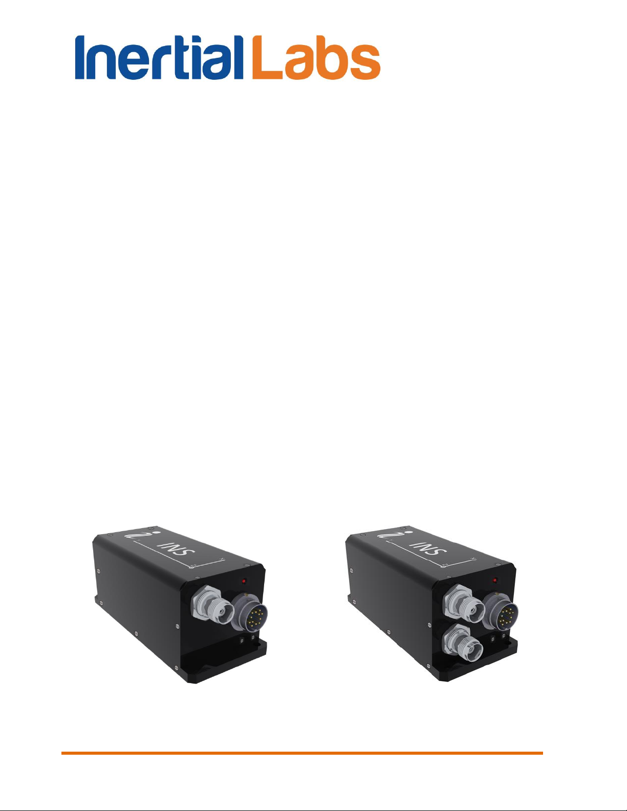
Fig. 1.1 Inertial LabsTM INS-B and INS-P
Fig. 1.2 Inertial LabsTM INS-D and INS-DL
INS
GUI User’s Manual
Table D.1 The Unit Status Word description .............................................................................. 236
1. Introduction
This manual is designed to study and use software for all modifications of
Inertial Labs™ Inertial Navigation System (INS) for its designed purposes.
Use of the INS should be restricted to only those who have read its user
manual and are following the safety measures specified in that user manual.
Inertial Labs
TM
provides the next models of INS products (see Fig. 1.1 to Fig.
1.4):
INS-B and INS-B-OEM (Basic model) – use high grade IMU and high
grade single antenna GNSS receiver;
INS-P and INS-P-OEM (Professional model) – use high-grade
Fluxgate magnetometers, high grade IMU and high grade single
antenna GNSS receiver;
INS-D, INS-DL and INS-D-OEM (Dual antenna model) – use high
grade IMU, dual-antenna GNSS receiver and measures static and
dynamic Heading, independent on magnetic field disturbance.
Notes:
1. In this document all information related to the INS-D is correct for the INS-DL,
unless otherwise specified.
2. In this document all information related to the INS-B, INS-P, INS-D are correct
for the INS-B-OEM, INS-P-OEM, INS-D-OEM respectively, unless otherwise
specified.
Inertial Labs, Inc
Tel: +1 (703) 880-4222, Fax: +1 (703) 935-8377 Website: www.inertiallabs.com
13
TM
Address: 39959 Catoctin Ridge Street, Paeonian Springs, VA 20129 U.S.A.
Page 14
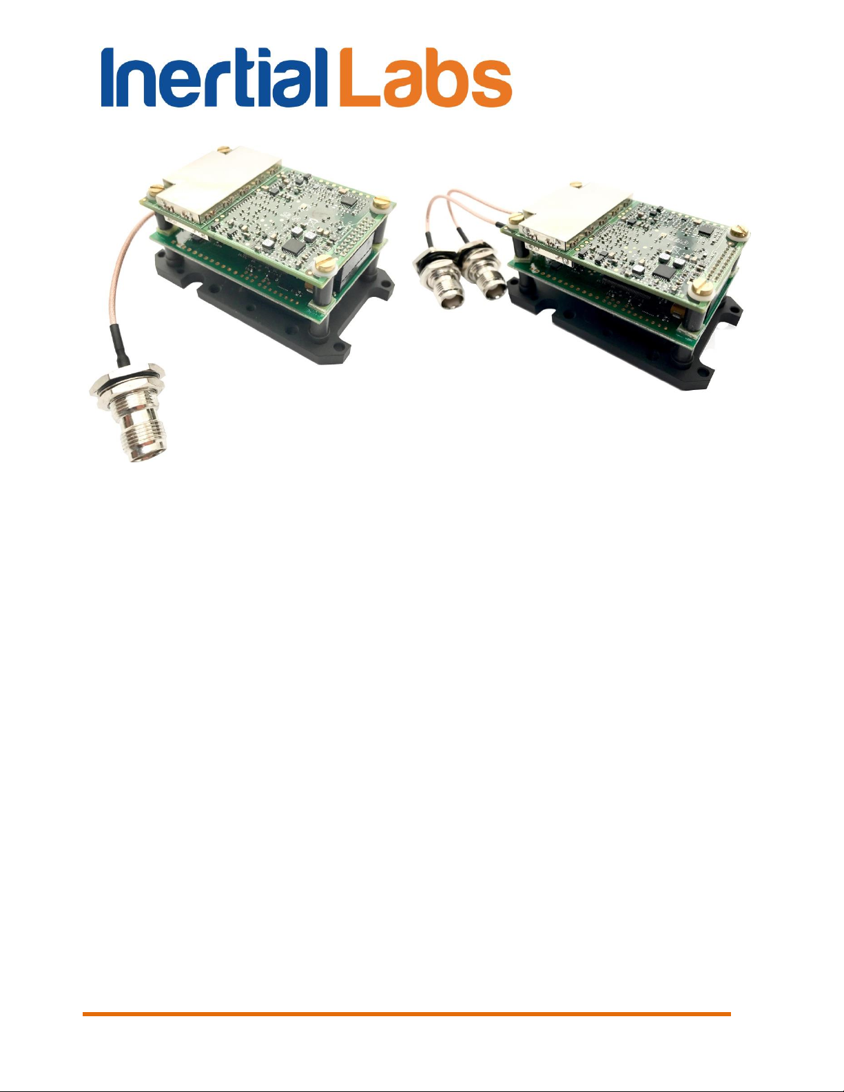
Fig. 1.3 Inertial LabsTM INS-B-OEM
and INS-P-OEM
Fig. 1.4 Inertial LabsTM INS-D-OEM and
INS-DL-OEM
INS
GUI User’s Manual
Inertial Labs, Inc
14
Tel: +1 (703) 880-4222, Fax: +1 (703) 935-8377 Website: www.inertiallabs.com
TM
Address: 39959 Catoctin Ridge Street, Paeonian Springs, VA 20129 U.S.A.
Page 15

The most important notes
Subject
Note
To view and
edit INS
parameters
INS must be connected to computer and powered.
Serial port number to which INS is connected and its baud
rate should be chosen in the “Test options” menu (see
section 4.1).
INS readiness
for operations
INS is ready to receive commands and to output data after
initialization time is completed (not more than 25 sec after
power on) so LED indicator switched color from yellow to
red.
At the first use
1. Please enter approximately true Latitude, Longitude,
Altitude and Date in the "Devices options", "IMU" tab (see
section 4.2.1). This allows correct INS start even at
absence of visible GNSS satellites.
2. Set correct value of the magnetic declination there. This
parameter is necessary to calculate true heading using
measured magnetic heading. Since INS firmware version
2.2.0.2 the magnetic declination can be calculated in the
INS continuously. Check “Auto” check-box in “Devices
options…” to activate this option.
After INS and
GNSS
antenna(s)
installation
Measure the GNSS antenna position relative to the IMU
(m). For INS-D measure also the secondary antenna
position relative to the IMU (m). Then enter these
coordinates in appropriate fields in “IMU” tab of the
“Device options” menu (see section 4.2.1).
Measurement
rate (update
rate)
It can be changed in the “Device options” menu, but it
must not exceed maximum value shown in the Table 4.1
(see section 4.2.8).
Object hard and
soft iron
compensation
Do not forget to calibrate INS-P on hard and soft iron after
mounting on the carrier object (see section 10.4). But if
“Use_mags” switch is disabled in the “Settings” tab of
“Correction options…” window, then such calibration is not
necessary.
Pressure
sensor
If the INS has no access to the ambient external pressure
(for example, if it is installed inside a pressurized cabin) or
if the INS pressure sensor can be exposed to speed air
INS
GUI User’s Manual
15
Inertial Labs, Inc
Tel: +1 (703) 880-4222, Fax: +1 (703) 935-8377 Website: www.inertiallabs.com
TM
Address: 39959 Catoctin Ridge Street, Paeonian Springs, VA 20129 U.S.A.
Page 16

streams, please set “Disabled” for the Baro-altimeter in the
"Pressure sensor" tab " of "Device options" menu to
switch the INS vertical correction to the GNSS altitude
only.
Automatic start
INS has ability to start operation automatically after power
on, with continuous output data in desirable output data
format (see section 10.6).
Changing
parameters of
GNSS receiver
or CAN, COM4
settings
After changing of parameters in “GNSS receiver” or “CAN
/ COM4” tab of the “Device options” menu it is necessary
to power off, power on the INS unit to restart onboard
GNSS receiver or to re-initialize COM4 port.
INS algorithm
adjustment
Features of INS algorithm and possibilities of their
adjustment are described in section “4.3. Correction
options”.
INS
GUI User’s Manual
16
Inertial Labs, Inc
Tel: +1 (703) 880-4222, Fax: +1 (703) 935-8377 Website: www.inertiallabs.com
TM
Address: 39959 Catoctin Ridge Street, Paeonian Springs, VA 20129 U.S.A.
Page 17

INS
GUI User’s Manual
1. General information
Operating system. This version of the GUI software is fully compatible with
the operating system MS Windows XP, MS Windows Vista, MS Windows 7.
Working with the software. The “Inertial Labs INS GUI” software is a
windows-based Win32 application, and standard means used in the
Windows (mouse and keyboard) are needed to use it. Directory structure
necessary for data storage is created by user. All necessary configurations
and calibration coefficients are stored in the INS nonvolatile memory, and
they are automatically loaded into the INS microprocessor. Calibration
coefficients are set by INS developers, and they can be changed, but only
under guidance of the INS developer. Upon termination the “Inertial Labs
INS GUI” software creates a default.prm file for its operation, in which the
latest used parameters of the microprocessor and shell are stored. During
work with the INS, the files with extensions .txt, .rtf, .prm, .dat and .bin can
be created. Files with extensions .txt and .rtf can be created by operator,
and files with extensions .prm, .dat and .bin are created automatically by the
software when it is saving text or graphical data.
Requirements to the system resources. The software requires 6 Mbytes of
RAM for proper operation. Hard disk capacity required for proper operation
is determined by the size of the GUI software files (approximately 12
MBytes) and by the files saved during operation, no more than 100 Mbytes.
Recommended screen resolution is 1280х1024 pixels. The INS is connected
to a computer through a standard COM port. The INS can also be connected
to a PC through a USB port with a COM-to-USB converter. In this case,
reliability of signal reception/transmission between a PC and the INS can
greatly depend on the quality of the COM-to-USB converter and on correct
configuration of its driver. INS manufacturer guarantees reliable operation of
the INS if it is connected directly to the COM port. In the Appendix A,
installation and configuration of drivers for one of the possible COM-to-USB
converters is described.
Requirements to operators. The INS GUI software uses a standard Windows
operating system. Therefore, operators should know the basic principles of
PC operation to use the GUI software, and they should be able to use the
MS Windows operating system.
Inertial Labs, Inc
Tel: +1 (703) 880-4222, Fax: +1 (703) 935-8377 Website: www.inertiallabs.com
TM
Address: 39959 Catoctin Ridge Street, Paeonian Springs, VA 20129 U.S.A.
17
Page 18
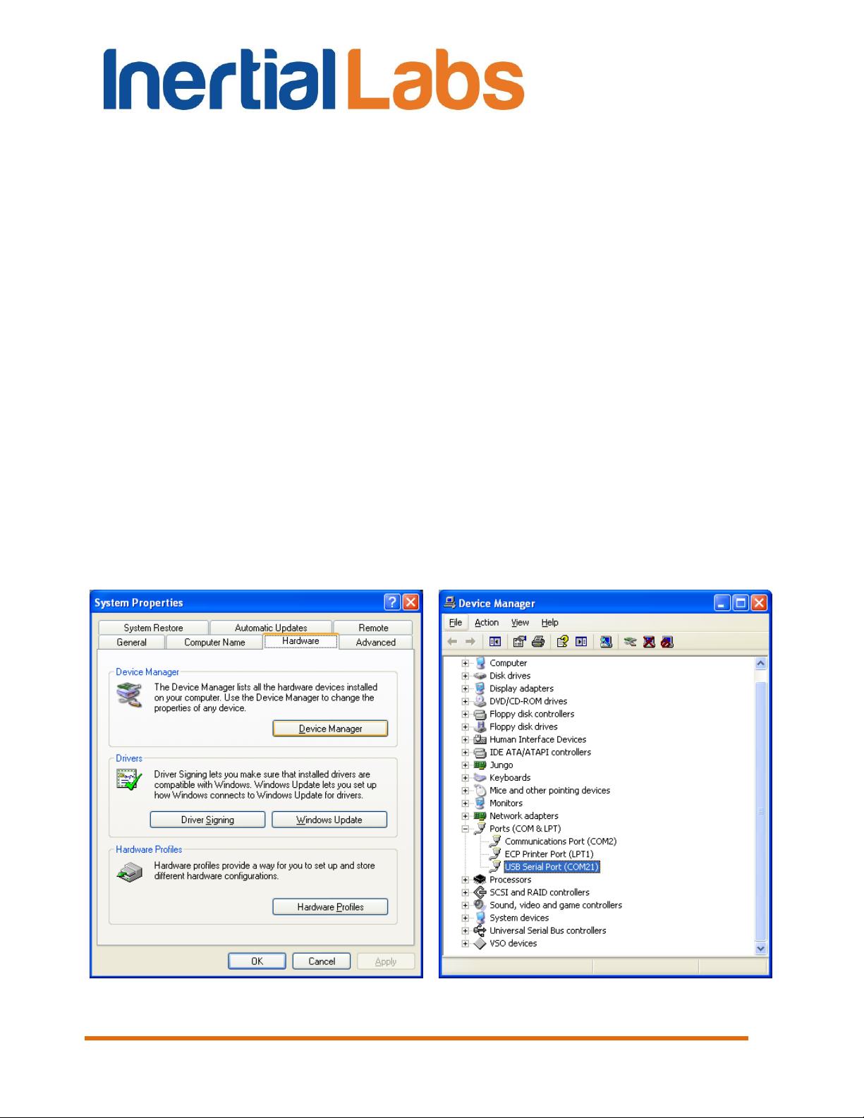
Fig. 2.1
Fig. 2.2
INS
GUI User’s Manual
2. Installation of drivers and configuration of PC parameters
The “Inertial Labs INS GUI” software doesn’t require any installation. Just
copy the software folder INS_GUI_002 to the working directory.
When you connect the INS to a standard computer COM port, drivers are
not needed. If the INS is connected to a USB port with a COM-to-USB
converter see “Appendix A. Installation of the COM-to-USB converter drivers
and configuration of PC parameters” for more details.
If you use the INS with RS-422 interface you need to install RS422-to-USB
converter driver. See “Appendix B. Installation of the MOXA Serial-to-USB
converter drivers (for INS with RS-422 interface)”
To know the numbers of the PC COM ports click “Device Manager” in the
“Hardware” tab of the “System Properties” window (Fig. 2.1). In the opened
“Device Manager” window (Fig. 2.2) you will see the COM ports which will
be marked as “Communications Port (COMN)” or “USB Serial Port
(COMN)” or “MOXA USB Serial Port (COMN)”. Number N in the port name
is assigned by OS.
Inertial Labs, Inc
Tel: +1 (703) 880-4222, Fax: +1 (703) 935-8377 Website: www.inertiallabs.com
18
TM
Address: 39959 Catoctin Ridge Street, Paeonian Springs, VA 20129 U.S.A.
Page 19
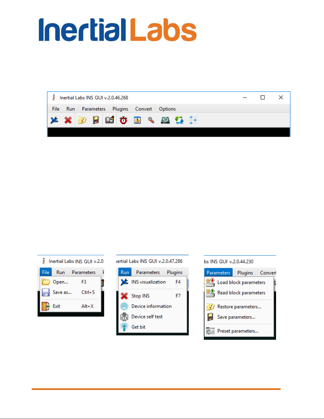
Fig. 3.1
Fig. 3.2
Fig. 3.3
Fig. 3.4
INS
GUI User’s Manual
3. Main menu of the program
The main menu of the “Inertial Labs INS GUI” software contains the
following items (see Fig. 3.1).
File Menu contains standard Windows file management commands (Fig.
3.2).
Run Menu contains the INS control commands (Fig. 3.3).
Parameters Menu contains operations with INS parameters (Fig. 3.4).
Plugins Menu contains the INS GUI plugins (Fig. 3.5).
Convert Menu contains conversion of binary data to the text format (Fig.
3.6).
Options Menu contains the INS configuration commands (Fig. 3.7).
TM
Inertial Labs, Inc
Tel: +1 (703) 880-4222, Fax: +1 (703) 935-8377 Website: www.inertiallabs.com
19
Address: 39959 Catoctin Ridge Street, Paeonian Springs, VA 20129 U.S.A.
Page 20
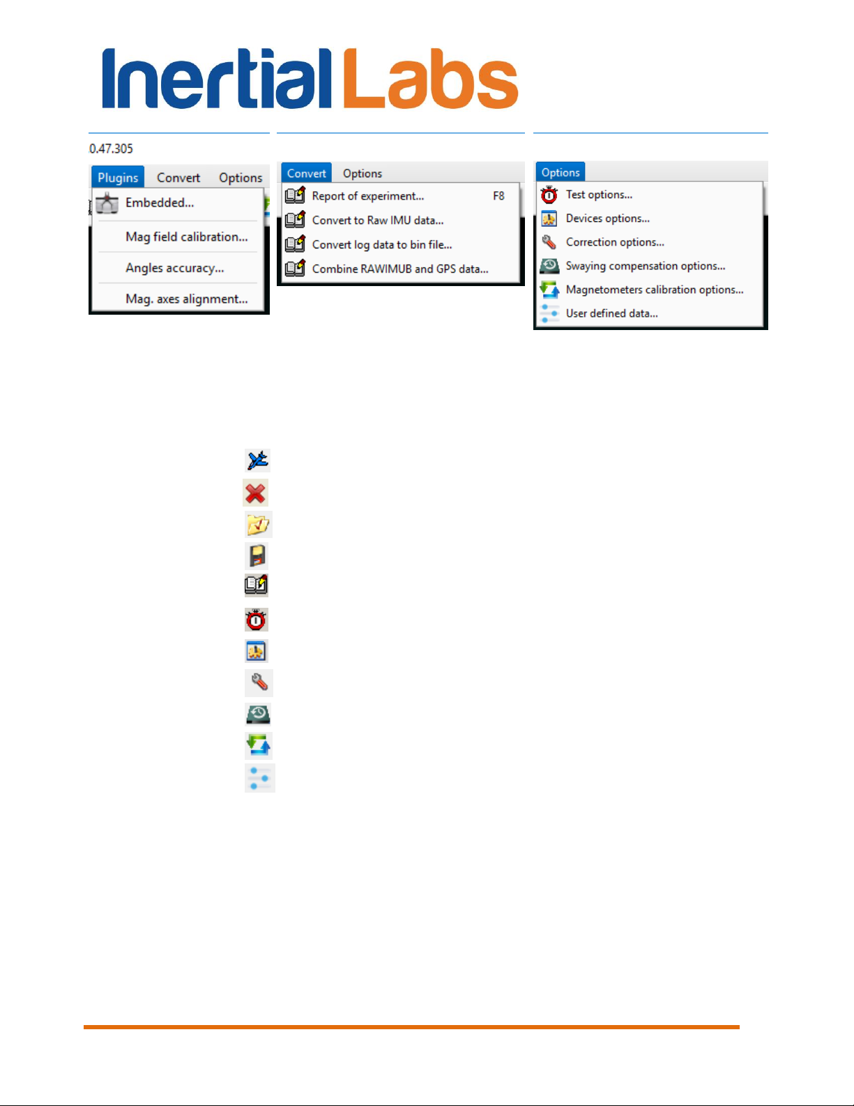
Fig. 3.5
Fig. 3.6
Fig. 3.7
Run:
- INS visualization, F4;
- Stop INS;
Parameters:
- Restore parameters;
- Save parameters;
Convert:
- Report of experiment, F8;
Options:
- Test options...;
- Device options...;
- Correction options…;
- Swaying compensation options;
- Magnetometers calibration options;
- User defined data.
GUI User’s Manual
Icons for the most often used commands are placed on toolbars.
INS
Inertial Labs, Inc
20
Tel: +1 (703) 880-4222, Fax: +1 (703) 935-8377 Website: www.inertiallabs.com
TM
Address: 39959 Catoctin Ridge Street, Paeonian Springs, VA 20129 U.S.A.
Page 21
INS
GUI User’s Manual
4. Options Menu
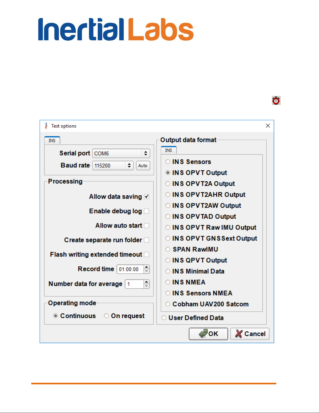
4.1. Test options
To set operation parameters of the INS, COM port, format of output data,
select “Test options…” (Fig. 3.7) from the “Options” menu (or click
button). A “Test Options” dialog box (Fig. 4.1) will be opened.
Fig. 4.1
You can set the following parameters in the “Test Options” window:
Inertial Labs, Inc
Tel: +1 (703) 880-4222, Fax: +1 (703) 935-8377 Website: www.inertiallabs.com
TM
Address: 39959 Catoctin Ridge Street, Paeonian Springs, VA 20129 U.S.A.
21
Page 22

INS
GUI User’s Manual
Serial port – number of the COM port to which main port of the INS
is connected.
Baud rate – is the set rate of computer COM port for connection of
INS unit. See section 4.2.7 for details. The default value of the baud rate is
115200 bps.
Allow data saving checkbox – allows to record the test data to file. If
it is unchecked then no file will be created and no message “Data are writing
in file” will be displayed.
Enable debug log – allows to record the log file of test run. In case
of the INS GUI crash it can be used to debug errors. Log file contains
information about commands that were sent by the INS GUI and appeared
errors. In case of errors this file should be sent to the Inertial Labs with brief
description of user actions.
Allow auto start checkbox – allows operation with INS which was
already started before run of the INS GUI software. See section 10.6 for
details.
Create separate run folder – allows automatic creation of separate
data folder for each run. On default this option is disabled.
Record time – sets data recording time in hours:minutes:seconds
format. The parameter is active when data is being saved to file. Values of
hours, minutes, seconds can be changed with the arrows or by entering the
required value from a keyboard.
Number data for average – the quantity of averaged data. This can
be used for smoothing of viewed data. Note that averaging relates to the
data output on the screen only and is not applied to the data written in a file.
The minimal value for the parameter is 1 and changed with the arrows to 1
or by entering the required value from a keyboard. The default value is 1.
Operating Mode – defines INS’s output method, Continuous or
stepped On Request. The default value is Continuous.
Output Data Format – sets format of the INS output data. Select
one of the formats:
“INS Sensors” (contains data from the devices inside INS – IMU (as
AHRS), GNSS receiver, pressure sensor),
Inertial Labs, Inc
Tel: +1 (703) 880-4222, Fax: +1 (703) 935-8377 Website: www.inertiallabs.com
TM
Address: 39959 Catoctin Ridge Street, Paeonian Springs, VA 20129 U.S.A.
22
Page 23

INS
GUI User’s Manual
“INS OPVT Output” (Orientation, Position, Velocity, Time),
“INS OPVT2A” (Orientation, Position, Velocity, Time, Dual-antenna
receiver data),
“INS OPVT2AW” (Orientation, Position, Velocity, Time, Dual-antenna
receiver data, GPS week),
“INS OPVT2AHR” (Orientation, Position, Velocity, Time, Dual-
antenna receiver data, with high resolution),
“INS OPVTAD” (Orientation, Position, Velocity, Time, external Aiding
Data),
“INS QPVT Output” (Quaternion of orientation, Position, Velocity,
Time),
“INS Minimal Data” (minimal configuration of orientation, position,
velocity and time data),
“INS OPVT & Raw IMU Data” (Orientation, Position, Velocity, Time
and raw IMU data);
SPAN rawimu (raw IMU data in NovAtel SPAN rawimub format);
“INS OPVT GNSSext” (Orientation, Position, Velocity and extended
information about time and the GNSS data,
“INS NMEA”,
“INS Sensors NMEA”,
“Cobham UAV 200 Satcom”
“User Defined Data” (see section 4.6 for details).
For more information on the output data format see Appendix C. The default
variant is “INS OPVT Output” data format.
Inertial Labs, Inc
Tel: +1 (703) 880-4222, Fax: +1 (703) 935-8377 Website: www.inertiallabs.com
TM
Address: 39959 Catoctin Ridge Street, Paeonian Springs, VA 20129 U.S.A.
23
Page 24
INS
GUI User’s Manual
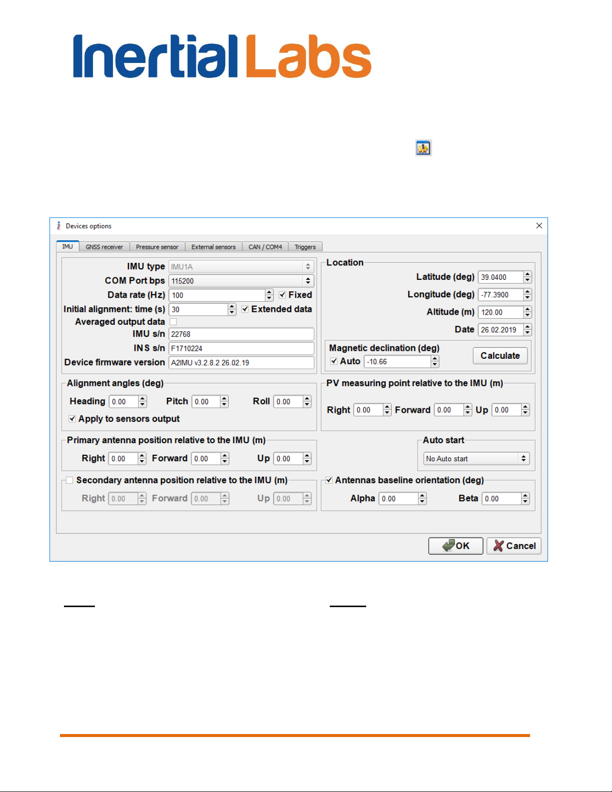
4.2. Devices options
To set and control of INS operation parameters, select “Devices
options…” from the “Options” menu (Fig. 3.7), or click button (Fig. 3.1).
A “Devices Options” (Fig. 4.2) dialog box will be opened. There are six
tabs “IMU”, “GNSS receiver”, “Pressure sensor”, “External sensors”, “CAN /
COM4”, “Triggers”.
Fig. 4.2
Note: “Device option…” item is available only if:
INS is powered,
and INS is connected to computer,
and СОМ port number and its baud rate are chosen properly,
and INS initialization time (about 25 sec after power on) is completed
so LED indicator lights red.
Inertial Labs, Inc
Tel: +1 (703) 880-4222, Fax: +1 (703) 935-8377 Website: www.inertiallabs.com
TM
Address: 39959 Catoctin Ridge Street, Paeonian Springs, VA 20129 U.S.A.
24
Page 25
INS
GUI User’s Manual
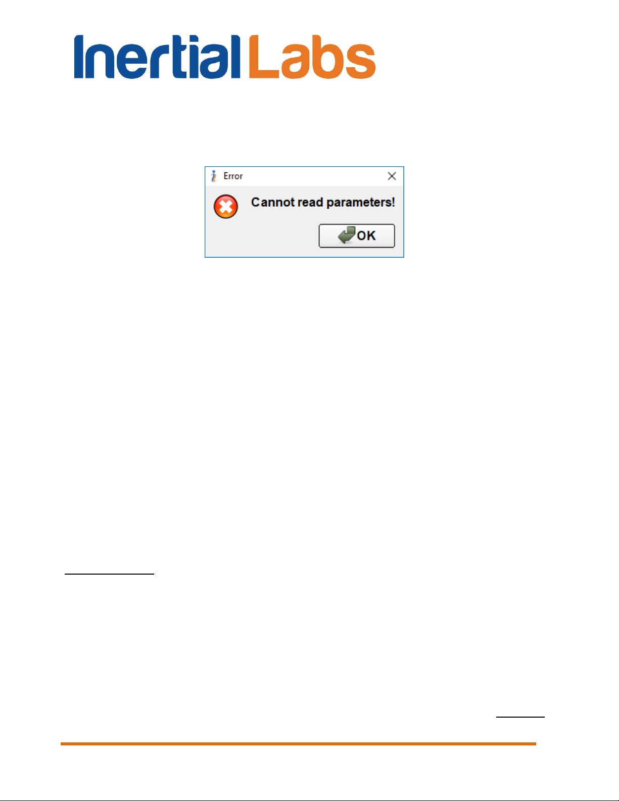
In the other case the error window with message “Cannot read
parameters!” appears over above window (see Fig. 4.3). Click “OK”, then
close “Device Options” window and choose the correct COM port number
(see section 4.1. Test options).
Fig. 4.3
4.2.1. “IMU” tab of “Devices options…” window
There are options for the Inertial Measurement Unit (IMU). You can check or
set the following parameters in the “IMU” tab of the “Devices Options”
window Fig. 4.2:
IMU type – shows type of IMU inside the INS unit. This parameter
cannot be changed.
COM Port bps – sets baud rate of the main INS COM port (see
section “4.2.7. Change of the main COM port baud rate” for details). Default
value is set to 115200 bps.
Data rate (Hz) – sets output data rate in Hertz. Minimal value of the
parameter is 1, maximal value is 200; it is changed with the arrows to 10 or
by entering the required value from a keyboard. Default value is set to 100.
Important note: the maximum data rate is limited by chosen baud rate of the COM port
which the INS unit is connected to, and also it depends on chosen output data format
(see Fig. 4.1) because of different number of transferred bytes. See section “4.2.8.
Limitation of the INS maximum output data rate” for details.
Fixed checkbox limits data rates to be factors of 200 Hz: (1, 2, 4, 5,
8, 10, 20, 25, 40, 50, 100, 200) Hz.
Initial alignment time (sec) – sets the initial alignment time in
seconds. The INS output data will be displayed in respective windows only
after the time set in this parameter is over. During initial alignment the INS
Inertial Labs, Inc
Tel: +1 (703) 880-4222, Fax: +1 (703) 935-8377 Website: www.inertiallabs.com
TM
Address: 39959 Catoctin Ridge Street, Paeonian Springs, VA 20129 U.S.A.
25
Page 26

INS
GUI User’s Manual
must be absolutely unmovable relative to the Earth. Minimum value of the
parameter is 1 and it can be changed to 1 with arrows or by entering the
necessary value from a keyboard. Default value is set to 30 seconds.
Extended data checkbox specifies format of block of the initial
alignment. If this checkbox is set then INS outputs extended initial alignment
block after initial alignment is completed. Otherwise INS outputs short block
of the initial alignment data (see Appendix C.1 for details).
Averaged output data checkbox – if it is checked then averaged
data are output at rate less than 200Hz. Otherwise instant data are output.
IMU s/n – specifies the serial number of the IMU inside the INS unit.
This parameter cannot be changed.
INS s/n – specifies the serial number of the INS in use. This
parameter cannot be changed.
Device firmware version – the firmware version of the INS in use. It
consists of symbols of the firmware type, firmware version and date of this
version issue separated by blanks. This parameter cannot be changed.
Latitude (deg) – initial latitude of the INS operating location.
Longitude (deg) – initial longitude of the INS operational location.
Altitude (m) – initial altitude above sea level of the INS operational
location.
Date – day, month and year when the INS is used.
Notes:
1. It is highly recommended to set current latitude, longitude and altitude for setting the
initial position in case of the GNSS data may be not available at the INS start.
2. It is necessary to set current latitude, longitude, altitude and date before hard/soft iron
calibration of the INS magnetometers (see section 8.2).
Magnetic declination (deg) – sets magnetic declination at the place
where the INS operates. The parameter value is changed by entering the
required value from a keyboard or by automatic calculation by click on
“Calculate” button, using Latitude, Longitude, Altitude and Date values.
Default value of the magnetic declination is set to 0.
Inertial Labs, Inc
Tel: +1 (703) 880-4222, Fax: +1 (703) 935-8377 Website: www.inertiallabs.com
TM
Address: 39959 Catoctin Ridge Street, Paeonian Springs, VA 20129 U.S.A.
26
Page 27

INS
GUI User’s Manual
Notes:
1. It is important to set the magnetic declination correctly for the INS operation because it
requires to know the true heading which is calculated by addition of the magnetic
declination to measured magnetic heading.
2. Magnetic declination is calculated using the World Magnetic Model produced by the
U.S. National Geophysical Data Center and the British Geological Survey, see
http://www.ngdc.noaa.gov/geomag/WMM/DoDWMM.shtml
Since INS firmware version 2.2.0.2 the magnetic declination can be
calculated in the INS continuously using calculated current position and
time. Check “Auto” check-box (see Fig. 4.2) to activate this option.
Alignment angles (deg) – angles between the INS axes and the
carrier object are set after INS mounting, see “Appendix E. Variants of the
Inertial Labs™ INS mounting relative to object axes”. Default values are set
to 0 degrees.
PV measuring point relative to the IMU (m) – sets coordinates of
measuring point for Position and Velocity calculation. Set coordinates of the
measuring point relative to the accelerometer mass-center of the INS unit
(see Appendix F, Fig. F.1) in the object axes – on the right, forward and up
directions, in meters.
Auto start – enables or disables automatic start of the INS and data
output after power on without any command from the host computer. See
section 10.6 for details.
Primary antenna position relative to the IMU (m) – sets the
primary GNSS antenna mounting lever relative to the INS unit, in meters.
After the INS unit and GNSS antenna installation on the carrier object it is
necessary to measure the center of antenna position relative to the
accelerometer mass-center of the INS unit, in the object axes – on the right,
forward and up directions (see Appendix F). Then it is necessary to enter
these coordinates in appropriate fields in the IMU tab (Fig. 4.2) and click
“OK” to apply these coordinates and store them in the INS nonvolatile
memory.
Secondary antenna position relative to the IMU (m) – sets the
secondary GNSS antenna mounting lever relative to the INS unit, in meters.
This option is supported for INS-D with firmware version since 2.9.1.7 and
allows the secondary antenna installation in arbitrary (but known) position
relative to the INS-D unit and primary antenna.
Inertial Labs, Inc
Tel: +1 (703) 880-4222, Fax: +1 (703) 935-8377 Website: www.inertiallabs.com
TM
Address: 39959 Catoctin Ridge Street, Paeonian Springs, VA 20129 U.S.A.
27
Page 28

INS
GUI User’s Manual
Note: Earlier two antennas should be installed in parallel to the longitudinal axis of the
carrier object.
The secondary antenna position can be set in two ways. One way is to
measure the center of antenna position in meters relative to the
accelerometer mass-center of the INS unit, in the object axes – on the right,
forward and up directions (see Appendix F), and then enter these
coordinates in the “Secondary antenna position relative to the IMU (m)”
fields (see Fig. 4.2). Click “OK” to apply these coordinates and store them in
the INS nonvolatile memory.
Antennas baseline orientation (deg) – provides alternate way to
set the secondary antenna position – as orientation of the baseline between
two antennas relative to the carrier object axes (see Appendix F for details).
There two angles Alpha, Beta should be measured and entered in
appropriate fields in “Antennas baseline orientation (deg)” (see Fig. 4.2).
Then click “OK” to apply these angles and store them in the INS nonvolatile
memory. This setting is supported for INS-D with firmware version since
2.9.1.7.
Notes:
1. If after the INS mounting its axes X, Y, Z are parallel to the carrier object lateral,
longitudinal and vertical axes, then the antenna coordinates should be measured in the
directions of the INS X, Y and Z axes.
2. On the other hand, the INS unit can be mounted on the object in any known position
(up to upside-down, upright etc., see Appendix E. Variants of the Inertial LabsTM INS
mounting relative to the object axes). In that case please set the GNSS antenna
coordinates measured just in the object axes (on the right, forward and up directions), but
not in the INS axes.
Inertial Labs, Inc
Tel: +1 (703) 880-4222, Fax: +1 (703) 935-8377 Website: www.inertiallabs.com
TM
Address: 39959 Catoctin Ridge Street, Paeonian Springs, VA 20129 U.S.A.
28
Page 29
INS
GUI User’s Manual
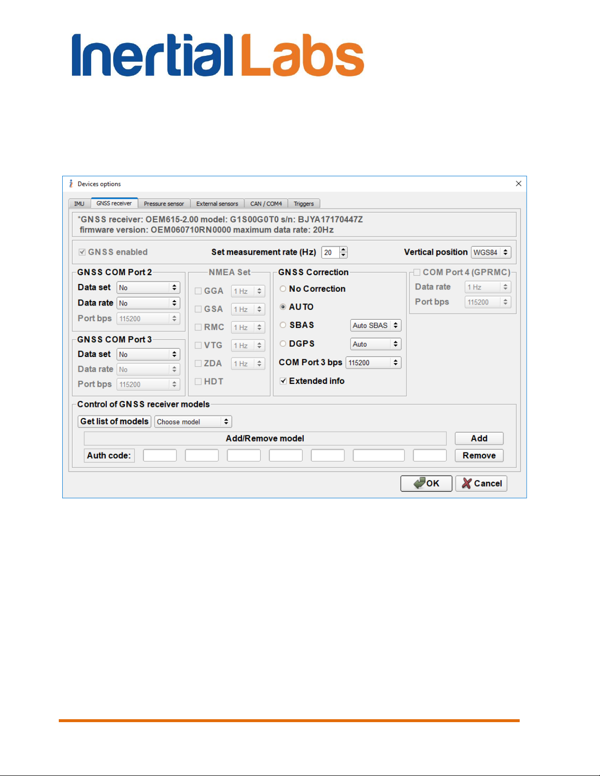
4.2.2. “GNSS receiver” tab of “Devices options…” window
There are options for the onboard GNSS receiver (see Fig. 4.4). The first
two rows show the next information: GNSS receiver name, model, serial
number, firmware version and maximum data rate.
Fig. 4.4
There are the next very important settings for the GNSS receiver:
GNSS enabled – enables using of the GNSS data. This parameter
cannot be changed.
Set measurement rate (Hz) – rate of the GNSS data update. It is
highly recommended to set this rate to the maximum value supported by
actual model of the GNSS receiver. Note the INS unit controls entered rate
of the GNSS data and does not allow to set it larger than supported by the
current GNSS receiver model.
Inertial Labs, Inc
Tel: +1 (703) 880-4222, Fax: +1 (703) 935-8377 Website: www.inertiallabs.com
TM
Address: 39959 Catoctin Ridge Street, Paeonian Springs, VA 20129 U.S.A.
29
Page 30
GUI User’s Manual
Vertical position – allows to choose variant of output altitude –
above mean sea level MSL) or above WGS84 ellipsoid.
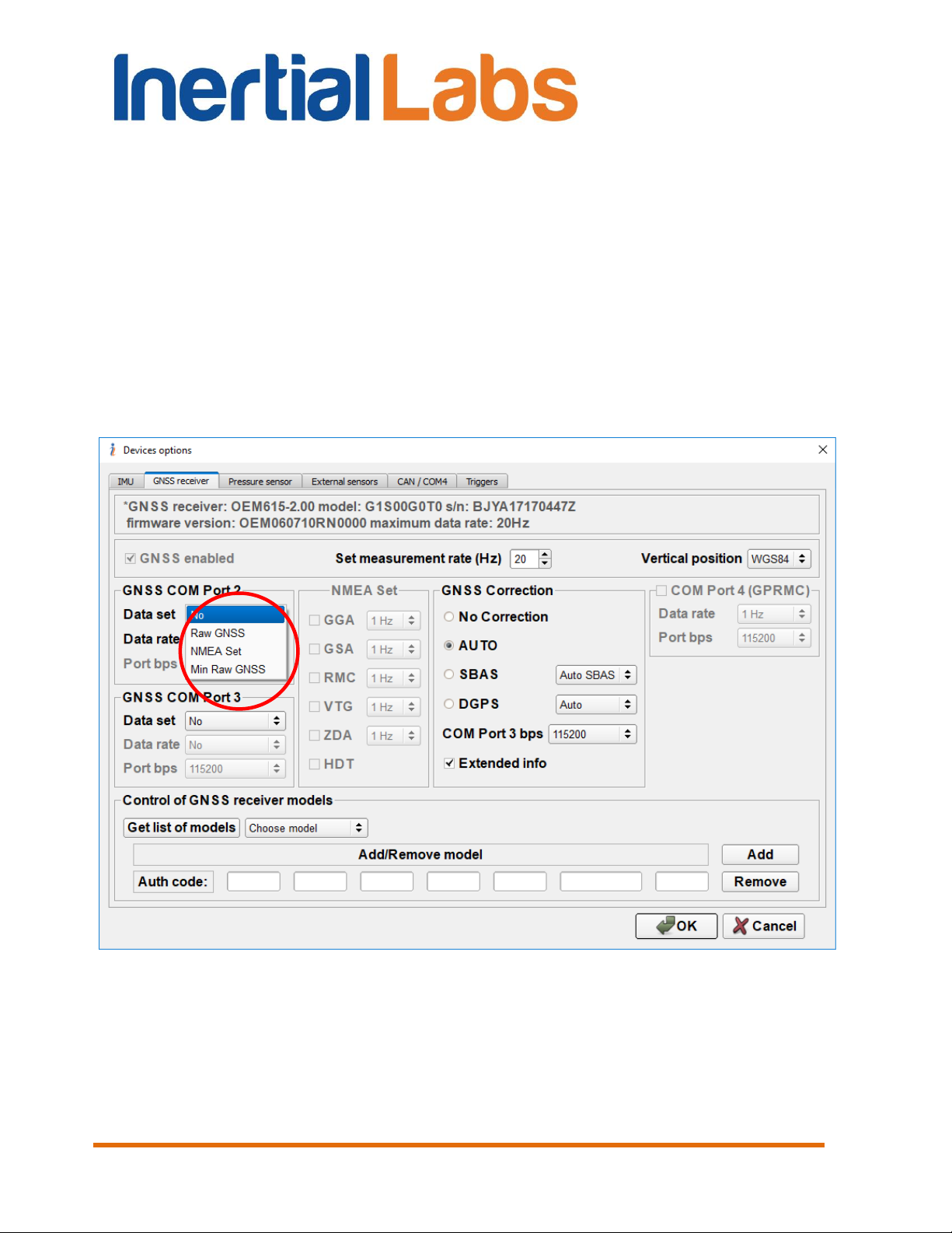
GNSS COM Port 2 fields configure COM2 port setting for output
GNSS raw data or NMEA data set:
– Data set – allows choosing desirable set of GNSS receiver data for
output through COM2 port. User can choose GNSS raw data (full or
minimal set) or NMEA set output in the drop-down list (see Fig. 4.5).
When “No” is chosen then no GNSS data are output. Default setting
is “No”.
INS
Fig. 4.5
– Data rate – sets frequency of COM2 port raw GNSS data output.
When Data set is set to “Raw GNSS” or “Min Raw GNSS” user can
choose frequency of data output in the drop-down list (see Fig. 4.6).
See section “12.1. Recording of raw GNSS data” for more details.
Inertial Labs, Inc
Tel: +1 (703) 880-4222, Fax: +1 (703) 935-8377 Website: www.inertiallabs.com
TM
Address: 39959 Catoctin Ridge Street, Paeonian Springs, VA 20129 U.S.A.
30
Page 31

INS
GUI User’s Manual
Fig. 4.6
– Port bps – allows setting baud rate of the COM2 port for output
GNSS data. User can choose needed COM2 port baud rate in the
drop-down list (see Fig. 4.7). Default value is “115200”. If GNSS raw
data are chosen for COM port 2 output, then it is necessary to set the
same COM Port baud rate in the GNSS_Reader program for raw
GPS data recording (see section “12.1. Recording of raw GNSS data”
for more details).
Note: The standard COM-port baud rate 115200 bps can provide GPS L1 raw data
frequency up to 5 Hz. Raw data with higher frequency, using GPS + GLONASS, L1/L2
frequencies may contain gaps, so it is necessary to use USB port on host computer and
to increase COM Port baud rate. Set 921600 bps baud rate to provide maximum 20 Hz
GNSS raw data output. Please contact the Inertial Labs about details.
Inertial Labs, Inc
Tel: +1 (703) 880-4222, Fax: +1 (703) 935-8377 Website: www.inertiallabs.com
TM
Address: 39959 Catoctin Ridge Street, Paeonian Springs, VA 20129 U.S.A.
31
Page 32

INS
GUI User’s Manual
Fig. 4.7
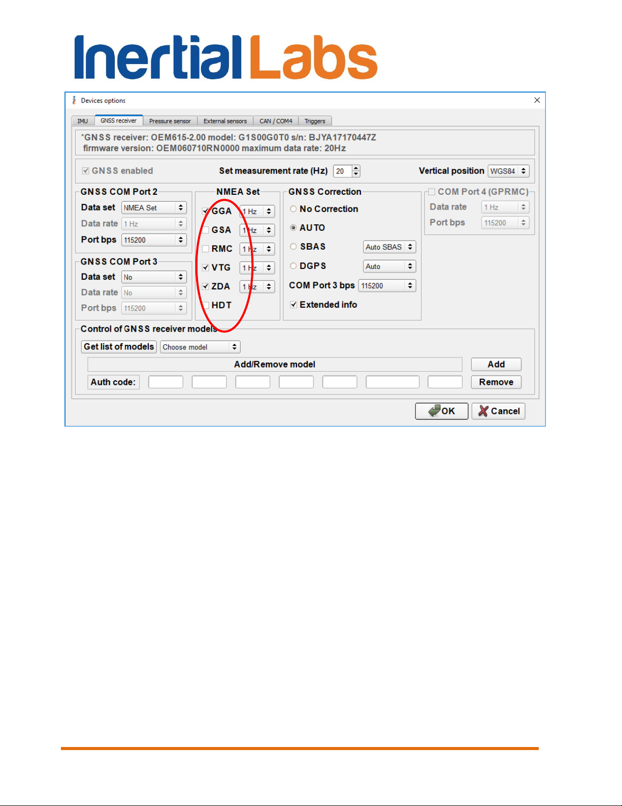
– NMEA Set – allows setting desired NMEA messages for output
through COM2 port when NMEA Set is chosen in Data Set (see Fig.
4.8). By default INS outputs GPGGA, GPVTG and GPZDA if no
checkboxes in NMEA Set are chosen.
It is possible to set desirable frequency for each chosen NMEA
message. User can choose frequency of data output in drop-down list
next to the NMEA message name (see Fig. 4.9).
Inertial Labs, Inc
Tel: +1 (703) 880-4222, Fax: +1 (703) 935-8377 Website: www.inertiallabs.com
TM
Address: 39959 Catoctin Ridge Street, Paeonian Springs, VA 20129 U.S.A.
32
Page 33
INS
GUI User’s Manual
Fig. 4.8
Inertial Labs, Inc
Tel: +1 (703) 880-4222, Fax: +1 (703) 935-8377 Website: www.inertiallabs.com
TM
Address: 39959 Catoctin Ridge Street, Paeonian Springs, VA 20129 U.S.A.
33
Page 34

INS
GUI User’s Manual
Fig. 4.9
GNSS COM Port 3 fields configure COM3 port setting for output
GNSS raw data or GPRMC messages (they are used only for INS data
synchronization with LiDAR):
– Data set – allows choosing desirable set of GNSS receiver data for
output through COM3 port. User can choose GNSS raw data (full or
minimal set) or GPRMC message in the drop-down list (see Fig.
4.10). When “No” is chosen then no GNSS data are output. Default
setting is “No”.
– Data rate – sets frequency of COM3 port data output. When Data
set is set other than “No”, user can choose frequency of data output
in the drop-down list (see Fig. 4.11).
– Port bps – allows setting baud rate of the COM3 port. User can
choose needed COM3 port baud rate in the drop-down list: 9600,
19200, 38400, 57600, 115200, 230400, 460800 bps. Default value is
115200 bps.
Inertial Labs, Inc
Tel: +1 (703) 880-4222, Fax: +1 (703) 935-8377 Website: www.inertiallabs.com
TM
Address: 39959 Catoctin Ridge Street, Paeonian Springs, VA 20129 U.S.A.
34
Page 35

INS
GUI User’s Manual
Fig. 4.10
GNSS Correction fields adjust correction of GNSS receiver data to
improve position accuracy. Type of GNSS correction is chosen by radio
button (see Fig. 4.4). Default value is “AUTO”. See section “10.2.1. GNSS
correction” for details.
Note: COM3 port can be used for input of the GNSS corrections only if Data Set
parameter in the GNSS COM Port 3 field is set to “No”.
Control of GNSS receiver models field allows adding, changing,
and removing of GNSS receiver model (see Fig. 4.4). For details see section
10.2.2 “Control of GNSS receiver model”.
Inertial Labs, Inc
Tel: +1 (703) 880-4222, Fax: +1 (703) 935-8377 Website: www.inertiallabs.com
TM
Address: 39959 Catoctin Ridge Street, Paeonian Springs, VA 20129 U.S.A.
35
Page 36

INS
GUI User’s Manual
Fig. 4.11
Extended info checkbox – allows extended information about GNSS
data. Uncheck this checkbox to provide compatibility of new INS GUI with
INS units that have older firmware than 2.2.1.0. Default setting is enabled
extended info.
COM Port 4 (GPRMC) fields configure COM4 port setting for output
of GPRMC messages
– Data rate – sets frequency of COM4 port data output.
– Port bps – sets baud rate of the COM4 port. User can choose
needed COM3 port baud rate in the drop-down list: 9600, 19200,
38400, 57600, 115200, 230400, 460800 bps. Default value is 115200
bps.
Notes:
1. Not all Inertial LabsTM INS units have four COM ports. Please contact Inertial Labs
about INS configuration.
Inertial Labs, Inc
Tel: +1 (703) 880-4222, Fax: +1 (703) 935-8377 Website: www.inertiallabs.com
TM
Address: 39959 Catoctin Ridge Street, Paeonian Springs, VA 20129 U.S.A.
36
Page 37

INS
GUI User’s Manual
2. Since INS GUI version 2.0.46.279 from 2018-07-26 the COM4 port configuration is
transferred to “CAN / COM4” tab of “Devices options…” window (see section 4.2.5) to
combine settings of all variants of COM4 port using.
Important note: after applying of any changes in the “GNSS receiver” tab by clicking
“OK” button, it is necessary to switch off, switch on INS unit to restart onboard GNSS
receiver.
4.2.3. “Pressure sensor” tab of “Devices options…” window
In this tab it is possible to choose the pressure sensor that is used for the
INS altitude correction (see Fig. 4.12).
Fig. 4.12
Baro-altimeter drop-down list contains variants of the pressure
sensor using for INS altitude correction:
- disabled;
- primary altitude sensor;
- secondary altitude sensor.
Inertial Labs, Inc
Tel: +1 (703) 880-4222, Fax: +1 (703) 935-8377 Website: www.inertiallabs.com
TM
Address: 39959 Catoctin Ridge Street, Paeonian Springs, VA 20129 U.S.A.
37
Page 38

INS
GUI User’s Manual
On default Baro-altimeter is disabled.
Pressure sensor noise STD sets value of standard deviation of the
pressure sensor noise.
See section “10.3. Features of Altitude calculation in the INS” for more
detailed explanation of operations with the pressure sensor.
4.2.4. “External sensors” tab of “Devices options…” window
Using external sensors data can greatly improve INS position, velocity and
orientation calculation during long-time GNSS outage. INS GUI allows to
configure INS operation with different types of the external sensors.
Choice of available external sensors and setting of their parameters can be
done in the “External sensors” tab of “Devices options…” window (see Fig.
4.13).
Fig. 4.13
Inertial Labs, Inc
Tel: +1 (703) 880-4222, Fax: +1 (703) 935-8377 Website: www.inertiallabs.com
TM
Address: 39959 Catoctin Ridge Street, Paeonian Springs, VA 20129 U.S.A.
38
Page 39

INS
GUI User’s Manual
4.2.4.1. Parameters of encoder-based odometer
INS GUI supports INS operation with two types of odometers:
odometer with OBDII interface (converted to RS-232);
encoder-based odometer (wheel speed sensor) with pulse/bi-phase
signals.
Parameters of OBDII odometer connection to INS COM4 port can be set in
“CAN / COM4” tab of the “Devices options…” window (see section 4.2.5).
Note INS unit should be equipped to accept encoder-based odometer data.
Please contact Inertial Labs for information about this.
For using encoder-based odometer it is necessary to check “Encoder-
based odometer” checkbox (see Fig. 4.13) and configure the next
parameters:
– Pulse length is the distance in meters between low to high transitions of
the encoder signal;
– Odometer offset is the lever arm measured from the accelerometer
mass-center of the INS unit to the point at which the vehicle's tire makes
contact with the road in the vehicle co-ordinate frame, in the right,
forward and vertical directions.
– STD_Vh (m/s) is standard deviation of the odometer noise. Usually its
value is 0.10 m/s, but it depends on encoder.
– k_Sigma_V is residual threshold. Its default value is 10.
Please contact Inertial Labs to get recommendations for odometer
parameters value.
See section “10.7. INS operation with odometer” for more details.
4.2.4.2. Using the main COM1 port to receive external aiding data
The Inertial LabsTM INS uses the main COM1 port for commands and data
transfer between the Inertial LabsTM INS and the host computer.
Since INS firmware version 2.8.2.0 it is possible to send external aiding data
to INS unit using the main COM1 port during INS ordinary operation when
INS outputs data through COM1 port.
Inertial Labs, Inc
Tel: +1 (703) 880-4222, Fax: +1 (703) 935-8377 Website: www.inertiallabs.com
TM
Address: 39959 Catoctin Ridge Street, Paeonian Springs, VA 20129 U.S.A.
39
Page 40

INS
GUI User’s Manual
Check “COM1 Aiding data” checkbox (see Fig. 4.13) to allow aiding data
input. By default aiding data input is disabled.
Check/set the following parameters for Kalman Filter, in the next fields:
– “STD_fi_la (m)”, “STD_h (m)” – noise of external horizontal and vertical
position aiding data;
– “STD_Vh (m/s)”, “STD_Vv (m/s)” – noise of horizontal and vertical
speed data;
– “k_Sigma_V”, “k_Sigma_coord” – Kalman filter residuals thresholds.
Please contact Inertial Labs to get recommendations for above parameters
value.
See INS ICD, section “6.6.4. Aiding data input through the main COM port”
for details.
4.2.4.3. Using external magnetic compass
The Inertial LabsTM INS can be factory configured to use the external OS3DFG Stand Alone Magnetic Compass (SAMC) to measure components of the
Earth magnetic field. The SAMC could be installed in part of carrier object
with good magnetic environment.
Check “Use external magnetic compass” check-box (see Fig. 4.13) to use
the SAMC.
If INS unit contains on-board magnetometers then after check “Use external
magnetic compass” check-box the SAMC will be used instead of on-board
magnetometers.
Notes:
1. Before using of external OS3D-FG SAMC, it is necessary to align the SAMC axes to
INS axes (see section 10.9 for details).
2. If external OS3D-FG SAMC is used, then hard/soft iron calibration of its
magnetometers should be performed in the same way as for INS magnetometers (see
section 10.4 for details).
Inertial Labs, Inc
Tel: +1 (703) 880-4222, Fax: +1 (703) 935-8377 Website: www.inertiallabs.com
TM
Address: 39959 Catoctin Ridge Street, Paeonian Springs, VA 20129 U.S.A.
40
Page 41

INS
GUI User’s Manual
4.2.5. “CAN / COM4” tab of “Devices options…” window
“CAN / COM4” tab (see Fig. 4.14) combines configuration of CAN
messages output and variants of COM4 port using to do not allow
simultaneous choice of incompatible variants and other mismatch.
Fig. 4.14
4.2.5.1. Configuration of CAN messages output
To allow INS output of CAN messages it is necessary to choose variant of
the CAN data in the drop-down list (see Fig. 4.15). The Inertial LabsTM INS
supports CAN standards 2.0A and 2.0B – with 11 bit base identifier and 29
bit extended identifier.
Inertial Labs, Inc
Tel: +1 (703) 880-4222, Fax: +1 (703) 935-8377 Website: www.inertiallabs.com
TM
Address: 39959 Catoctin Ridge Street, Paeonian Springs, VA 20129 U.S.A.
41
Page 42

INS
GUI User’s Manual
Fig. 4.15
Then in the “CAN / COM4” tab the user can configure the following
parameters (see Fig. 4.14):
- CAN baud rate;
- Components of the CAN identifier – Priority_EDP_DP, PDU_Format,
Device identifier;
- CAN message set.
See section “10.8. Operations with CAN data” for details.
Notes:
1. It is necessary to power off / on the INS after changing any of parameters in “CAN /
COM4” tab to re-initialize CAN port.
2. INS GUI software checks compatibility of chosen options in the “CAN / COM4” tab. So
if “Use CAN output” is set, then COM4 cannot be used for GPRMC, IMU TGA output or
for operations with OBD_Link odometer.
4.2.5.2. Configuration of COM4 port
“COM Port 4” fields (see Fig. 4.14) allow to choose variant of COM4 port
using as Fig. 4.16 shows:
- Disabled;
- OBDII odometer – to use COM4 for connection of odometer with OBDII
interface (converted to RS-232);
- GPRMC output – to output NMEA GPRMC messages through COM4
port;
- IMU TGA output – to output high frequency IMU data (time, gyros,
accelerometers) through COM4 port.
Inertial Labs, Inc
Tel: +1 (703) 880-4222, Fax: +1 (703) 935-8377 Website: www.inertiallabs.com
TM
Address: 39959 Catoctin Ridge Street, Paeonian Springs, VA 20129 U.S.A.
42
Page 43

INS
GUI User’s Manual
Fig. 4.16
Also, user should configure the next parameters in the “COM Port 4” fields:
- Data rate – for data input / output through COM4 port;
- Port bps – COM4 port baud rate.
Notes:
1. It is necessary to power off / on the INS after changing any of parameters in the “COM
Port 4” field to re-initialize COM4 port.
2. INS GUI software checks compatibility of chosen options in the “CAN / COM4” tab. So
if other than “Disabled” variant is chosen in the “COM Port 4” fields, then CAN messages
cannot be output, and “Use CAN output” becomes “Disabled”.
4.2.5.3. Parameters of OBDII odometer
For using OBDII odometer it is necessary to choose appropriate variant in
the “COM Port 4” field (see Fig. 4.14, Fig. 4.16)
Then it is necessary to set the next parameters of COM4 port (see Fig.
4.14):
– Data rate that specifies the frequency of the odometer data input in
Hertz. Minimum value of the parameter is 1 Hz and it can be changed
with arrows or by entering the necessary value from a keyboard. The
default value is set to 5Hz.
– Port bps that sets the baud rate of COM4 which provides input of the
odometer data. User can choose needed COM4 port baud rate in the
drop-down list: 4800, 9600, 14400, 19200, 38400, 57600, 115200,
230400, and 460800 bps. Default value is 115200 bps.
Also, it is necessary to configure INS Kalman Filter parameters for odometer
in the “External sensors” tab of the “Devices options…” window (see Fig.
4.13):
Inertial Labs, Inc
Tel: +1 (703) 880-4222, Fax: +1 (703) 935-8377 Website: www.inertiallabs.com
TM
Address: 39959 Catoctin Ridge Street, Paeonian Springs, VA 20129 U.S.A.
43
Page 44

INS
GUI User’s Manual
– STD_Vh (m/s) is standard deviation of the odometer noise. Usually its
value is 0.28 m/s.
– k_Sigma_V is residual threshold. Its default value is 10.
See section “10.7. INS operation with odometer” for more details.
Important note: it is necessary to power off / on the INS after changing any of
parameters in the “COM Port 4” field to re-initialize COM4 port.
4.2.6. “Triggers” tab of “Devices options…” window
In the “Triggers” tab the user can set the following parameters (see Fig.
4.17):
Mark inputs control – allows adjusting processing of mark input
signal that can be used to trigger specific GNSS raw receiver data. See
section “13.2. Processing of mark input signal” for details.
PPS control fields adjust the pulse-per-second (PPS) signal
generated by GNSS receiver for data synchronization with other devices.
See section “13.1. Control of PPS output signal” for details.
Important note: after applying of any changes in the “Triggers” tab by clicking “OK”
button, it is necessary to switch off, switch on INS unit to restart onboard GNSS receiver.
Inertial Labs, Inc
Tel: +1 (703) 880-4222, Fax: +1 (703) 935-8377 Website: www.inertiallabs.com
TM
Address: 39959 Catoctin Ridge Street, Paeonian Springs, VA 20129 U.S.A.
44
Page 45

INS
GUI User’s Manual
Fig. 4.17
4.2.7. Change of the main COM port baud rate
The main COM port is used for the INS connection to the host computer for
receiving commands and output of INS data. The default baud rate for the
main COM port is set to 115200 bps (maximum for the standard COM-port).
If the host computer requires other baud rate for the INS connection, then
user can choose one from the next list: 4800, 9600, 14400, 19200, 38400,
57600, 115200, 230400, and 460800 bps. The same baud rate must be set
in the “Test Options” of the INS GUI.
Notes:
1. Baud rate change is implemented in the INS firmware version since 2.2.0.0 and it is
supported by INS GUI since version 2.0.19.78 from 03/18/2016.
2. To allow baud rate change the INS unit must be connected to computer and powered.
3. Standard COM-port of a host computer (PC) does not support baud rate greater than
115200 bps. Therefore some Serial-to-USB adapter should be used for INS connection
to the host computer.
Inertial Labs, Inc
Tel: +1 (703) 880-4222, Fax: +1 (703) 935-8377 Website: www.inertiallabs.com
TM
Address: 39959 Catoctin Ridge Street, Paeonian Springs, VA 20129 U.S.A.
45
Page 46

INS
GUI User’s Manual
4. Baud rate must be set the same both for INS unit and in the INS GUI to allow this
software to control INS unit.
At the first, set correct COM port baud rate in the “Test Options” (see Fig.
4.1). It must be the same as it set in the INS unit. If COM port baud rate in
the INS unit is unknown then click “Auto” button. After several seconds
window with caption “Serial port baud rate XXXXXX was successfully
determined” will appear (see Fig. 4.18) and determined baud rate will appear
in the “Test Options” window.
Fig. 4.18
Inertial Labs, Inc
Tel: +1 (703) 880-4222, Fax: +1 (703) 935-8377 Website: www.inertiallabs.com
TM
Address: 39959 Catoctin Ridge Street, Paeonian Springs, VA 20129 U.S.A.
46
Page 47

INS
GUI User’s Manual
To change COM port baud rate in the INS unit go to the “Devices Options”,
“IMU” tab (see Fig. 4.2) and choose necessary baud rate from the list as Fig.
4.19 shows.
After the baud rate choice click “OK” button to load changed parameters to
the INS nonvolatile memory. Then the information windows shown on the
Fig. 4.20 and Fig. 4.21 appear. Click “OK” button to close these windows.
Note COM port baud rate in the “Test Options” will change to chosen value,
too, to keep communication between the INS GUI software and INS unit.
Fig. 4.19
Inertial Labs, Inc
Tel: +1 (703) 880-4222, Fax: +1 (703) 935-8377 Website: www.inertiallabs.com
TM
Address: 39959 Catoctin Ridge Street, Paeonian Springs, VA 20129 U.S.A.
47
Page 48

Fig. 4.20
ngthpackage_le * ytebits_per_b
ateCOM_baud_r
atemax_meas_r
Fig. 4.21
INS
GUI User’s Manual
4.2.8. Limitation of the INS maximum output data rate
When setting of the measurement rate for the INS unit in the “Devices
Options”, “IMU” tab (see Fig. 4.2) it is essential to ensure the chosen baud
rate is capable of handling the data throughput with desirable data rate. The
maximum measurement rate (Hz) can be calculated using the baud rate and
data package length:
, (4.1)
where COM_baud_rate is COM port baud rate (bits/s); bits_per_byte = 11
bits per one transferred byte of data; package_length for binary data =
payload length plus 8 bytes of overhead. See Appendix C, Tables C.3, C.7
to C.11, C.13, C.19, C.20, C.25, C.26 for payload length of binary output
data formats. The package_length of the text output data formats
correspond to their structure shown in Appendix C.
Table 4.1 contains data package length for each output data format and also
maximum measurement rate calculated by formula (4.1) with some spare.
Note the maximum measurement rate of INS data is limited by 200 Hz.
Inertial Labs, Inc
Tel: +1 (703) 880-4222, Fax: +1 (703) 935-8377 Website: www.inertiallabs.com
TM
Address: 39959 Catoctin Ridge Street, Paeonian Springs, VA 20129 U.S.A.
48
Page 49

Output data format
Data
package
length,
bytes
COM-port baud rate, bps
9600
19200
38400
115200
230400
460800
Maximum measurement rate, Hz
INS Sensors Data
84+8
9
10
30
100
200
200
INS OPVT
92+8
8
10
30
100
200
200
INS QPVT
94+8
8
10
30
100
200
200
INS OPVT2A
101+8
8
10
30
90
190
200
INS OPVT2AW
103+8
7
10
30
90
180
200
INS OPVT2AHR
129+8
6
10
20
70
150
200
INS OPVTAD
177+8
4 9 10
50
100
200
INS Minimal Data
50
10
30
60
200
200
200
INS OPVT GNSSext
186+8
4 8 10
50
100
200
INS_OPVT_rawIMUdata
90+8
5
10
40
100
200
200
SPAN_rawimu
72
20
25
50
100
200
200
INS NMEA
93
9
10
30
100
200
200
INS Sensors NMEA
141
6
10
20
80
140
200
Cobham UAV 200 Satcom
128
6
10
25
80
150
200
GUI User’s Manual
Table 4.1 INS maximum measurement rate for different output data formats
INS
INS GUI controls correctness of the measurement rate setting. If user sets
measurement rate in the “Devices Options” (see Fig. 4.2) which exceeds
limits shown in the Table 4.1, then warning window Fig. 4.22 appears.
Fig. 4.22
Click “Yes” button to correct entered measurement rate or “No” to ignore this
warning. The last case makes sense if user wants to choose another output
data format in the “Test Options” with less length of data package. In any
case, the INS controls acceptable measurement rate onboard at the start of
operation to not allow excess of maximum value.
If user choose output data format in the “Test Options” window that does
not match set measurement rate then warning window Fig. 4.23 appears.
49
Inertial Labs, Inc
Tel: +1 (703) 880-4222, Fax: +1 (703) 935-8377 Website: www.inertiallabs.com
TM
Address: 39959 Catoctin Ridge Street, Paeonian Springs, VA 20129 U.S.A.
Page 50

INS
GUI User’s Manual
Fig. 4.23
Note Since INS firmware version 3.2.0.0, available are only data rates that are factors of
200: (1, 2, 4, 5, 8, 10, 20, 25, 40, 50, 100, 200) Hz.
Inertial Labs, Inc
Tel: +1 (703) 880-4222, Fax: +1 (703) 935-8377 Website: www.inertiallabs.com
TM
Address: 39959 Catoctin Ridge Street, Paeonian Springs, VA 20129 U.S.A.
50
Page 51

INS
GUI User’s Manual
4.3. Correction options
The user can adjust some parameters of the INS algorithm. Select
“Correction options…” from the “Options” menu (Fig. 3.7), or click
button (Fig. 3.1). A “Settings” tab of the “Correction options…” window will
be opened (see Fig. 4.24).
Fig. 4.24
There are the next settings for adjustment of the INS algorithm:
Max INS time – is the maximum time (in seconds) of autonomous
INS operation at absence of GNSS data (GNSS outage). Because INS
Inertial Labs, Inc
Tel: +1 (703) 880-4222, Fax: +1 (703) 935-8377 Website: www.inertiallabs.com
TM
Address: 39959 Catoctin Ridge Street, Paeonian Springs, VA 20129 U.S.A.
51
Page 52

INS
GUI User’s Manual
orientation and position data are calculated using integration of gyros and
accelerometers data, then at absence of GNSS data the INS errors in
orientation and position calculation are accumulated and increase with time
significantly. At long time of GNSS outage, after “Max INS time” is reached,
INS pauses calculation of position and velocity data but continues
calculation of orientation (heading, pitch, roll) using algorithm of Attitude and
Heading Reference System (AHRS).
Minimum value of the “Max INS time” is 1 sec and it can be changed to 1
sec with arrows or by entering the necessary value from a keyboard. Default
value is set to 120 seconds.
Corr.type – specifies data used for INS heading correction. There
are six variants in drop-down list (see Fig. 4.25):
Fig. 4.25
Magnetometers – using magnetic heading as reference;
AHRS – using gyro-magnetic heading calculated using AHRS
algorithm;
GNSS track – using GNSS track angle as heading reference for
INS correction. This improves INS heading accuracy at bad
magnetic environment for some applications like car, fixed wing
aircraft and other vehicles that don't move sideways;
Inertial Labs, Inc
Tel: +1 (703) 880-4222, Fax: +1 (703) 935-8377 Website: www.inertiallabs.com
TM
Address: 39959 Catoctin Ridge Street, Paeonian Springs, VA 20129 U.S.A.
52
Page 53

INS
GUI User’s Manual
INS starts use the GNSS track angle for heading correction after
carrier object moves with horizontal speed at least twice more than
“Vh track min” threshold. At the next stops of object the INS
cancels correction from the GNSS track angle if horizontal speed is
less than “Vh track min” threshold (object stop is detected). At this
heading is calculated with correction from magnetometers (if
“Use_mags” is switched on) or using only gyros data (if
“Use_mags” is off).
If “Use_mags” is switched off then initial heading is zero.
Dual GNSS – default INS-D correction using heading calculated by
dual-antenna GNSS receiver inside INS-D unit. This is the most
accurate heading reference for INS correction when GNSS data
are available and narrow-integer RTK solution is achieved for
GNSS heading calculation.
Combined – this correction type uses switching between GNSS
track angle and magnetometers for heading reference, with
changes in INS algorithm. Combined correction is designed for
special applications like UAV. Please contact Inertial Labs about
possibility of using this variant of INS correction in your application.
Inertial – this correction type does not use external heading
information for INS correction but it fuses accelerometers and
gyros data together with GNSS position and velocity to estimate
INS heading. This type of correction can be used for carrier objects
that move with noticeable speed even at lateral motion.
Use_mags – enables or disables using of magnetometers for INS
heading correction. If “Corr.type” is set to “Magnetometers” then
“Use_mags” switch is ON and cannot be changed.
If “Corr.type” is not set to “Magnetometers” then at GNSS data lost the
magnetometers can be used (at “Use_mags” enabled) to continue heading
calculation. At “Use_mags” disabled the INS heading is calculated by
integration of gyros when GNSS data are lost.
Notes:
1. INS does not require calibration of its magnetometers on hard/soft iron if “Use_mags”
switch is disabled.
Inertial Labs, Inc
Tel: +1 (703) 880-4222, Fax: +1 (703) 935-8377 Website: www.inertiallabs.com
TM
Address: 39959 Catoctin Ridge Street, Paeonian Springs, VA 20129 U.S.A.
53
Page 54

INS
GUI User’s Manual
2. If “Corr.type” is set to “GNSS track” or “Inertial”, and “Use_mags” switch is disabled
then initial heading is zero. It becomes true after carrier object moves with horizontal
speed at least twice of “Vh track min” threshold.
Vh track min (m/s) – is threshold for horizontal speed of carrier
object to allow using of the GNSS track angle for INS correction (if it is
chosen in “Corr.type” field). Default value is 1.2 m/s.
ZUPT options – enables or disables “Zero Velocity Update” (ZUPT)
option. When enabled, ZUPT allows the INS to reduce its accumulated
errors when stop of the carrier object is detected. The stop is detected if
filtered horizontal and vertical speed are less than Vh_zupt and Vv_zupt
thresholds, and no rotation of the carrier object is detected.
When ZUPT is applied then INS orientation and position are “frozen”.
Note for certain applications where it is known the system will never be
stationary, such as marine or airborne applications, ZUPT option should be
disabled. Default setting is ZUPT disabled.
Vh_zupt – is minimum horizontal speed of carrier object in m/s below
which stop of the carrier object is detected. Default value is 0.15 m/s;
Vv_zupt – is minimum vertical speed of carrier object in m/s below
which stop of the carrier object is detected. Default value is 0.15 m/s;
Tv_zupt – is time constant (in seconds) of low-pass filter for
horizontal and vertical speed used for detection of the carrier object stop.
Default value is 0.10 s.
Catapult start – is switch to use the special INS algorithm for the
UAV with catapult launching. On default the “Catapult start” is disabled.
A cut (g) – is the threshold of acceleration at catapult launching. INS
uses specific correction from GNSS data during time when acceleration
exceeds this threshold.
Note: Catapult start is at the testing stage. Please contact Inertial Labs about the
possibility of using the Catapult start.
Round time stamp – sets round time stamps (if checked) or
accurate time stamps (if unchecked) for all INS output data. See INS ICD
Inertial Labs, Inc
Tel: +1 (703) 880-4222, Fax: +1 (703) 935-8377 Website: www.inertiallabs.com
TM
Address: 39959 Catoctin Ridge Street, Paeonian Springs, VA 20129 U.S.A.
54
Page 55

INS
GUI User’s Manual
rev.2.10 and newer, section “6.16. Time stamps in INS messages” for more
details. Default setting is “Round time stamp” checked.
4.4. Swaying compensation
It is possible to increase the INS orientation accuracy at object swaying if to
compensate linear acceleration at place of the INS mounting. For this
purpose select “Swaying compensation options…” from the “Options”
menu (Fig. 3.7) or click button (Fig. 3.1). A “Swaying compensation
options” dialog box (Fig. 4.26) will be opened that allow you to set the lever
of the INS mounting relative to the center of the object Swaying (usually this
is object center of gravity).
Fig. 4.26
The lever must be set in the carrier object axes – on the right, forward and
up. If after the INS mounting its axes X, Y, Z are parallel to the carrier object
lateral, longitudinal and vertical axes, then the INS position should be
measured in the directions of the INS X, Y and Z axes. If the INS unit is
mounted on the object in othe known position (up to upside-down, upright
etc., see Appendix E. Variants of the Inertial LabsTM INS mounting relative to
the object axes), then set the INS position just in the object axes (on the
right, forward and up directions), but not in the INS axes.
Inertial Labs, Inc
Tel: +1 (703) 880-4222, Fax: +1 (703) 935-8377 Website: www.inertiallabs.com
TM
Address: 39959 Catoctin Ridge Street, Paeonian Springs, VA 20129 U.S.A.
55
Page 56

INS
GUI User’s Manual
4.5. Magnetometers calibration options
The Inertial Labs INS software allows compensation of influence of the
carrier object hard and soft iron on the heading angle calculation accuracy.
For this purpose, calibration of the INS magnetometers is provided. It is
necessary to set group of parameters “Magnetomers field calibration”. For
this purpose select “Magnetometers calibration options…” from the
“Options” menu (Fig. 3.7) or click button (Fig. 3.1). A “Magnetomers
calibration options” dialog box (Fig. 4.27) will be opened that allow you to
set the lever of the INS mounting relative to the center of the object Swaying
(usually this is object center of gravity).
Fig. 4.27
Start with – specifies with what set of calibration parameters the INS
starts. There are three sets: “Last INS Clb”, “Factory Clb”, “2D-2T,
3D,VG3D, 2D Clb”. Usually “Start with” parameter is set automatically after
last calibration performed.
Mag Disp threshold (nT^2) specifies calibration data that should be
deleted from calibration procedure because of INS was not moved at this
procedure. Default value 1000 nT2 is set by developers and can be changed
after agreement with them.
Inclination threshold (deg) is valid for 2D and 2D-2T calibration
types and determines acceptable pitch and roll deviation from their median
in the calibration run. INS data over this threshold are not used at calculation
Inertial Labs, Inc
Tel: +1 (703) 880-4222, Fax: +1 (703) 935-8377 Website: www.inertiallabs.com
TM
Address: 39959 Catoctin Ridge Street, Paeonian Springs, VA 20129 U.S.A.
56
Page 57

INS
GUI User’s Manual
of calibration parameters. Default value is 1.5 degrees. This parameter can
be changed after agreement with developers.
Success threshold (nT) is acceptable value of magnetic field
calibration error to have successful result of the 3D calibration if its accuracy
cannot be estimated in degrees. Default value is 2500 nT. This parameter
can be changed after agreement with developers.
The next thresholds in the right part of the “Magnetometers calibration on
hard & soft iron” section are used to estimate the calibration quality in terms
of possible INS heading accuracy:
H-filter time constant (s) is parameter for filtration of measured
horizontal component of the Earth magnetic field. Default value is 0.6
seconds.
Pitch/Roll threshold (deg) is used for detection of control circuit in
the 3D calibration procedure. Default value is 20 degrees.
See section “10.4. Calibration of the INS” for detailed description of
Magnetometers calibration procedure.
4.6. User defined data
Since INS firmware version 3.2.4.3 user can choose desirable INS data for
output using “User Defined Data” output format. INS GUI since version
2.0.46.272 from 2018-05-15 supports this data format and provides easy-to-
use interface for configuration of the “User Defined Data”.
At the first, it is necessary to choose INS data for the “User Defined Data”
output. Select “User defined data…” from the “Options” menu (Fig. 3.7),
or click button (Fig. 3.1). The configuration window “User defined data”
will be opened, see Fig. 4.28.
Field "Select the data types you want to use:" contains all INS data types
that can be chosen for output. These data types are grouped in appropriate
groups: Time data, Orientation data, Navigation data, Sensors data, GNSS
data, INS service data, External aiding data. See Table 4.2 for full list of
available data types.
Inertial Labs, Inc
Tel: +1 (703) 880-4222, Fax: +1 (703) 935-8377 Website: www.inertiallabs.com
TM
Address: 39959 Catoctin Ridge Street, Paeonian Springs, VA 20129 U.S.A.
57
Page 58

INS
GUI User’s Manual
Fig. 4.28 Configuration window for the “User Defined Data”
– drop-down list of available INS data;
– selected data types;
– to write/read set of the “User Defined Data” to/from INS flash memory;
– operations with *.udd configuration files
There are three columns in the "Select the data types you want to use"
window:
Description: contains the name of the data type;
Id: contains the ID of the data packet;
Bytes: contains the size of the data type.
Inertial Labs, Inc
Tel: +1 (703) 880-4222, Fax: +1 (703) 935-8377 Website: www.inertiallabs.com
TM
Address: 39959 Catoctin Ridge Street, Paeonian Springs, VA 20129 U.S.A.
58
Page 59

Data group
Data type
Description
Time data
0x01
GPS INS Time (round)
0x02
GPS INS Time
0x03
GPS IMU Time
0x04
UTC
0x05 – 0x06
Reserved
Orientation data
0x07
Orientation angles
0x08
Orientation angles HR
0x09
Quaternion of orientation
0x0A – 0x0F
Reserved
Navigation data
0x10
Position
0x11
Position HR
0x12
Velocities
0x13 – 0x19
Data destined for other device
0x1A – 0x1F
Reserved
Sensors data
0x20
Gyro data
0x21
Gyro data HR
0x22
Accelerometer data
0x23
Accelerometer data HR
0x24
Magnetometer data
0x25
Barometer data
0x26 –0x2F
Reserved
GNSS data
0x30
GNSS Position
0x31
GNSS Position HR
0x32
GNSS Velocity, Track over ground
0x33
GNSS Heading, GNSS Pitch
0x34
GNSS position STD
0x35
GNSS Heading STD, GNSS Pitch
STD
0x36
GNSS info short
0x37
Full satellites info
0x38
GNSS Solution status
0x39
GNSS Position or Velocity type
0x3A
GNSS Angles position type
0x3B
Number of satellites used in solution
0x3C
GPS week
0x3D
GNSS Velocity Latency
0x3E
GNSS Position timestamp
0x3F
GNSS Velocity timestamp
0x40
GNSS Heading timestamp
0x41
New GPS
0x42
Dilution of precision (DOP)
GUI User’s Manual
Table 4.2 Groups and data types of the “User Defined Data”
INS
59
Inertial Labs, Inc
Tel: +1 (703) 880-4222, Fax: +1 (703) 935-8377 Website: www.inertiallabs.com
TM
Address: 39959 Catoctin Ridge Street, Paeonian Springs, VA 20129 U.S.A.
Page 60

0x43
GNSS Position and Speed accuracy
0x44
GDOP, PDOP
0x45
GNSS Track over ground
0x46 – 0x4F
Reserved
INS service data
0x50
Supply voltage
0x51
Stabilized voltage
0x52
Temperature
0x53
Unit status word (USW)
0x54
INS solution status
0x55
KF position covariance
0x56
KF heading covariance
0x57 – 0x5F
Reserved
External aiding data
0x60
Odometer
0x61
Air speed
0x62
Wind data
0x63
External position
0x64
Doppler shift from locator
0x65
New aiding data
0x66
Heading external
0x67 – 0x6F
Reserved
- to delete the selected data type;
- to delete all selected data packets;
- to move the selected data packet up in the list;
- to move the selected data packet down in the list.
INS
GUI User’s Manual
Notes:
1. Unit status word (USW) is highly recommended for choice to control INS unit state
(see Appendix D for details).
2. If even one package from “GNSS data” group is chosen, then “New_GPS” data is
highly recommended for choice too. This is indicator of new update of GNSS data (see
Appendix C.1, Table C.6 for details).
3. If even one package from “External aiding data” group is chosen, then “New aiding
data” is highly recommended for choice too. This is indicator of new update of aiding data
(see Appendix C.1, Table C.12 for details).
4. See detailed description of INS data types in Appendix C.1, Table C.27.
Chosen data types appear in the "Selected data types" field (see Fig.
4.29). There are control buttons below the "Selected data types" field:
Inertial Labs, Inc
Tel: +1 (703) 880-4222, Fax: +1 (703) 935-8377 Website: www.inertiallabs.com
60
TM
Address: 39959 Catoctin Ridge Street, Paeonian Springs, VA 20129 U.S.A.
Page 61

INS
GUI User’s Manual
Fig. 4.29
Bottom string in the “User defined data” window (Fig. 4.29) contains the
summary information about chosen data packets: total number of bytes, the
maximum data rate for the current serial port baud rate (set in the “Tests
Options”).
Notes:
1. Full size of the data message is larger than total number of bytes of chosen packets.
Full structure of the data message includes also header and other fields according to the
message structure (see Appendix C.1, Table C.26, and INS ICD, Table 6.2).
2. Maximum data rate is calculated based on full size of the data message according to
above formula (4.1).
Inertial Labs, Inc
Tel: +1 (703) 880-4222, Fax: +1 (703) 935-8377 Website: www.inertiallabs.com
TM
Address: 39959 Catoctin Ridge Street, Paeonian Springs, VA 20129 U.S.A.
61
Page 62

INS
GUI User’s Manual
After choice of INS data types for output at the “User Defined Data” format,
press "Write to device" button to write this configuration to the INS unit. If
the operation is successful, the following message appears (Fig. 4.30):
Fig. 4.30
If the operation fails, the following message appears (Fig. 4.31):
Fig. 4.31
In this case do the next:
Check settings of the device connection (serial port number, baud rate);
Check INS firmware version – it should be no earlier than 3.2.4.0 to
support the “User defined data” format.
4.6.1. Review and editing of the existing configuration of the “User defined data” format in INS unit
Click "Read from device" button (Fig. 4.28) to subtract the current
configuration of the “User defined data” format from the INS unit. If the
operation is successful, the following message appears (Fig. 4.32):
Inertial Labs, Inc
Tel: +1 (703) 880-4222, Fax: +1 (703) 935-8377 Website: www.inertiallabs.com
TM
Address: 39959 Catoctin Ridge Street, Paeonian Springs, VA 20129 U.S.A.
62
Page 63

GUI User’s Manual
Fig. 4.32
If the operation fails, the following message appears (Fig. 4.33):
INS
Fig. 4.33
In this case do the next:
Check settings of the device connection (serial port number, baud rate);
Check INS firmware version – it should be not earlier than 3.2.4.0 to
support the “User defined data” format.
The current INS configuration will be displayed in the "Select the data types
you want to use" and "Selected data types" fields (see Fig. 4.29).
You can add or remove data packets. Also, using the control buttons under
"Selected data types" field, you can arrange the data types in the required
order.
Press "Write" button to write the configuration to the INS flash memory. If the
operation is successful, the message Fig. 4.30 will appear, otherwise the
message Fig. 4.31 will appear.
Inertial Labs, Inc
Tel: +1 (703) 880-4222, Fax: +1 (703) 935-8377 Website: www.inertiallabs.com
TM
Address: 39959 Catoctin Ridge Street, Paeonian Springs, VA 20129 U.S.A.
63
Page 64

INS
GUI User’s Manual
4.6.2. “User defined data” format configuration file (*.udd)
Created configuration of the “User defined data” format can be transferred
to other INS units using binary file with the .udd extension.
To save the current configuration to file, please click the "Save" button (Fig.
4.29). After that a standard MS Windows “Save as …” window is opened.
User can change file name or keep its default name with .udd extension.
After saving, the following message appears (Fig. 4.34):
Fig. 4.34
To load the “User defined data” configuration from file, please click the
"Open" button (Fig. 4.28). After that a standard Windows “Open” window is
opened; in this window pleas select one of the previously saved files with
.udd extension. After opening the selected file, the following message
appears (Fig. 4.35):
Fig. 4.35
After loading configuration of the “User defined data” format it is displayed
in the "Select the data types you want to use" and "Selected data types"
fields (see Fig. 4.29).
Notes:
1. It possible to edit this configuration as described above.
2. To apply configuration of the “User defined data” format to the INS unit please click
“Write” button.
Inertial Labs, Inc
Tel: +1 (703) 880-4222, Fax: +1 (703) 935-8377 Website: www.inertiallabs.com
TM
Address: 39959 Catoctin Ridge Street, Paeonian Springs, VA 20129 U.S.A.
64
Page 65

INS
GUI User’s Manual
4.6.3. INS start with “User defined data” output format
To start INS unit with the configured “User defined data” format it is
necessary to select appropriate variant of INS output data format in the
“Test Options”. Then click “Start” button on the vertical toolbar.
5. Run Menu
Control of the INS is done by the commands in the “Run” menu (Fig. 3.3).
This menu contains next items:
“INS visualization” opens appropriate tab with different variants of
visualization of the INS operation;
“Stop INS” stops the INS;
“Device Information” shows main information about connected
device;
“Get BIT” shows the INS unit Built-in-Test (BIT) status (temperature
and the USW, see Appendix D. The Unit Status Word definition).
There are five styles of visualization of the INS outputs:
INS 3D;
Cockpit;
Snapshot (for the on-the-fly accuracy test);
Data graphs;
INS relative position.
Inertial Labs, Inc
Tel: +1 (703) 880-4222, Fax: +1 (703) 935-8377 Website: www.inertiallabs.com
TM
Address: 39959 Catoctin Ridge Street, Paeonian Springs, VA 20129 U.S.A.
65
Page 66

INS
GUI User’s Manual
5.1. INS 3D
“INS 3D GUI“ is default variant of the INS visualization in which current
orientation angles of the INS are shown as spatial orientation of an airplane
(see Fig. 5.1). To go to this visualization stile select “INS visualization“
from the “Run“ menu (Fig. 3.3), select on the toolbar, or press F4 button.
Fig. 5.1
Some additional 3D models may be used for visualization of the INS
orientation (see below Section 14. Choice of 3D model for visualization of
the INS orientation).
In opened “INS visualization” tab, four control buttons (active “Start” and
inactive yet: “Stop” ,“Write” ,“Snapshot” , “Start/Stop VG3D clb”
, and “Start/Stop Odometer Clb” ) appear in the left vertical toolbar. If
in the menu “Test Options” the data output method “On Request“ is chosen,
then inactive button “Request” appears.
Inertial Labs, Inc
Tel: +1 (703) 880-4222, Fax: +1 (703) 935-8377 Website: www.inertiallabs.com
TM
Address: 39959 Catoctin Ridge Street, Paeonian Springs, VA 20129 U.S.A.
66
Page 67

INS
GUI User’s Manual
Two icons appear in the status bar: “Warnings” and “Failures” .
Warning and failure messages are generated by INS in its Unit Status Word
(see Appendix D) and appear near and icons. You can close these
messages by clicking on them.
Also, average data rate appears in the left part of the status bar in about 10
seconds after INS started data output. Note this is rate of data received by
PC, not INS data rate. So numbers in the status bar are variable in contrast
to stable data rate of INS unit. Shown data rate is helpful if INS unit started
automatically, without command from INS GUI, so user could not know what
data rate was set in INS unit.
“INS visualization” tab consists from two vertical parts. Visualization panel of
the INS outputs is situated on the left part of the tab. The right part displays
text data from INS and additional information; the right part is the same for
all visualization styles.
“Start“ button starts the INS with parameters saved in the INS
microprocessor. Next initial alignment of the INS is performed with displayed
message “Initial alignment. Please wait”. Also a progress bar of initial
alignment will appear in the status line of the main window. During the initial
alignment the INS has to be unmovable relative to the Earth. Once the initial
alignment time is over, observe changes in numeric data and graphical
evolutions of the object.
Note. For visual convenience of the INS position perception displayed on the monitor and
the INS real position, it is recommended to place the INS in parallel with the monitor
before the beginning of work as follows: direct lateral axis X to the monitor and direct
longitudinal axis Y in parallel with the monitor on the left.
Once the “Start” button is pressed, buttons “Stop” ,“Write” ,
“Snapshot” and “Start/Stop VG3D clb” become active. If in the menu
“Test Options” the data output method “On Request“ is chosen, then button
“Request” becomes active too.
Upon clicking the “Write” button the measured data are saved, which is
signified by the message “Data are writing in file!” in the text part of the
Inertial Labs, Inc
Tel: +1 (703) 880-4222, Fax: +1 (703) 935-8377 Website: www.inertiallabs.com
TM
Address: 39959 Catoctin Ridge Street, Paeonian Springs, VA 20129 U.S.A.
67
Page 68

INS
GUI User’s Manual
window. Note that the data are saved in binary file and can be used in two
ways:
visualization through opening the file in “File”, “Open” menu item (see
section “6.1. “Open” item”);
conversation to text file using “Report of experiment“ from “Convert“
menu item (see section “9. Convert Menu”).
“Stop“ button stops data output to the screen and data saving
procedure with no data losses.
Button “Snapshot” is used for fixing the current values of measured
data during continuous run (see section “10.5.2. On-the-fly accuracy test”).
Button “Start/Stop VG3D clb” is used to start or stop the on-the-fly
VG3D calibration process (see section 10.4.4 for more details).
If the data output method “On Request” is chosen in the menu “Options”,
then getting data from the INS is performed by clicking the button . In
case of data saving (if the button “Write” is pressed), the measured data
are written in one file sequentially.
Button “Start/Stop Odometer clb” is used to start or stop the
odometerr calibration process (see section 10.7.1 for more details).
Current orientation angles are displayed in the upper right part of the
window Fig. 5.1, position and velocity data are displayed in the bottom part
of this window. Additional displayed data depend on selected output data
format (see Appendix C for description of data formats). If default “INS OPVT
Output“ data format is chosen then the next data are displayed in the right
part of the window Fig. 5.1:
a) Orientation angles “Heading“, “Pitch“ and “Roll“. In the “INS“ column,
angles calculated in the INS’s microprocessor using the embedded main
algorithm are output. The “Magn/Acc“ column shows orientation angles
calculated in the INS GUI Software using simplified algorithms based on
magnetometers and accelerometers data. Angles in the “Magn/Acc“ column
are auxiliary; they are used by developers only to control operation of the
main algorithm.
Inertial Labs, Inc
Tel: +1 (703) 880-4222, Fax: +1 (703) 935-8377 Website: www.inertiallabs.com
TM
Address: 39959 Catoctin Ridge Street, Paeonian Springs, VA 20129 U.S.A.
68
Page 69

INS
GUI User’s Manual
Note: If is important to set the magnetic declination correctly in the “Device Options” (see
Fig. 4.2) because the INS operation requires knowing the true heading but not the
magnetic one.
b) Output signals of the INS sensors: “Rate (deg/sec) “ – angular rate values
in deg/sec measured by angular rate sensors, “Accel (g)“ – linear
acceleration values in g measured by accelerometers, “Magn (nT)“ –
magnetic field intensity values measured by magnetometers in nT. Originally
all sensors data are in INS axes (X is lateral axis, Y is longitudinal axis, Z is
vertical axis). Axes X, Y, Z are object axes if non-zero alignment angles are
set for INS mounting (see Appendix E. Variants of the Inertial LabsTM INS
mounting relative to object axes).
c) Total measured magnetic field value in nT “Total magnetic field“.
d) Current temperature “Temperature (degC)“ inside the INS.
e) The set value of the magnetic declination “Mdec (deg)“.
f) Input supply voltage of the INS in VDC “Vinp (V)“.
g) Format of output data “Output Data Format: …“. This format is set in the
“Test Option” window (Fig. 4.1).
h) Current mode of the INS operation (Readiness, Awake or Sleep).
Current position and velocity are displayed in the bottom part of the
window Fig. 5.1:
a) In the “Position abs (deg, m)” column the INS absolute position is
displayed – Latitude (degrees), Longitude (degrees), Height (meters) which
are calculated in the INS.
b) In the “Position rel (m)” column the INS position relative to the start point
is shown. There changes of latitude and longitude are recalculated to
changes of linear coordinates in the North and East directions.
c) In the “Velocity (m)” column the North, East and Vertical components of
the INS velocity are shown.
d) In the “GNSS data” column the next information about GNSS data is
shown:
#Sat – is number of satellites used in navigation solution.
Inertial Labs, Inc
Tel: +1 (703) 880-4222, Fax: +1 (703) 935-8377 Website: www.inertiallabs.com
TM
Address: 39959 Catoctin Ridge Street, Paeonian Springs, VA 20129 U.S.A.
69
Page 70

INS
GUI User’s Manual
GPS / GLO / Gal /Bei – shows what navigation systems are currently
used (GPS, GLONASS, Galileo, BeiDou).
e) In the “GNSS pos (m)” column the GNSS position relative to the start
point is shown. There change for GNSS latitude and longitude are
recalculated to change of linear coordinates in the North and East directions.
f) The “Baro data” column shows data measured by the pressure sensor:
“Temp.(decC)” – is temperature in C, “Press.(Pa)” – is pressure in Pascals,
“Alt.(m)” – is barometric altitude in meters.
There is detailed information about quality of GNSS solution above
section with position and velocity data in the window Fig. 5.1:
a) GNSS position type – shows what data were used by GNSS receiver for
in navigation solution for position calculation:
Single point position;
DGPS (pseudorange differential solution);
Solution calculated using corrections from SBAS;
PPP solution;
RTK (narrow-integer) solution;
RTK (other) solution;
Other.
b) PSR Iono Correction – shows what data were used for pseudorange
ionosphere correction:
Default (unknown or default Klobuchar model);
Klobuchar Broadcast;
SBAS Broadcast;
Multi-frequency Computed;
DGPS (pseudorange differential correction);
NovAtel Blended Iono Value.
Note if “INS Sensors Data” format is chosen then instead of “GNSS position type” and
“PSR Iono Correction” fields the GNSS extended solution status “Ext.sol.” is shown on
Fig. 5.1 in the “GNSS data” column. See Appendix C, Table C.15 for details).
To stop data output from the INS click the “Stop“ button .
Inertial Labs, Inc
Tel: +1 (703) 880-4222, Fax: +1 (703) 935-8377 Website: www.inertiallabs.com
TM
Address: 39959 Catoctin Ridge Street, Paeonian Springs, VA 20129 U.S.A.
70
Page 71

a)
b)
c)
d)
e)
Fig. 5.2
INS
GUI User’s Manual
To leave the INS visualization mode click the in the title of current tab.
For other styles of visualization of the INS outputs there are clickable
previews in the upper part of the “INS visualization” tab (Fig. 5.2). It is
possible to switch between visualization styles at any time of the INS
operation by simple clicking on its preview.
TM
Address: 39959 Catoctin Ridge Street, Paeonian Springs, VA 20129 U.S.A.
Inertial Labs, Inc
Tel: +1 (703) 880-4222, Fax: +1 (703) 935-8377 Website: www.inertiallabs.com
71
Page 72

INS
GUI User’s Manual
5.2. Cockpit style of visualization
“Cockpit” window allows to show current attitude of the INS in “Cockpit
display” style (see Fig. 5.3). To switch visualization to this mode click on
preview shown in the Fig. 5.2 (b) and window shown in the Fig. 5.3 will
appear.
There is heading indicator in the upper left corner of the tab. In the center
part of the tab an attitude indicator (artificial horizon) is shown. Its vertical
scale corresponds to pitch, limb corresponds to roll.
To switch to other than “Cockpit” style click on appropriate preview in the
upper part of the “INS visualization” tab (Fig. 5.3).
To stop data output from the INS click the “Stop” button .
Fig. 5.3
Inertial Labs, Inc
Tel: +1 (703) 880-4222, Fax: +1 (703) 935-8377 Website: www.inertiallabs.com
TM
Address: 39959 Catoctin Ridge Street, Paeonian Springs, VA 20129 U.S.A.
72
Page 73

INS
GUI User’s Manual
5.3. On-the-fly accuracy style of visualization
“On-the-fly accuracy” feature is designed for checking the INS accuracy at
its ordinary operation when the INS can be directed to points with known
orientation.
To switch visualization to this mode click on preview shown in the Fig. 5.2
(c) and window shown in the Fig. 5.4 will appear.
For more information about this type of visualization see section "10.5.2. Onthe-fly accuracy test".
Fig. 5.4
Inertial Labs, Inc
Tel: +1 (703) 880-4222, Fax: +1 (703) 935-8377 Website: www.inertiallabs.com
TM
Address: 39959 Catoctin Ridge Street, Paeonian Springs, VA 20129 U.S.A.
73
Page 74

INS
GUI User’s Manual
5.4. Data graphs style of visualization
“Data graphs” window allows to show graphs of current INS outputs (see
Fig. 5.5). To switch visualization to this mode click on preview shown in the
Fig. 5.2 (d) and window shown in the Fig. 5.5 will appear.
Fig. 5.5
It is possible to select the signals you want to display by right-click on the
graphs area. As a result window shown in the Fig. 5.6 will appear.
You can select or deselect signals by clicking on their titles:
- INS heading (deg) – plots Heading angle calculated in the INS, in
degrees;
- INS pitch (deg) – plots Pitch angle calculated in the INS, in degrees;
- INS roll (deg) – plots Roll angle calculated in the INS, in degrees;
Inertial Labs, Inc
Tel: +1 (703) 880-4222, Fax: +1 (703) 935-8377 Website: www.inertiallabs.com
TM
Address: 39959 Catoctin Ridge Street, Paeonian Springs, VA 20129 U.S.A.
74
Page 75

Fig. 5.6
INS
GUI User’s Manual
- Mag/Acc heading (deg) – plots Heading angle calculated in the INS GUI
Software based on the INS magnetometers and accelerometers data, in
degrees;
- Accel pitch (deg) – plots Pitch angle calculated in
the INS GUI Software based on the INS
accelerometers data, in degrees;
- Accel roll (deg) – plots Roll angle calculated in the
INS GUI Software based on the INS accelerometers
data, in degrees;
- Gyro X (deg/sec) – plots output signal of the gyro X
in deg/sec;
- Gyro Y (deg/sec) – plots output signal of the gyro Y
in deg/sec;
- Gyro Z (deg/sec) – plots output signal of the gyro Z
in deg/sec;
- Accelerometer X (g) – plots output data of the
accelerometer X in g;
- Accelerometer Y (g) – plots output data of the
accelerometer Y in g;
- Accelerometer Z (g) – plots output data of the
accelerometer Z in g;
- Magnetometer X (nT) – plots output data of the
magnetometer X in nT;
- Magnetometer Y (nT) – plots output data of the
magnetometer Y in nT;
- Magnetometer Z (nT) – plots output data of the
magnetometer Z in nT;
- Magnetic module (nT) – plots full module of the
measured magnetic-field vector in nT;
- Temperature (deg C) – plots current temperature
inside the INS in Celsius degrees;
- Latitude (deg, m) – plots latitude in meters;
- Longitude (deg, m) – plots longitude in meters;
- Altitude (deg, m) – plots height in meters;
- V_N (m/s) – plots North rate in meters per second;
- V_E (m/s) – plots Eath rate in meters per second;
- V_V (m/s) – plots Vertical rate in meters per second;
- Latitude GNSS (deg, m) – plots GNSS latitude in
meters;
Inertial Labs, Inc
Tel: +1 (703) 880-4222, Fax: +1 (703) 935-8377 Website: www.inertiallabs.com
75
TM
Address: 39959 Catoctin Ridge Street, Paeonian Springs, VA 20129 U.S.A.
Page 76

INS
GUI User’s Manual
- Longitude GNSS (deg, m) – plots GNSS longitude in meters;
- Height GNSS (deg, m) – plots GNSS height in meters;
- Trk_gnd (deg) – track over ground in degrees;
- V_N GNSS (m/s) – plots GNSS North rate in meters per second
- V_E GNSS (m/s) – plots GNSS Eath rate in meters per second
- V_V GNSS (m/s) – plots GNSS Vertical rate in meters per second
- Baro Temp. (deg C) – plots barometric temperature in Celsius degrees;
- Baro Press. (Pa) – plots barometric pressure in Pa;
- Baro Alt. (m) – plots barometric altitude in meters.
Plotted graphs are scalable. To zoom in please click and hold left button on
mouse and drag mouse in down-right direction. Click and hold right button
on mouse to shift plot. To zoom out please click and hold left button on
mouse and drag mouse in up-left direction. Legend is located at the left
upper corner of the tab. This legend shows mean value, STD and name of
displayed signals.
5.5. Visualization of INS relative position
This is visualization of the INS current position relative to the start point (see
Fig. 5.5). To switch visualization to this mode click on preview shown in the
Fig. 5.2 (e).
Changes of the INS latitude and longitude are recalculated to the changes of
linear coordinates in the North and East directions. On the default there are
coordinates provided by GNSS receiver (cyan markers) and coordinates
calculated by INS (red markers). It is possible to select the data you want to
display by right-click on the graphs area. As a result window shown in the
Fig. 5.8 will appear. There you can select or deselect data by clicking on
their titles.
Inertial Labs, Inc
Tel: +1 (703) 880-4222, Fax: +1 (703) 935-8377 Website: www.inertiallabs.com
TM
Address: 39959 Catoctin Ridge Street, Paeonian Springs, VA 20129 U.S.A.
76
Page 77

INS
GUI User’s Manual
Fig. 5.7
Fig. 5.8
5.6. Peculiarities of data displayed at the “INS Sensors Data” format
At this data format the INS outputs data from separate devices inside INS
(AHRS, GNSS receiver, pressure sensor), without integration of these data.
So in the visualization windows Fig. 5.1, Fig. 5.3, Fig. 5.4, Fig. 5.5, Fig. 5.7
some another kind of data are displayed in contrast to data described in
section 5.1.
The upper right part of the window shows orientation calculated by the
AHRS algorithm.
Inertial Labs, Inc
Tel: +1 (703) 880-4222, Fax: +1 (703) 935-8377 Website: www.inertiallabs.com
TM
Address: 39959 Catoctin Ridge Street, Paeonian Springs, VA 20129 U.S.A.
77
Page 78

INS
GUI User’s Manual
The bottom part of the window shows position and linear velocities provided
by GNSS receiver and some additional information about GNSS data that
differs from those described in section 5.1:
1. In the #Sat field there are two different numbers: the first is number of
tracked satellites and the second one is number of satellites used in
navigation solution.
2. Ext.sol. – extended solution status of the GNSS data (see Table C.15
in the Appendix C).
5.7. Other items of the Run menu
- Stop INS – stops the INS. In most cases it is used for correct
termination of completed operations. For this command the hot key F7 can
be also pressed or button can be clicked.
- Device Information – opens tab with the INS main information:
integrated device serial number and firmware version; IMU serial number
and firmware version; parameters of GNSS receiver; GPS reference week
number; pressure sensor type, availability of the external sensor (see Fig.
5.9).
Fig. 5.9
- Device self test – opens tab with result of the INS self-test
completed during INS initialization after power on (see Fig. 5.10 for
successful self-test and Fig. 5.11 for example of not successful test).
Inertial Labs, Inc
Tel: +1 (703) 880-4222, Fax: +1 (703) 935-8377 Website: www.inertiallabs.com
TM
Address: 39959 Catoctin Ridge Street, Paeonian Springs, VA 20129 U.S.A.
78
Page 79

Fig. 5.10
Fig. 5.11
INS
GUI User’s Manual
- Get BIT – opens tab with the INS unit Built-in-Test (BIT) status
(temperature and the USW, see Appendix D. The Unit Status Word
definition) (see Fig. 5.12).
Fig. 5.12
Inertial Labs, Inc
Tel: +1 (703) 880-4222, Fax: +1 (703) 935-8377 Website: www.inertiallabs.com
TM
Address: 39959 Catoctin Ridge Street, Paeonian Springs, VA 20129 U.S.A.
79
Page 80

INS
GUI User’s Manual
6. File Menu
“File” menu enable to work with already saved tests results. There are such
items in the "File" menu:
“Open”;
“Save as”;
“Exit”.
6.1. “Open” item
You can visualize data saved to files during INS run. To open saved *.bin file
choose item “Open” (Fig. 3.2) or press F3. The standard window Windows
“Open…” will appear, in which it is necessary to choose needed *.bin file
saved previously when the INS was operating in its standard mode. After
selection of file, data are read from it and new tab “Data viewer” shown in
the Fig. 6.1 will open.
Fig. 6.1
Inertial Labs, Inc
Tel: +1 (703) 880-4222, Fax: +1 (703) 935-8377 Website: www.inertiallabs.com
TM
Address: 39959 Catoctin Ridge Street, Paeonian Springs, VA 20129 U.S.A.
80
Page 81

INS
GUI User’s Manual
It is possible to select the data you want to display by right-click on the
graphs area. As a result window shown in the Fig. 5.6 will appear where you
can select or deselect showed data by clicking on their titles.
Plotted graphs are scalable. To zoom in please click and hold left button on
mouse and drag mouse in down-right direction. To zoom out please click
and hold left button on mouse and drag mouse in up-left direction. Click and
hold right button on mouse to drag the plot.
Legend is located at the left upper corner of the tab. This legend shows
mean value, STD (standard deviation) and name of displayed data.
To close graphs please click the icon in the title of current tab.
6.2. “Save as” item
You can preset name of file for data writing. For this select “Save as” item
(Fig. 3.2) and enter desirable file name.
Inertial Labs, Inc
Tel: +1 (703) 880-4222, Fax: +1 (703) 935-8377 Website: www.inertiallabs.com
TM
Address: 39959 Catoctin Ridge Street, Paeonian Springs, VA 20129 U.S.A.
81
Page 82

INS
GUI User’s Manual
7. Parameters menu
“Parameters” menu enable to work with INS parameters. There are such
items in the “Parameters” menu:
Load block parameters;
Read block parameters;
Restore parameters;
Save parameters;
Preset parameters.
7.1. “Load block parameters” and “Read block parameters” items
These items are used to check operation of appropriate commands of the
INS. But INS GUI software allows more convenient means to load the INS
parameters to the INS nonvolatile memory (see section 7.2).
7.2. Restore parameters
“Restore parameters” command (see Fig. 3.4) is used to quickly load the
INS parameters to the INS nonvolatile memory. When “Restore
parameters” command is selected, or button is clicked, a standard
Windows “Open” window opens; in this window operator selects one of the
previously saved files with .prm extension. Consequently, the parameters
are automatically saved to the INS nonvolatile memory and to the GUI shell.
The same way is used to restore the factory settings of the INS parameters.
In this case you should select original file with .prm extension that comes on
the Flash Drive within a delivery package of the Inertial Labs INS.
INS GUI software checks matching of serial numbers stored in .prm file and
in INS unit. INS GUI software does not allow to restore parameters from
.prm with wrong serial number.
Since INS GUI software version 2.0.46.272 from 2018-05-15 it possible to
restore parameters from .prm file where serial number differs from serial
number of INS unit which is currently connected. But the next warning
Inertial Labs, Inc
Tel: +1 (703) 880-4222, Fax: +1 (703) 935-8377 Website: www.inertiallabs.com
TM
Address: 39959 Catoctin Ridge Street, Paeonian Springs, VA 20129 U.S.A.
82
Page 83

INS
GUI User’s Manual
window appears with information about different serial numbers and request
about user action – see Fig. 7.1.
Fig. 7.1
This possibility is helpful if INS serial number was corrupted.
7.3. Save parameters
If you have changed some parameters of the INS (in “Device options…”
window from the “Options” menu or other menus), and you want to save
these parameters as variant for future work, you can save the INS current
parameters in binary file with .prm extension. For this use “Save
parameters” command (see Fig. 3.4) or click button. After that a
standard Windows “Save as …” window is opened; in this window operator
is suggested to save current parameters of the INS to a “File of parameters”
with .prm extension.
7.4. Preset parameters
The Inertial Labs INS GUI provides preset of the INS parameters that adjust
INS algorithm for some specific conditions of operations to get better
dynamic accuracy of the INS.
To modify INS parameters select “Preset parameters” item from the
“Parameters” menu (Fig. 3.4). The window Fig. 7.2 will be opened. Since
INS GUI version 2.0.43.217 from 2017.08.10 this window contains only one
variant of parameters preset – “Load from file”.
Note: you are able to apply “Preset parameter variants” only if INS is powered and
connected to computer and СОМ port number and its baud rate are chosen properly and
INS initialization time (about 25 sec after power on) is completed so LED indicator lights
red.
Inertial Labs, Inc
Tel: +1 (703) 880-4222, Fax: +1 (703) 935-8377 Website: www.inertiallabs.com
TM
Address: 39959 Catoctin Ridge Street, Paeonian Springs, VA 20129 U.S.A.
83
Page 84

INS
GUI User’s Manual
Fig. 7.2
Click the “Load Parameters” button. The regular MS Windows “Open…”
menu will appear, in which it is necessary to choose needed file with *.prm
extension. Inertial Labs supplies parameters files with .prm extension that
contain special set of the INS parameters for specific conditions of INS
operation. Note the individual INS parameters are not changed at applying
of the preset parameters.
After selecting the file, two checkboxes “IMU” and “INS” will appear in the
“Preset parameters” window (see Fig. 7.3).
Fig. 7.3
Then “IMU” or (and) “INS” checkbox should be chosen. Click “OK” button to
load chosen parameters from file to the INS. After that, parameters are
loaded the information window shown on the Fig. 7.4 appears.
Or you can click the “Cancel” button to close “Preset parameters” window
without loading parameters.
Inertial Labs, Inc
Tel: +1 (703) 880-4222, Fax: +1 (703) 935-8377 Website: www.inertiallabs.com
TM
Address: 39959 Catoctin Ridge Street, Paeonian Springs, VA 20129 U.S.A.
84
Page 85

INS
GUI User’s Manual
Fig. 7.4
Please pay attention to possibility of increasing the INS accuracy at object
swaying via compensation of linear acceleration at place of the INS
mounting (see section 4.4. “Swaying compensation”).
Inertial Labs, Inc
Tel: +1 (703) 880-4222, Fax: +1 (703) 935-8377 Website: www.inertiallabs.com
TM
Address: 39959 Catoctin Ridge Street, Paeonian Springs, VA 20129 U.S.A.
85
Page 86

INS
GUI User’s Manual
8. Plugins Menu
"Plugins" menu enable to run additional parts of the GUI software. There
are such items in the "Plugins" menu:
Embedded;
Mag field calibration;
Angles accuracy.
8.1. Embedded
The INS GUI software allows taking into account influence of the soft and
hard iron of the carrier object on the heading calculation accuracy. For this
purpose, field calibration of the INS magnetometers is provided. There are
two ways to calibrate the INS: to use INS embedded procedures or
procedures provided by INS GUI software.
The last way is more convenient (see section 8.2. Magnetometers field
calibration). For INS embedded calibration procedure the “Embedded”
menu item is used As a result of selection of this item the "Embedded Mag
Field Calibration" window will appear (see Fig. 8.1).
Fig. 8.1
Inertial Labs, Inc
Tel: +1 (703) 880-4222, Fax: +1 (703) 935-8377 Website: www.inertiallabs.com
TM
Address: 39959 Catoctin Ridge Street, Paeonian Springs, VA 20129 U.S.A.
86
Page 87
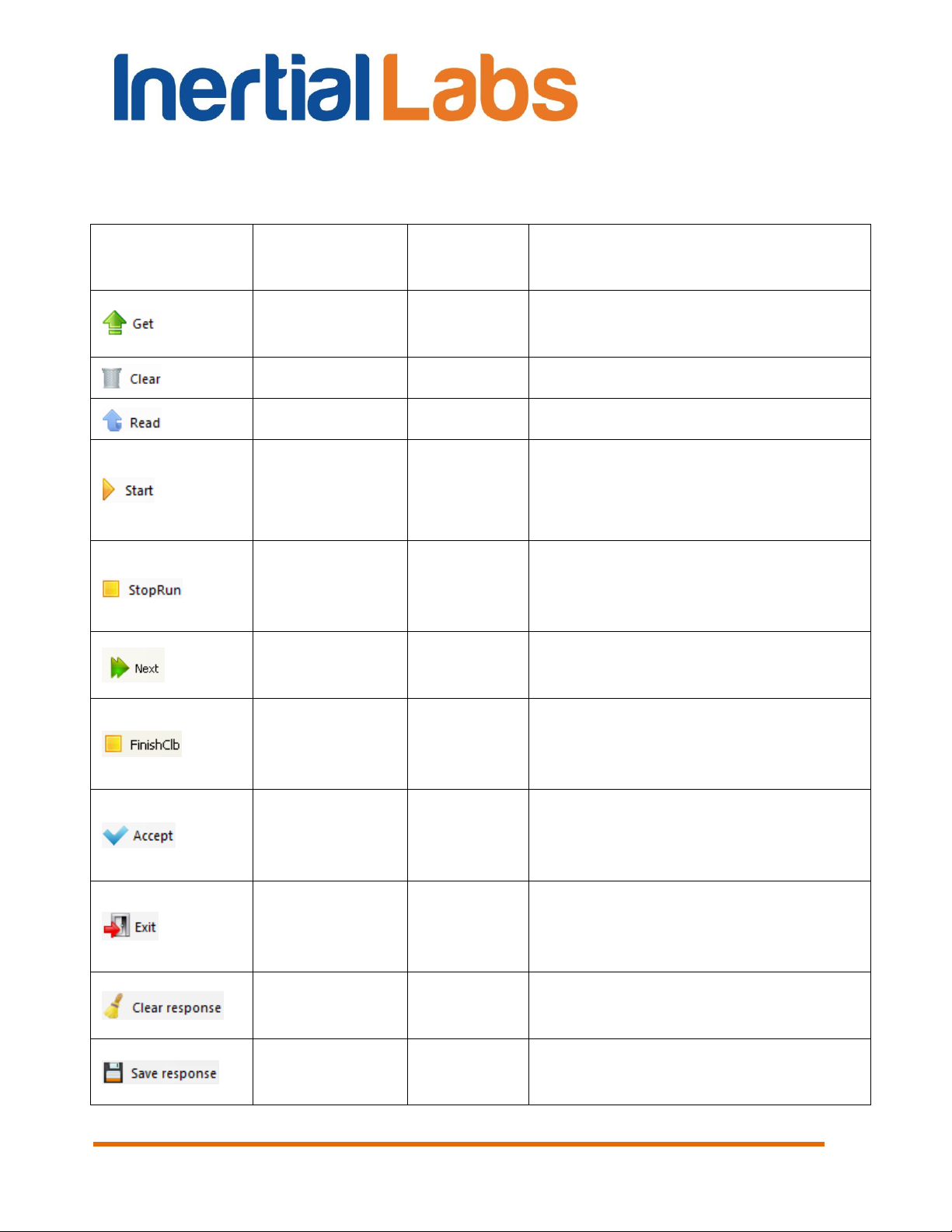
Icon
Command
Command
code
Description
GetClbRes
0x2A
Views the last calibration results
stored in the INS memory
ClearClb
0x2F
Clears calibration parameters
– – Reads out the INS flash memory
Start2DClb
Start2D2TClb
Start3DClb
StartVG3DClb
0x21
0x22
0x23
0x25
Starts the 2D, 2D-2T, 3D or
VG3D calibration
StopСlbRun
0x20
Early stops data accumulation in
the calibration run before set
accumulation time is reached
StartClbRun
0x2B
Starts new run of the 2D-2T
calibration
FinishСlb
0x2C
Finishes the calibration
procedure with multiple runs (like
2D-2T)
AcceptClb
0x2E
To accept the calibration
parameters and to save them to
the INS nonvolatile memory
ExitClb
0xFE
To exit from the calibration
without calculations and saving
calibration parameters
–
–
Clears the response window
Fig.6.2
–
–
Saves data from the response
window to *.log file
INS
GUI User’s Manual
Buttons on the toolbar are used to send commands for the INS calibration
that are described in the INS ICD. Below is list of these buttons and
corresponding commands:
87
Inertial Labs, Inc
Tel: +1 (703) 880-4222, Fax: +1 (703) 935-8377 Website: www.inertiallabs.com
TM
Address: 39959 Catoctin Ridge Street, Paeonian Springs, VA 20129 U.S.A.
Page 88
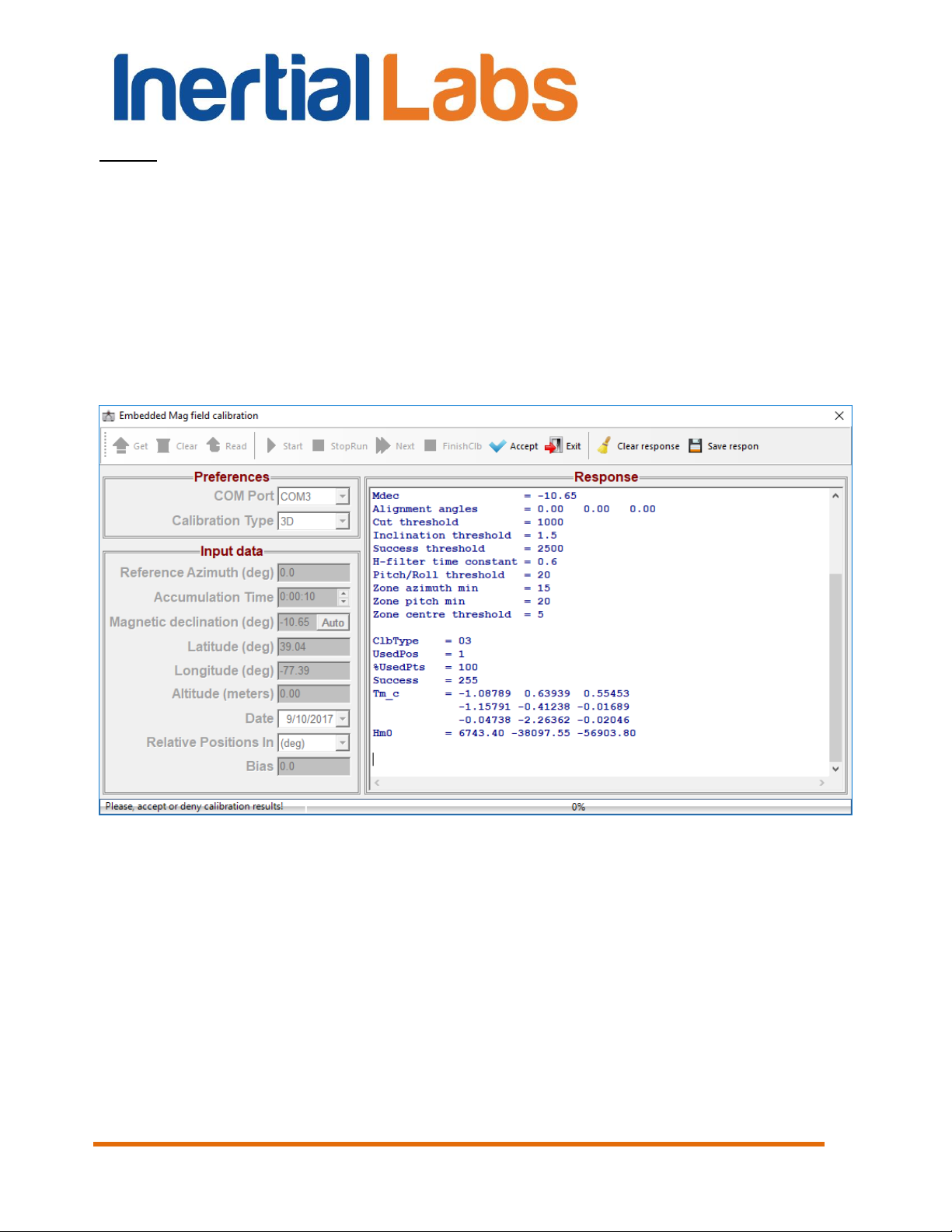
INS
GUI User’s Manual
Notes:
1. Command code in this table is payload of the command with 9-bytes structure.
2. VG3D calibration is at the testing stage. Please contact Inertial Labs about the
possibility of using the VG3D calibration.
When the INS answers on above commands then these answers appear in
the Response window (see Fig. 8.2).
Different buttons will be active depending on calibration type.
See additional document for detailed description of the embedded
calibration procedures.
Fig. 8.2
8.2. Magnetometers field calibration
Another and more convenient way for INS hard and soft iron calibration is
provided by INS GUI software.
Before calibration please check in the “Test Options” dialog box (Fig. 4.1)
correct COM port number to which the INS is connected.
Inertial Labs, Inc
Tel: +1 (703) 880-4222, Fax: +1 (703) 935-8377 Website: www.inertiallabs.com
TM
Address: 39959 Catoctin Ridge Street, Paeonian Springs, VA 20129 U.S.A.
88
Page 89

INS
GUI User’s Manual
To start the calibration select “Plugins” menu and then “Mag Field
Calibration” item (see Fig. 3.5) from the main menu. “Mag Field Calibration”
window will open (see Fig. 8.3).
Important note. For correct calibration it is necessary to set right coordinates “Latitude”,
“Longitude”, “Altitude” and “Date” in accordance with place where INS is calibrated.
Their values are set in the “Device Options” window (see Fig. 4.2).
Fig. 8.3
In the “Calibration Type” field choose from a list the type of the calibration –
2D, 2D-2T or 3D (see section 10.4 for explanation of these types).
The “Accumulation Time” field in window Fig. 8.3 sets the time which is
necessary to perform calibration procedure including at least one full 360
turn rotation in horizon plane (at least 2 full turns are recommended). This
time can be set using arrows or by entering the necessary value from a
keyboard. The default value is 60.
In “Calibration status” window the captions are highlighted that show
current states of INS calibration and actions that can be performed.
Inertial Labs, Inc
Tel: +1 (703) 880-4222, Fax: +1 (703) 935-8377 Website: www.inertiallabs.com
TM
Address: 39959 Catoctin Ridge Street, Paeonian Springs, VA 20129 U.S.A.
89
Page 90

INS
GUI User’s Manual
See section 10.4 for detailed description of the INS calibration procedure.
If place of the INS mounting on the carrier object is changed, or if the carrier
is changed, then calibration matrices for magnetometer biases and scale
factors in INS memory should be cleared by clicking on the “Clear” button
(see Fig. 8.3).
8.3. Angles accuracy
To check accuracy of the INS set precisely its attitude in orientation angles
with the help of special equipment and compare orientation angles produced
by INS with the set angles.
To start the accuracy check select “Plugins” menu and then “Angles
accuracy” item (Fig. 3.4) from the main menu. After that the next window
will appear (see Fig. 8.4).
Fig. 8.4
Inertial Labs, Inc
Tel: +1 (703) 880-4222, Fax: +1 (703) 935-8377 Website: www.inertiallabs.com
TM
Address: 39959 Catoctin Ridge Street, Paeonian Springs, VA 20129 U.S.A.
90
Page 91

INS
GUI User’s Manual
In a pull-down list in the left top corner there is an capability to choose an
orientation angle (Heading, Pitch or Roll) on which the INS will be tested.
Depending on the chosen parameter the accuracy check window name
which is shown in the Fig. 8.4 will change.
The check of the INS heading (azimuth) angle accuracy is carried out by
rotating the INS around the vertical on angles specified in the column
“Angles” Fig. 8.4.
The check of INS pitch angle accuracy is carried out by rotating the INS
around the horizontally located lateral axis X of the INS on angles specified
in the column “Angles” (see Fig. 8.4). It is necessary to note that the
accuracy control in angles 90°, 270° and close to them is not carried out
because of uncertainty of two other orientation angles – Heading and Roll in
this position.
The check of roll angle accuracy is carried out by rotating the INS around
the horizontally located longitudinal axis Y of the INS on angles specified in
the column “Angles” (see Fig. 8.4).
In the left part of check accuracy window there is a button “Devices”, by
clicking on which the window “Devices Properties” is opened (see Fig. 8.5).
In this window the operator in line “Number of Devices” sets the necessary
quantity of simultaneously tested INS units. The minimal size of parameter 1
changes on 1 by means of arrows or by keyboard necessary value input.
The size by default is 1. Then in the column “Port Name” the operator
chooses COM port number to which the INS units are connected and in a
column “Baud rate” he chooses COM-port speed which has the default value
115200 bps.
After that the operator clicks the button “Scan”. The GUI software serially
polls specified COM-ports, and in column “Device Name” names of found
INS units are displayed and button “OK” becomes active. By clicking the
button “OK” (see Fig. 8.5) names found in window “Devices Properties” are
transferred to the left of a check accuracy window (Fig. 8.4) instead of label
“NoName”. Clicking the button “Cancel” or button “X” closes the window
"Devices Properties” Fig. 8.5.
In a check accuracy window there are control buttons. The button “Angles”
opens the window “Angles Properties” Fig. 8.6, in which the operator sets
the necessary time “Accumulation Time” of data acquisition while the
Inertial Labs, Inc
Tel: +1 (703) 880-4222, Fax: +1 (703) 935-8377 Website: www.inertiallabs.com
TM
Address: 39959 Catoctin Ridge Street, Paeonian Springs, VA 20129 U.S.A.
91
Page 92

Fig. 8.5
Fig. 8.6
INS
GUI User’s Manual
measurement in each position of the INS, checks accuracy angles
“Accuracy checking points” and chooses the sensor, with the help of which
the temperature control “Temperature Sensor” will be carried out. The
minimal size of parameter “Accumulation Time” 1 changes on 1 with the
help of arrows or by means of necessary value keyboard input. The default
value is 20.
At accuracy tests it is possible to take into account misalignment angles of
the INS installation on a test bench platform on which INS is tested. Such
situation is possible if for INS installation on a test bench platform
intermediate adaptations are used, for example tilter. If deviation angles of
tilter adjusting bases for INS relatively to test bench platform are known,
they are necessary for considering at accuracy check. For this purpose
“Tilter” fields are used in the right bottom window corner Fig. 8.4. Here it is
possible:
- “(None)” is not to consider deviations of bases;
- “(Auto)” is to consider deviations for tilter used for Inertial Labs internal
tests “Tilter №” and a corresponding cell (“Position”) in this tilter;
Inertial Labs, Inc
Tel: +1 (703) 880-4222, Fax: +1 (703) 935-8377 Website: www.inertiallabs.com
92
TM
Address: 39959 Catoctin Ridge Street, Paeonian Springs, VA 20129 U.S.A.
Page 93

INS
GUI User’s Manual
- “(Manual)” is to consider manually bases deviation angles on
corresponding angles “”, “” и “”.
Fields “Tilter” are used by the developer for internal tests of the INS. The
question on their use for external tests should be coordinated with the
developer – Inertial Labs company.
The button “Accumulate Data” (see Fig. 8.4) consistently starts INS units for
operation. Automatically, in the top part of the check accuracy window the
page “Current angle, deg” opens in which in the form of the graph the
current measured angle (Heading, Pitch or Roll) is plotted. Upon completion
of data collecting there is an averaging the measured data and switching on
a following controllable angle, and in a folder where there is file
INS_GUI.exe, the file of the report like Accuracy_*.txt is kept. It is a service
file which can be used for continuation of testing INS after any possible
failure in work. In that case for loading the previous measured data the
button “Load Data” is used.
Notes.
1. The filename Accuracy_*.txt consists of the word Accuracy_ and 8-12 numbers of
year, month, date, hour and minutes when the work was carrying out.
2. The button “Load Data” opens the standard window Windows “Open…”, in which it is
necessary to choose and download a file Accuracy_*.txt with the last measured data.
In pages “Heading, deg”, “Pitch, deg”, “Roll, deg”, “Temperature, codes” the
current same INS parameters are displayed in the form of graphs.
After the end of the accuracy test cycle the page “Angle Error, deg” is
opened automatically, where Angle is Heading, Pitch or Roll, depending on
the angle, where the test was carried out. In the page window the graph of
given angle calculation error is displayed, and the minimal and maximal
error values during the test, its root-mean-square value (RMS) are indicated.
Also standard deviation (STD) of measurement noise at last position of the
INS is displayed.
Note. Page “Current Heading, deg” changes its name on “Current Pitch, deg” or “Current
Roll, deg” and the page “Heading Error, deg” changes its name on “Pitch Error, deg” “Roll
Error, deg” depending on the chosen controlled parameter in left top corner of the
window “Accuracy” (see Fig. 8.4).
Inertial Labs, Inc
Tel: +1 (703) 880-4222, Fax: +1 (703) 935-8377 Website: www.inertiallabs.com
TM
Address: 39959 Catoctin Ridge Street, Paeonian Springs, VA 20129 U.S.A.
93
Page 94

INS
GUI User’s Manual
8.4. Magnetometers axes alignment
The Inertial LabsTM INS can be factory-preconfigured to use the external
OS3D-FG Stand Alone Magnetic Compass (SAMC) instead of on-board
magnetometers to measure components of the Earth magnetic field.
Before using external OS3D-FG SAMC, it is necessary to align the SAMC
axes with INS axes for accurate operation.
For axes alignment procedures please make sure “Serial Port” field of “Test
Options” dialog box (Fig. 4.1) shows correct COM port number to which the
INS is connected.
To perform the axes alignment, select “Mag axes alignment” item from the
main menu “Plugins” (see Fig. 3.5). “Mag axes alignment” window will open
(see Fig. 8.7).
Inertial Labs, Inc
Tel: +1 (703) 880-4222, Fax: +1 (703) 935-8377 Website: www.inertiallabs.com
TM
Address: 39959 Catoctin Ridge Street, Paeonian Springs, VA 20129 U.S.A.
94
Page 95

INS
GUI User’s Manual
Fig. 8.7
The “Accumulation Time” field in window Fig. 8.7 defines the necessary
time of data acquisition while the measurement in each position of a carrier
object. At least three positions with essentially different pitch and roll angles
are required. The “Accumulation Time” can be set using arrows or by typing
necessary value. The default value is 10 seconds.
See section 10.9 for detailed description of the INS and OS3D-FG SAMC
axes alignment procedure.
Inertial Labs, Inc
Tel: +1 (703) 880-4222, Fax: +1 (703) 935-8377 Website: www.inertiallabs.com
TM
Address: 39959 Catoctin Ridge Street, Paeonian Springs, VA 20129 U.S.A.
95
Page 96

GUI User’s Manual
9. Convert Menu
There are four items:
“Report of experiment” is used to convert saved binary data (pair of
files *.bin, *.prm to the text file;
“Convert to Raw IMU data” converts saved binary data (file *.bin) to
special binary file *.imu with raw IMU data used in the NovAtel Inertial
Explorer for post-processing of the INS and GNSS receiver data. See
section “12.2 Raw IMU data generation” for details.
“Convert log data to bin file” can be used to convert saved log data
to binary data for further conversion into text or *.imu files.
“Combine RAWIMUB and GPS data” embeds raw IMU data into
GNSS stream which can be used in the NovAtel Inertial Explorer for
post-processing of the INS and GNSS receiver data. See section
“12.2.1. Embedding raw IMU data into GNSS stream” for details.
INS
When “Report of experiment” item is selected, or button is clicked, or
F8 button is pressed (see Fig. 3.6), a standard Windows “Open” window is
opened. In this window select the *.bin files saved previously when the INS
was operating in its ordinary mode. Consequently, a report file with same
name but with .txt extension is created. Note that file with an extension .prm
and the same name as .bin should be present as well.
The “Report of experiment” creates text file according to the output data
format of data in the binary *.bin file. Necessary data format is set by user in
the “Test Options” window. Description of the text file is done in the
“Appendix C.2. Text presentation of output data formats”.
«Convert log data to bin file» is useful if data were saved directly to a log
file as output from the INS COM port, without use of INS GUI software. In
this case saved log contains also headers, check sum and other service
data according to the INS message structure. Use «Convert log data to bin
file» to convert log file to binary files *.bin, *.prm which can be processed by
INS GUI software.
After select the «Convert log data to bin file» item a standard Windows
«Open» window appears. In this window please select parameters file *.prm
Inertial Labs, Inc
Tel: +1 (703) 880-4222, Fax: +1 (703) 935-8377 Website: www.inertiallabs.com
TM
Address: 39959 Catoctin Ridge Street, Paeonian Springs, VA 20129 U.S.A.
96
Page 97

INS
GUI User’s Manual
with current parameters of the INS unit. Then new Windows «Open»
window is opened where user is asked to select the log file. After this the
pair *.bin, *.prm files will be created with the same name as log file plus
“_Converted” text. Then you can convert this pair *.bin, *.prm files to text file
using the «Report of experiment» item.
Inertial Labs, Inc
Tel: +1 (703) 880-4222, Fax: +1 (703) 935-8377 Website: www.inertiallabs.com
TM
Address: 39959 Catoctin Ridge Street, Paeonian Springs, VA 20129 U.S.A.
97
Page 98

INS
GUI User’s Manual
10. The INS operation
10.1. The main operation modes of the INS
Step 1. Connect data transfer cable to the INS. Connect the other end
of the data transfer cable to either COM port or USB port of the host
computer. If connection between the computer and the INS is done through
a USB port, a driver for a COM-to-USB converter needs to be installed. See
Appendix A ‘Installation of the COM-to-USB converter drivers and
configuration of PC parameters’ for details on the installation procedure. If it
is connected to a standard PC COM port, then there are no needs to install
any drivers. Note that INS manufacturer guarantees reliable operation of the
INS if it is connected directly to the COM port.
Connect an active GNSS antenna to the INS TNC connector.
After power on the INS LED indicator lights yellow. After completing of
initialization of the onboard GNSS receiver (about 25 sec) the LED indicator
lights red and the INS is ready for operation.
Step 2. Start INS_GUI.exe file to begin working with the GUI software.
The main menu will appear (Fig. 3.1).
Step 3. Select “Test options…” from the “Options” menu (see Fig.
3.7) or click button. “Test option” window (Fig. 4.1) will open.
Step 4. Set the correct СОМ port number in the “Serial port” field and
its baud rate as Fig. 4.1 shows.
Step 5. (Not obligatory) In “Test option” window (Fig. 4.1), if you need,
you can set “Record time” of data writing when data is being saved to file
and “Number data for average” (the quantity of averaged data) that can be
used for smoothing of viewed data. Note that averaging relates to the data
output on the screen only and is not applied to the data written in a file.
Note: To find the number of the СОМ port to which the INS is connected, see “2.
Installation of drivers and configuration of the PC parameters” and “Appendix А.
Installation of the COM-to-USB converter drivers and configuration of the PC
parameters”.
Inertial Labs, Inc
Tel: +1 (703) 880-4222, Fax: +1 (703) 935-8377 Website: www.inertiallabs.com
TM
Address: 39959 Catoctin Ridge Street, Paeonian Springs, VA 20129 U.S.A.
98
Page 99

INS
GUI User’s Manual
Step 6. In “Test option” window (Fig. 4.1) set (check) data output mode
in the “Operating Mode” group, and also “Output Data Format” (see
Appendix B for more information on the output data format). Click “ОК”.
Step 7. (Not obligatory) If you want to change some parameters of the
INS or its operation select “Device options…” or “Swaying compensation
options…” from the “Options” menu – see Fig. 3.7. Appropriate window
(Fig. 4.2 or Fig. 4.20) will open. Set the necessary INS operation
parameters. Click “ОК”.
Step 8. Select “INS Visualization” from the “Run” menu (Fig. 3.3) or
click button on the toolbar, or press F4. The window shown in Fig. 5.1 will
appear. You can switch to other visualization style by clicking on its preview
on the tab. Depending on the selected style windows shown in Fig. 5.3 –
Fig. 5.5 will appear.
Step 9. Click “Start” button. Initial alignment of the INS will start.
This is signified by the message “Initial alignment. Please wait”. Also a
progress bar of initial alignment will appear in the status line of the main
window. During the initial alignment the INS has to be unmovable relative to
the Earth. Once the initial alignment time is over, observe changes in
numeric data and graphical evolutions of the object.
Note: For visual convenience of INS position perception displayed on the monitor and
the INS real position, it is recommended to place the INS in parallel with the monitor
before the beginning of work as follows: direct lateral axis X to the monitor and direct
longitudinal axis Y in parallel with the monitor on the left.
Step 10. If you have selected “On Request” operating mode, click
“Request” button to get data from the INS each time if you want.
Observe changes in numeric data and graphical evolutions of the object.
Step 11. To save data click “Write” button. Caption “Data are
writing in file!” will appear. Also a progress bar of data writing and timer will
appear in the status line of the main window.
In “On Request” operating mode data are written in file sequentially with the
each clicking “Request” button.
Note: To allow data sawing the appropriate checkbox should be set in the “Test
Options” window (see Fig. 4.1).
Inertial Labs, Inc
Tel: +1 (703) 880-4222, Fax: +1 (703) 935-8377 Website: www.inertiallabs.com
TM
Address: 39959 Catoctin Ridge Street, Paeonian Springs, VA 20129 U.S.A.
99
Page 100

INS
GUI User’s Manual
Step 12. To stop readout and data displaying click “Stop” button. If
the data were written in a file then the writing stops too.
Default directory for saved files is “data” subdirectory placed in the directory
where file INS_GUI_*.exe is located. Default name of file with saved data is
generated automatically and consists of the INS serial number, date and
time digits separated by dash symbols where the first 4 digits are the year,
the next 2 digits are the month, then 2 digits of day, next digits are hours,
minutes and seconds of operation start. At the saving data, two files of the
same name with .bin and .prm extensions are saved in the specified folder.
In .bin files the measured data is saved, and in .prm files the INS
microprocessor parameters, at which this data was obtained, are saved. For
example, A1240013-2012-11-20-12-14-26.bin corresponds to data saved
from the INS s/n A1240013 on 2012, November 20th, 2012, at 12:14:26.
Note. You can preset name of file for data writing. For this select item “Save as” in the
“File” menu and enter desirable file name.
Step 13. Repeat Step 9 – Step 12 as many times as you need.
Step 14. To close standard operation mode window (Fig. 5.1 – Fig.
5.5) click the icon in the title of current tab.
Step 15. Select “Stop INS” (Fig. 3.3) from the “Run” menu, or click
button.
To get the saved data as text file, do the following:
Step 16. Select “Report of experiment” from the “Convert“ menu
(Fig. 3.6) or press F8 in the main menu or click button (Fig. 3.1). A
standard Windows “Open” window will open.
Step 17. Select the necessary file with extension .bin. Click “ОК”. A .txt
file will be created with the same name and in the same folder as the
selected .bin file, with format set in Step 6.
Note. When large file data is processed then some time is necessary for text file saving.
If you will start new operations with GUI software before end of text file saving, then GUI
software will appear as not responding or locked. Just wait some time for saving end,
after that GUI software will be unlocked.
Inertial Labs, Inc
Tel: +1 (703) 880-4222, Fax: +1 (703) 935-8377 Website: www.inertiallabs.com
TM
Address: 39959 Catoctin Ridge Street, Paeonian Springs, VA 20129 U.S.A.
100
 Loading...