

Page 1
© 2014 Inepro B.V. All rights reserved
Technical Manual | Inepro IP Reader V2
Inepro IP Reader V2
Product Version: Rev.3 - V2
Version of this manual: 2.1.1
Page 2

Page 3
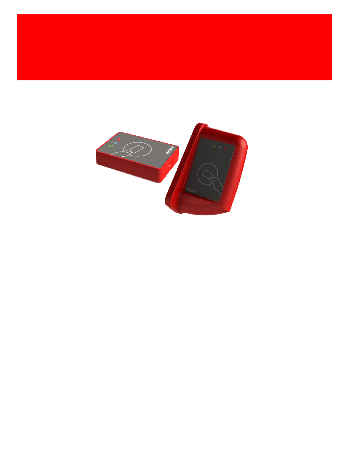
Inepro IP Reader V2
Congratulations on your selection of Inepro card readers. We are certain you will be
pleased with your purchase of one of the flexibele solutions of the market.
We want to help you get the best result from your Inepro Back Office Suite. This manual
contains information on how to do that; please read it carefully. Due to continuous
product improvements this manual is subject to changes without notice.
We strongly recommend you read the license agreement to fully understand its coverage
and your responsibilities of ownership.
Your Inepro dealer is dedicated to your satisfaction and will be pleased to answer your
questions and your concerns.
Best wishes,
Inepro BV.
The most versatile card reader solution
Page 4

All rights reserved. No parts of this work may be reproduced in any form or by any means graphic, electronic, or mechanical, including photocopying, recording, taping, or information
storage and retrieval systems - without the written permission of the publisher.
Products that are referred to in this document may be either trademarks and/or registered
trademarks of the respective owners. The publisher and the author make no claim to these
trademarks.
While every precaution has been taken in the preparation of this document, the publisher and
the author assume no responsibility for errors or omissions, or for damages resulting from the
use of information contained in this document or from the use of programs and source code that
may accompany it. In no event shall the publisher and the author be liable for any loss of profit
or any other commercial damage caused or alleged to have been caused directly or indirectly by
this document.
Version 2.1.1 created: October 2014 in Nieuw-Vennep.
Publisher
Managing Editor
Technical Editors
Cover Design
Inepro B.V.
K. de Graaf
P. Blom
K. de Graaf
Production
Inepro B.V.
Team Coordinator
R. Groen
H. Wagenaar
Inepro IP Reader V2
R. de Koker
Inepro IP Reader V2
Page 5

http://www.inepro.com
Table of Contents
Introduction
2
Components
4
Operating Procedures
8
Network Connections
10
LEDs (Light Emitting Diodes)
14
Hardware installation
20
Software configuration settings
26
Specifications
32
Appendix I
38
Page 6

Page 7
ATTENTION!!
Read this manual carefully before installing the IP Reader!
Mains connection
Guarentee
Security
Before connecting the appliance to the mains, check that the mains supply voltage corresponds
to the voltage printed on the type plate of the adapter. If the mains voltage is different, consult
your supplier.
No guarantee can be given if safety regulations are not followed.
Always disconnect the power supply before handling anything inside the device.
This device is in conformity with the EMC directive and low-voltage directive.
CE Conformité Europeène (Conform European Norm)
End of life directives
Inepro is paying a lot of attention to environmentally-friendly production. Your new device contain
materials which can be recycled and reused. At the end of its life specialised companies can
dismantle the discarded device to recycle the reusable materials and to minimise the amount of
materials to be disposed of. Please observe the local regulations regarding the disposal of
packaging materials, exhausted batteries and old equipment.
This device may only be used indoors.
Indoor User Only
Directives
Version 2.1.1 - I
Page 8

Page 9

I
Introduction
Part
Page 10

2 - Inepro IP Reader V2
Introduction
In this manual you find the instructions to install and configure your
IP-reader. This manual is meant for all the Inepro IP-readers.
This manual, the IP reader hardware and software are subject to
change, make sure you have the latest version of this manual,
because the older versions may have become obsolete.
Function
The purpose of the IP reader is to read the unique ID contained in
the card that is presented to the reader and transfer this ID to a
server. In most cases this data will be the card serial number. To
facilitate this a variety of card reader software module have been
developed. Our configuration tool will enable you to change the
setting on the IP reader board.
Page 11

II
Components
Part
Page 12
4 - Inepro IP Reader V2
Components
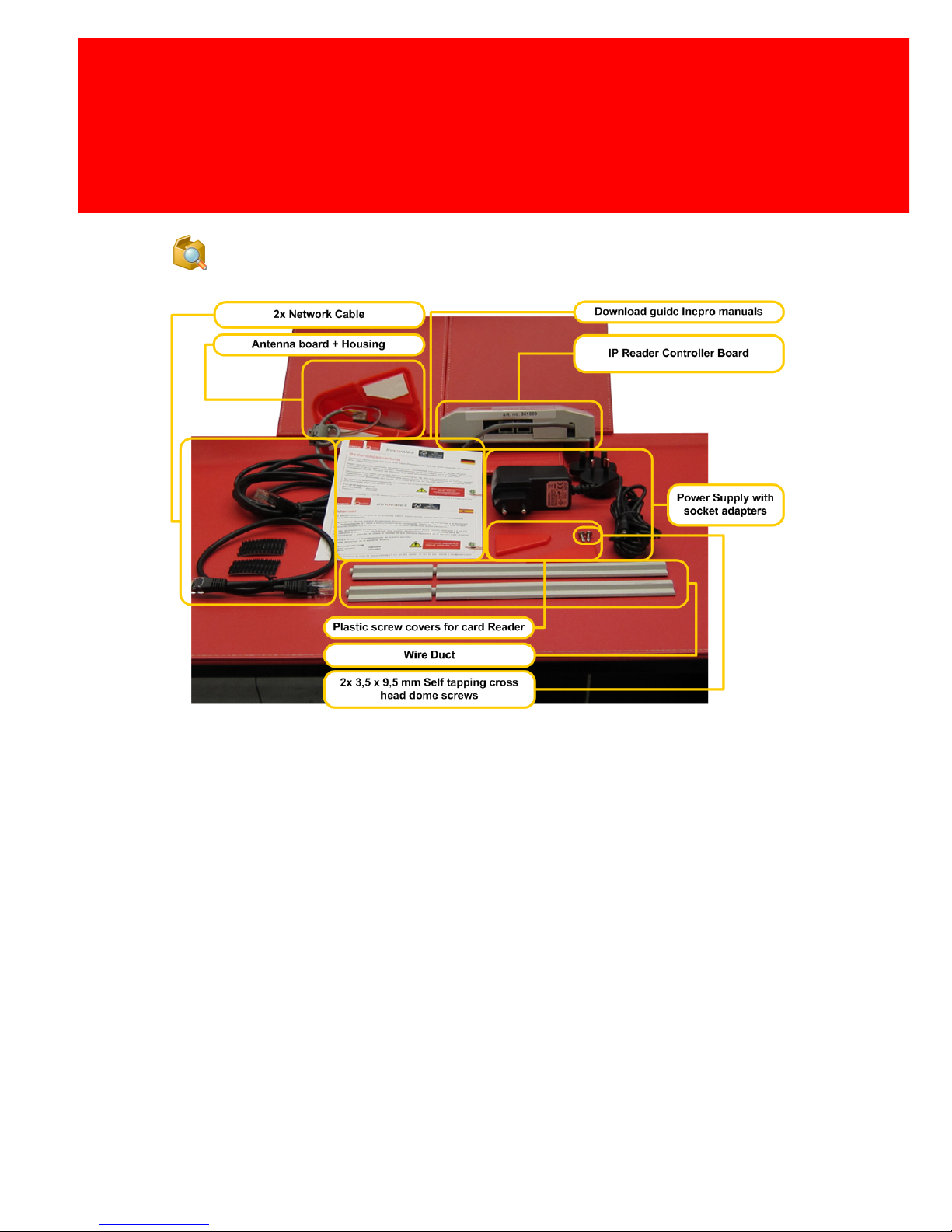
The IP Reader consists of the following components:
· Red Card Reader Housing
-
Red Antenna Box
-
Antenna Box Cap 1 / Red
-
Antenna Box Cap 2 / Red
· Controller Box
· Wire Duct - Grey
· Network Cables
-
Network Cable UTP C5E Patch Black (0,5mtr.)
-
Network Cable UTP C5E Patch Black (2,0mtr.)
· Power Supply AC/DC 12 Volts, 7 Watt
-
Power Supply Unit
-
3x Socket Adapter
Page 13

Components
Version 2.1.1 - 5
· Screw set
-
2x Screw self tapping cross head dome 3,5 x 9,5 mm
· Download Guide Inepro Manuals
Check Components
Please check if all the components are in the set before you
continue with the installation and setup.
Some parts are already pre-assembled or have already be
mounted. Like the Antenna board that is mounted in the
pre-assembled Red Card Reader housing (the red antenna box).
Page 14

Page 15

III
Operating Procedures
Part
Page 16
8 - Inepro IP Reader V2
Operating Procedures
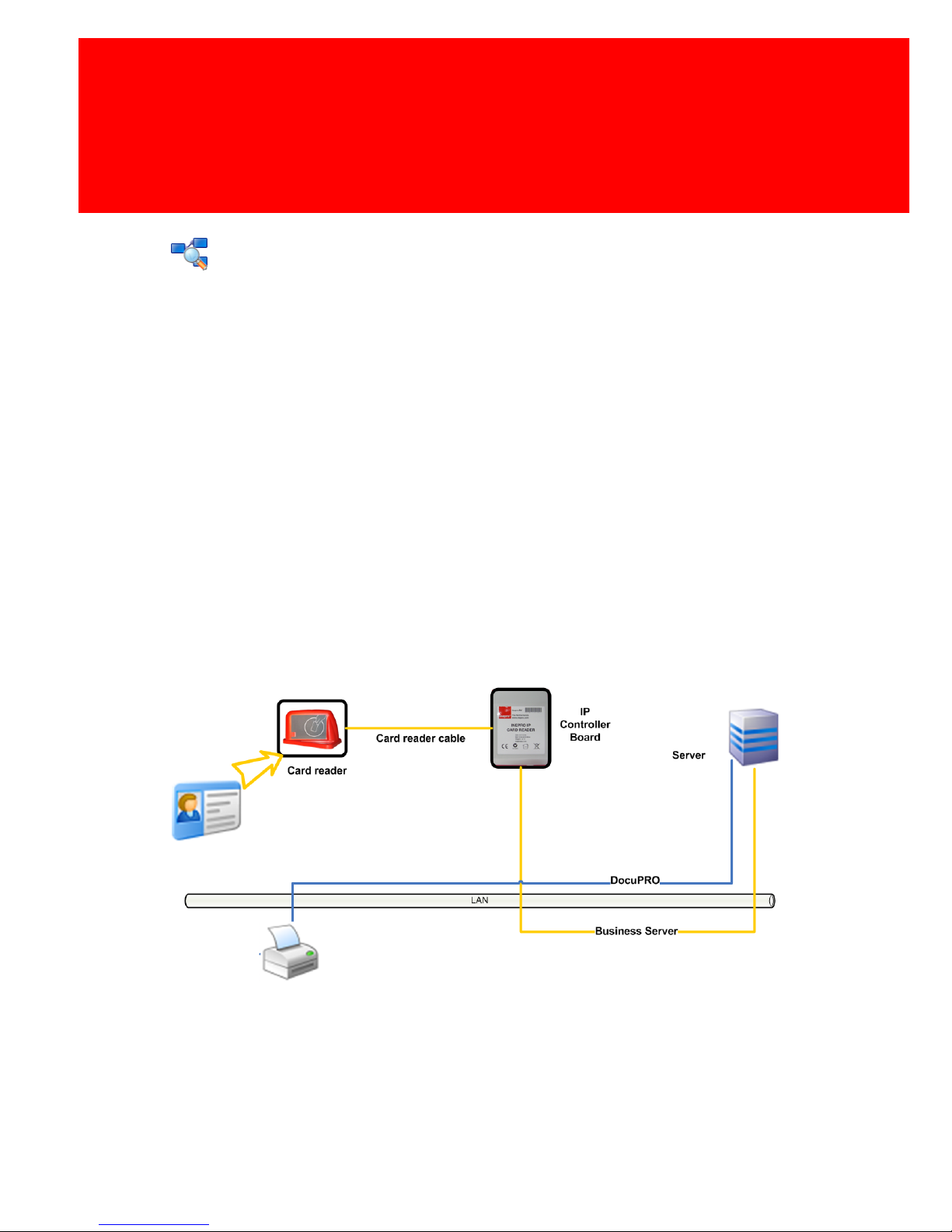
The card reader is connected to the IP controller board by the card
reader cable. Using this cable the IP controller board
communicates with the card reader. When a card is presented to
the reader it will read the card’s data. The IP controller board
makes a request to the card reader for the data. The IP controller
board will then transfer this information to the server by means of
an Ethernet connection. The server will receive the card’s data and
returns an (error) code to the IP controller board. The IP controller
board will show this code through the LED's in the card reader’s
housing.
Page 17

IV
Network Connections
Part
Page 18

10 - Inepro IP Reader V2
Network Connections
Switch
On the IP controller board there are two network connectors. The
IP controller board can be used as a switch because of the
Ethernet switch chip on board and can be placed between a wall
outlet and an existing Ethernet device (like a printer or
multifunctional device).
Power over Ethernet (PoE)
If the power supply adapter is used both connectors can be used
normally to connect to the wall outlet and the Ethernet device. But
the IP controller board can also be supplied with energy by a Power
over Ethernet switch. In this case the connection from the PoE
switch must be made to the "PoE" Ethernet connector, the Ethernet
device can be connected to the "no PoE" connector.
If the cables are connected falsely (ie. the PoE switch is
connected to the "no PoE" Ethernet connector), nothing will be
damaged. In that case the IP controller won't have energy and will
not operate. Switching the Ethernet cable to the "PoE" connector
will activate the IP controller board.
Page 19
Network Connections
Version 2.1.1 - 11
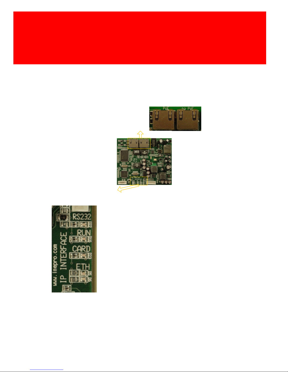
IP READER OVERVIEW
Power over Ethernet
No Power over
Ethernet
Orange LED = Blinking
Green LED = On
Orange LED = On
Green LED = Blinking
IP Controller Board
Ethernet
Connections
IP Controller Board
IP Controller Board LED's
-->
-->
-->
-->
-->
RS232 Led on = Communication between
card reader and controller board is OK.
RUN led on = Program in the micro on the IP
controller board runs correctly.
CARD led on = controller board detects card
being presented to card reader.
Green led on = Ethernet connection with
internal switch chip
Orange led blinking = data being transferred
trough Ethernet connection
Page 20

Page 21

V
LEDs (Light Emitting Diodes)
Part
Page 22
14 - Inepro IP Reader V2
LEDs (Light Emitting Diodes)
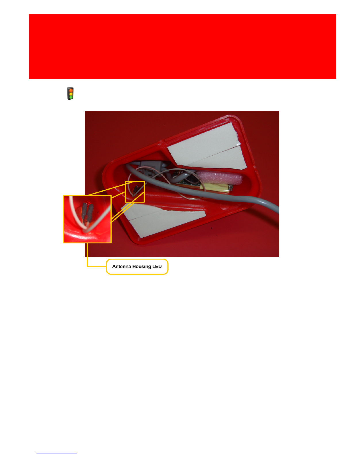
Antenna Housing LED
Inside the card reader’s housing a LED is mounted which can be
used to let the user know that card data has been read and this
data is presented to the server. The LED will also be used to show
an error has occurred, by using different blink patterns.
Blink patterns
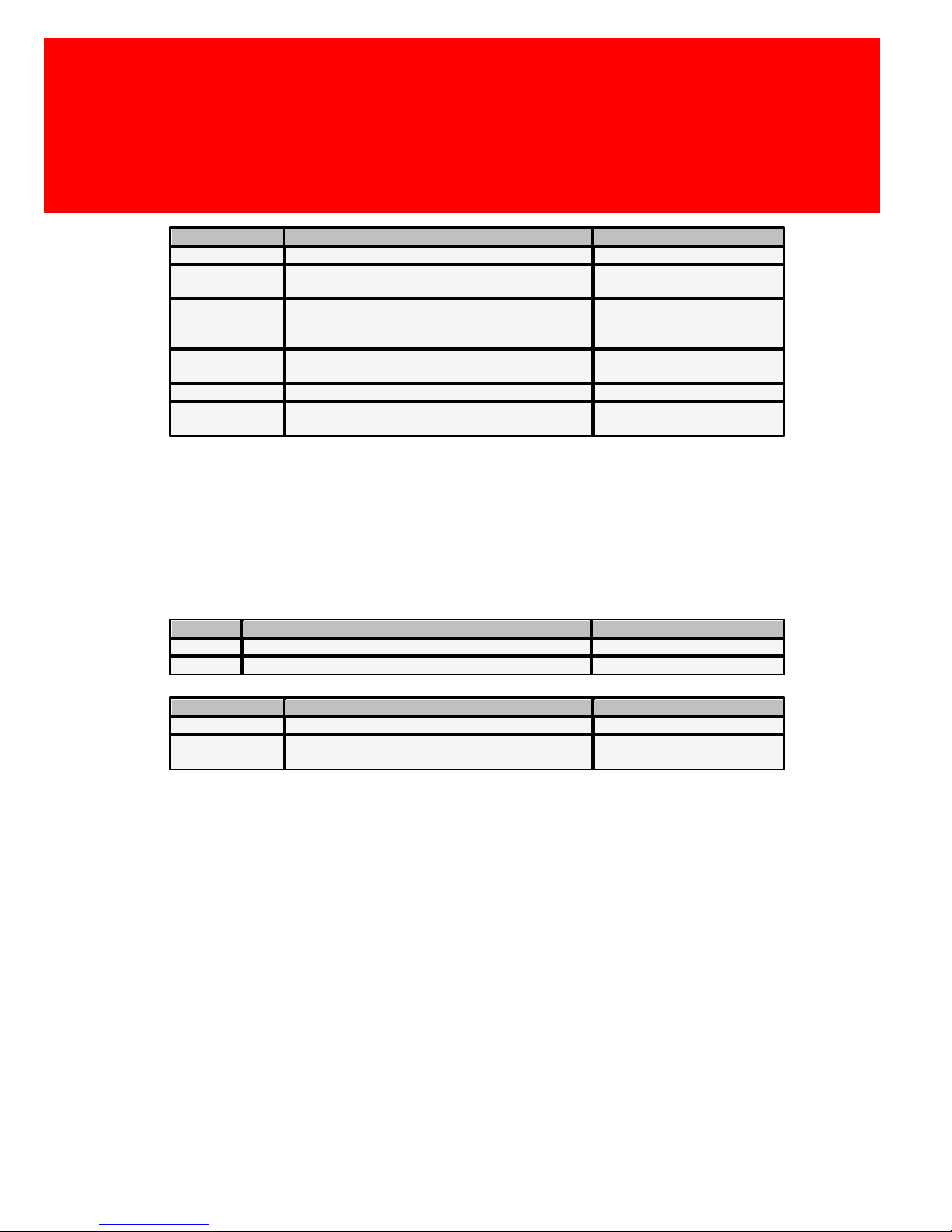
In case of an error situation the LED will blink with an irregular
pattern.
The number of times the LED blinks between the longer 'on' (or
'off') pulses is an indication for the error code.
Page 23
LEDs (Light Emitting Diodes)
Version 2.1.1 - 15
Reader
Status
Display
All
Waiting
Off
Non-Wiegand
Card presented to reader, but no reaction from
server
Contant on/off pattern
(0.5 sec. / 0.5 sec.)
Wiegand
Card presented to reader, but no reaction from
server
Contant on/off pattern
(0.5 sec. / 0.5 sec.) for 30
seconds.
Non-Wiegand
Card accepted, card data presented to server
and accepted at the server.
On
Wiegand
Card read, but not accepted
Short pulse (<0.5 seconds)
Wiegand
Card presented correctly, server received the
data OK
Long pulse (2-4 seconds)
Error Codes
Also the server can generate error codes. These error codes are
shown when the card lies on the card reader. This error code will
enable the user to communicate the type of error without the
necessity of a service engineer to be present at the reader’s site.
Symbol
Description
LED
-
Header or trailer of an error code
Long Pulse
.
Error code
Short Pulse
Reader
Status
Code
Non-Wiegand
Card reader not responding
9 error pulses (-.........-)
All
Error in the EEPROM configuration of IP
Controller board
10 error pulses (-..........-)
Page 24
16 - Inepro IP Reader V2
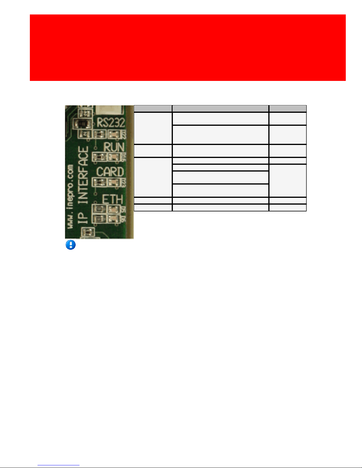
IP Controller Board LED's
LED
Status
Display
RS232
Connection between card reader and
IP Controller board.
Off
Card reader (that does not allow
access actively), sends data to the IP
controller board. *1
On
RUN
Running OK
Blink every
0.5 sec.
CARD
Card present
On
Card not present
Off
Card reader cannot be actively
accessed *1
The card data was presented to the
server 2 seconds ago.
ETH Green
Running OK
On
ETH Orange
Running OK
Blinking
Footnotes:
*1.
There are card readers that have a protocol installed where the controller board does
not have to establish an active connection with the card reader. The card reader itself
will generate a data string containing the card number. The IP controller board will
receive this data string and, after encryption, redirect this data to the server. This
situation can cause the CARD LED and the RS232 LED to behave differently.
Page 25
LEDs (Light Emitting Diodes)
Version 2.1.1 - 17
IP Controller Board Ethernet Connector LED's
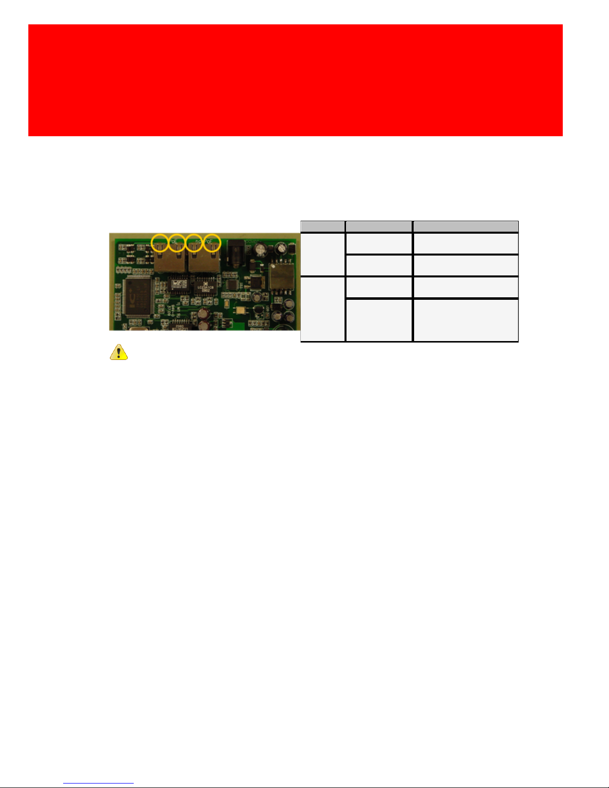
On each of the 2 Ethernet connectors on the IP controller board 2
LEDs are mounted with the same way of operating as a network
switch/router.
LED
Status
Display
Green
(or
orange
PoE)
Connection
exists
On
Connection
does not exist
Off
Orange
(or green
PoE)
Data is being
transmitted
Blinking at transmission
speed
Bad or slow
connection
Blinking at moderate
speed, modulated on the
data transmission blink
signal
With the PoE connector, the status of the green LED will be
that of the orange LED and vice versa.
Page 26

Page 27

VI
Hardware installation
Part
Page 28
20 - Inepro IP Reader V2
Hardware installation
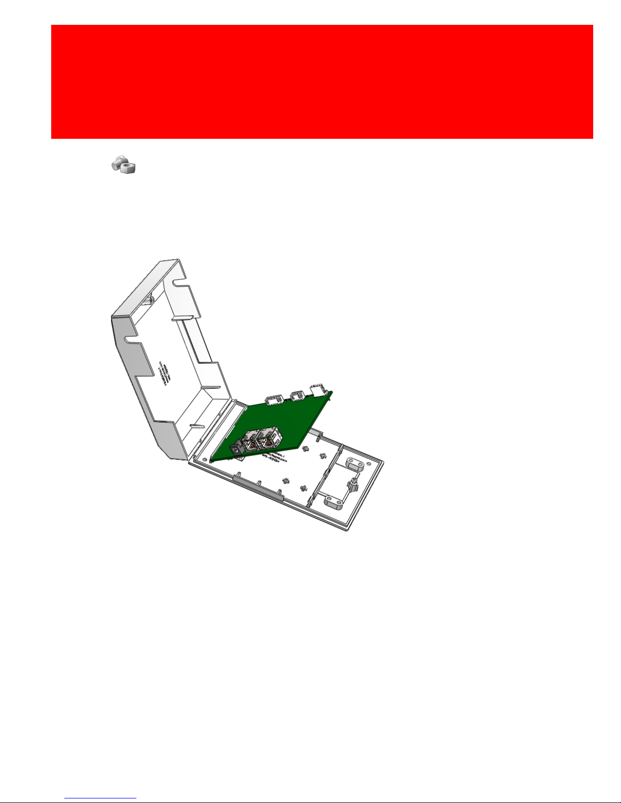
· Make sure the print board is securely connected in
the housing.
· Connect the antenne board to the IP Reader Print
board and use the cable clip to secure the cable to
the housing.
Page 29
Hardware installation
Version 2.1.1 - 21
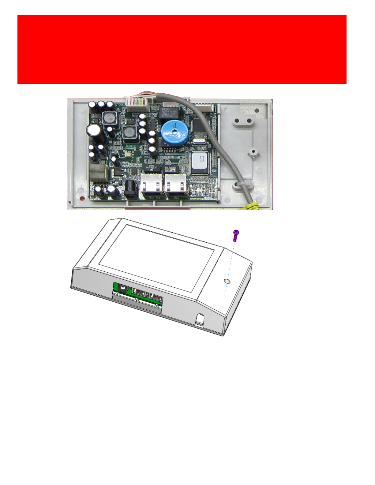
Network with PoE (power over Internet)
· Connect the network cable to the network connector
marked PoE (the rightmost network connector in the
picture above).
Page 30

22 - Inepro IP Reader V2
Network without PoE (normal network connection)
· Connect the network cable to the network connector
marked no PoE (the rightmost network connector in
the picture above).
· Place the power adapter cable in the black connector
(shown on the left)
· Connect the adapter to a power socket.
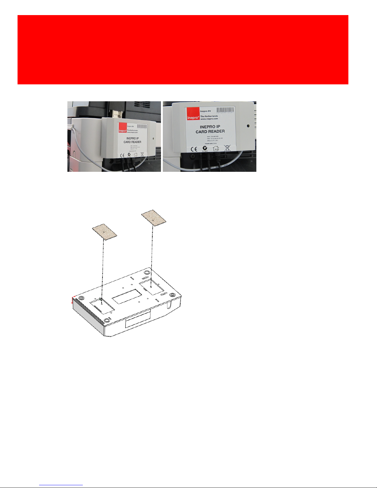
Place the Card Reader
· Stick the reader with the adhesive tape to the side of
the machine and / or use the screws to attach it even
more firmly.
· Place the cover over the screw holes.
· Strip the protection from the adhesive tape and use
(parts) of the cable guides, to guide the cable to the
back of the machine.
Page 31
Hardware installation
Version 2.1.1 - 23
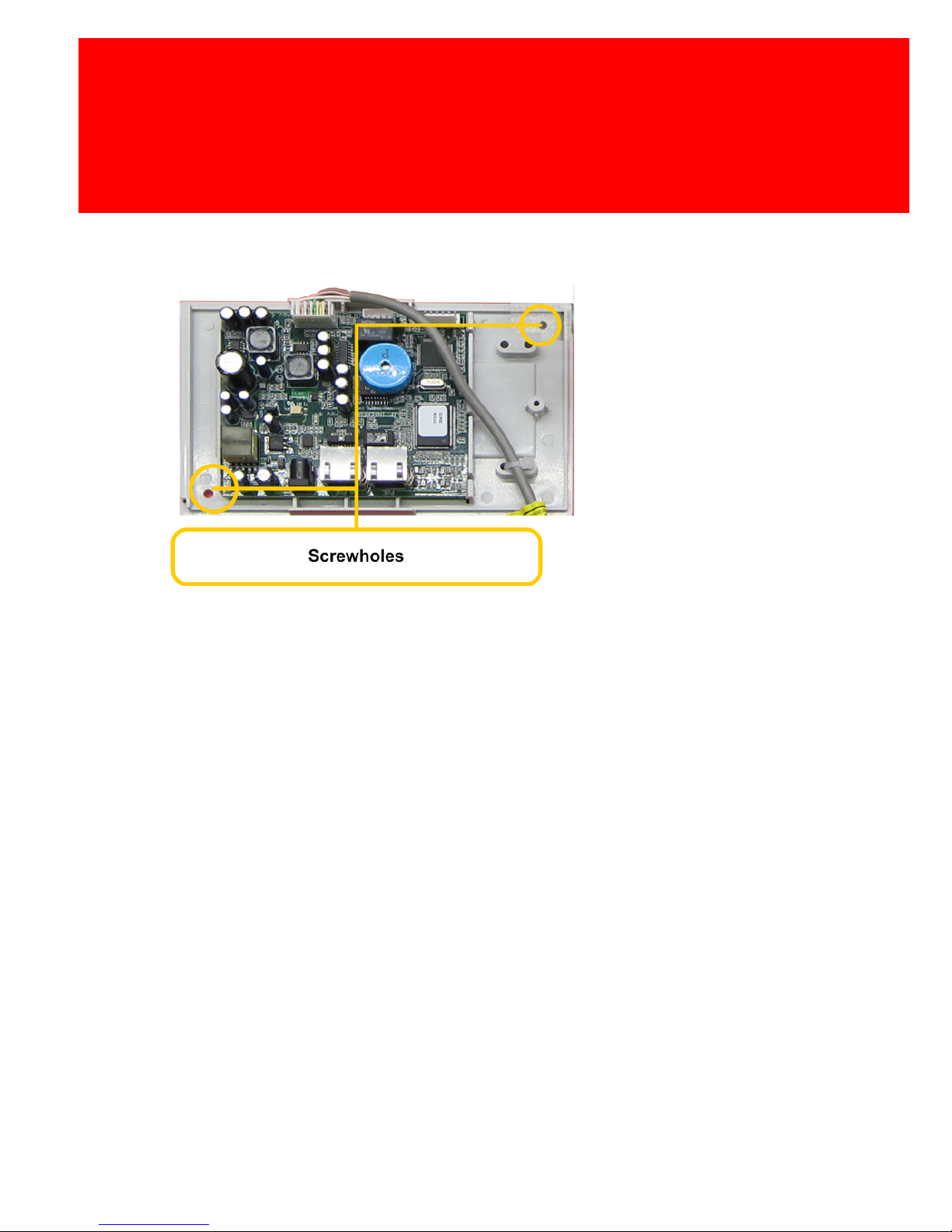
Place the IP-Card Reader print board
Attachment the IP-Card Reader print board with
Velcro
· Clean the surface of the machine and the covers.
· Place the velcro on the covers and the machine.
· Place the IP-Reader Board on the velcro on the
machine.
Page 32
24 - Inepro IP Reader V2
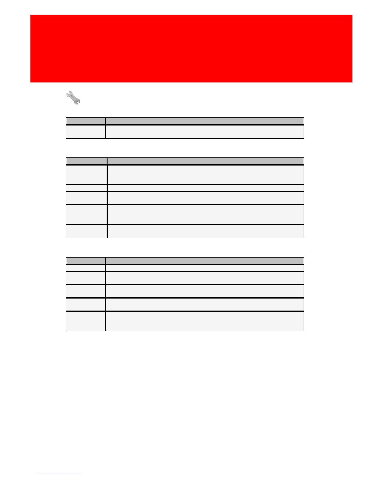
Attachment the IP-Card Reader print board with
screws
· Use the two self tapping screws to secure the bottom
cover to the machine.
Page 33

VII
Software configuration settings
Part
Page 34
26 - Inepro IP Reader V2
Software configuration settings
Name
Key
Description
Name
The name of this IP reader (like 'Printer Q745') This name will also be used as
host name, it is sent to the DHCP server and DNS server if they are enabled.
IP config
Key
Description
Dynamic Host
Configuration
Protocol
Enabled if DHCP be used, disabled if the network information need to be filled
out manually.
IP
The IP-address for the IP reader.
Netmask
The netmask (only used when using subnetting, ask your system administrator,
if you're not sure). Standard value 255.255.255.0
Gateway
The IP address of the gateway (The gateway is de server that is located
between two networks, like the Internet and your local network). It is usually the
same address as the DNS server.
Domain Name
System
The IP address of the server with the Domain Name System, the system that
transforms names to IP-addresses and vice versa.
Server config settings
Key
Description
Server 1 IP
The address of the server that the IP reader should contact.
Server 2 IP
The address of the back-up server that the IP reader should contact. It will be
contacted if the first server does not respond.
Server 1 name
When DNS is used the name of the server can be entered, the IP-address
value for this server will be ignored, and retrieved from the DNS server.
Server 2 name
When DNS is used the name of the server can be entered, the IP-address
value for this server will be ignored, and retrieved from the DNS server
Key set
Key set will give the possibility to set the encryption key between the IP reader
and the server. At the time of writing the value as not yet used and should
always be set to '1'.
Page 35
Software configuration settings
Version 2.1.1 - 27
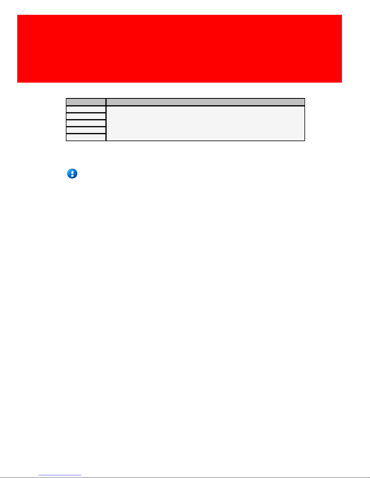
Reader config settings
Key
Description
Setting 1
These settings will be addressed below.
Setting 2
Setting 3
Data 1
Data 2
These fields will be used for retrieving the card reader data. The
values entered here are dependent on the card that is used.
Note: The raw data is supplied without conversion. Below you
will find the data that applies to the data supplied in a decimal
format.
Page 36
28 - Inepro IP Reader V2
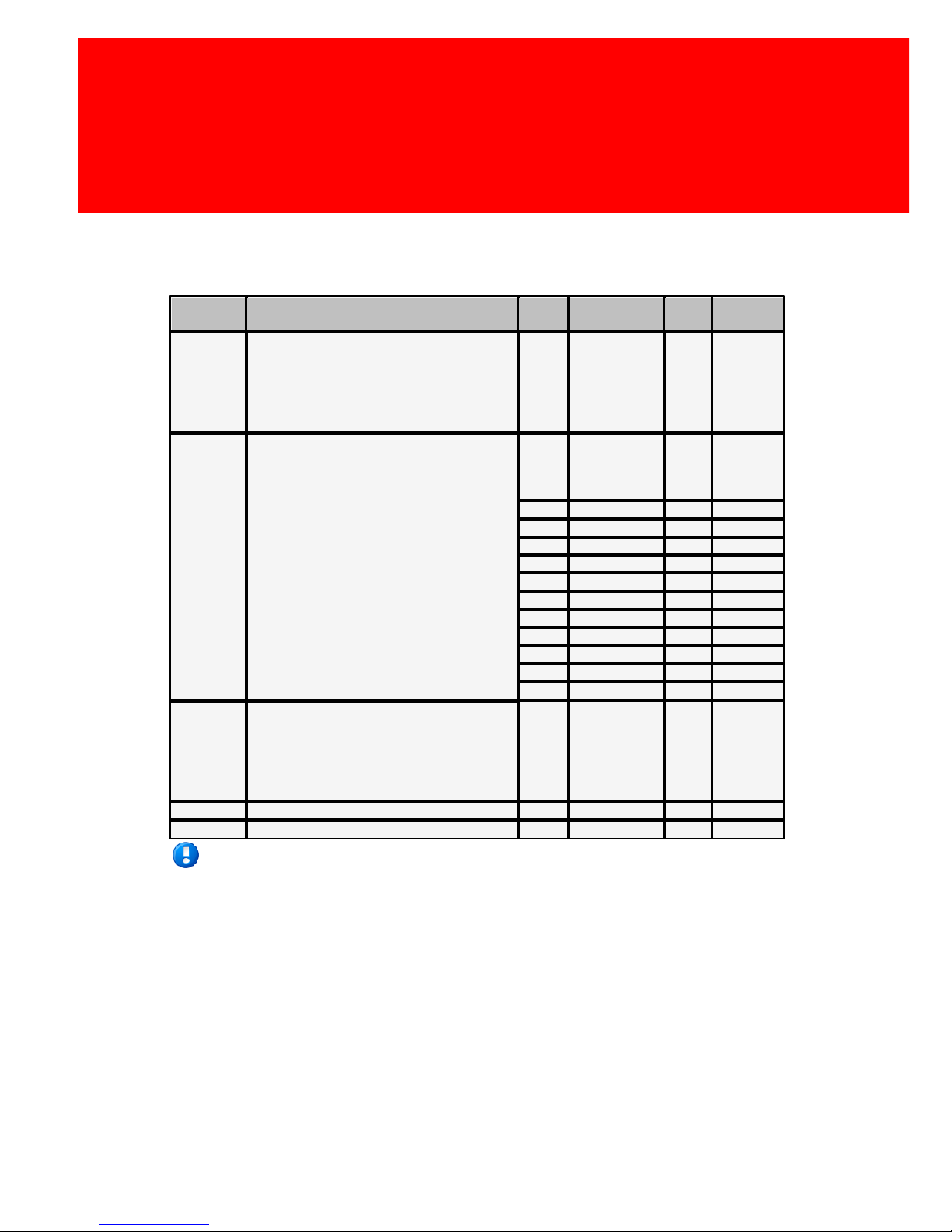
These are the setting for the currently supported readers:
Wiegand:
Setting
Description
Value
Description
Bits
Facility
code
Setting 1
Card ID. Because of the applied
interface it is possible that different
card readers are connected with this
communication protocol. To be able to
differentiate the different card type the
card type can be entered here.
---
-
Setting 2
Protocol Type. The different Wiegand
readers are able to read card with
different protocols. The IP reader
software will enable you to select one
of the protocols.
(Remark ”all types” in setting 0 means
All types except 2 and 128-255.)
0
All types
except value
2 and
128-255
-
1
H10301
26
8 bit2H10302
37
none
3
H10304
37
16 bit
4
H10306
34
16 bit
5
C1000
35
12 bit
8
ARAS 36
36
16 bit
128
NFP3716 bit
129
NFP1
36
15 bit
130
PAL340 bit
131
PAH270 bit
255
RAW
--
0 bit
Setting 3
Facility code. This is a part of the data
delivered by the Wiegand protocol. If
the value here is other then '0', then
the IP reader will check if the code on
the card is present. If the value is '0'
the facility code is not checked.
---
-
Data 1
Not applicable
----Data 2
Not applicable
---
-
Note: The facility code is never send to the server.
Page 37
Software configuration settings
Version 2.1.1 - 29
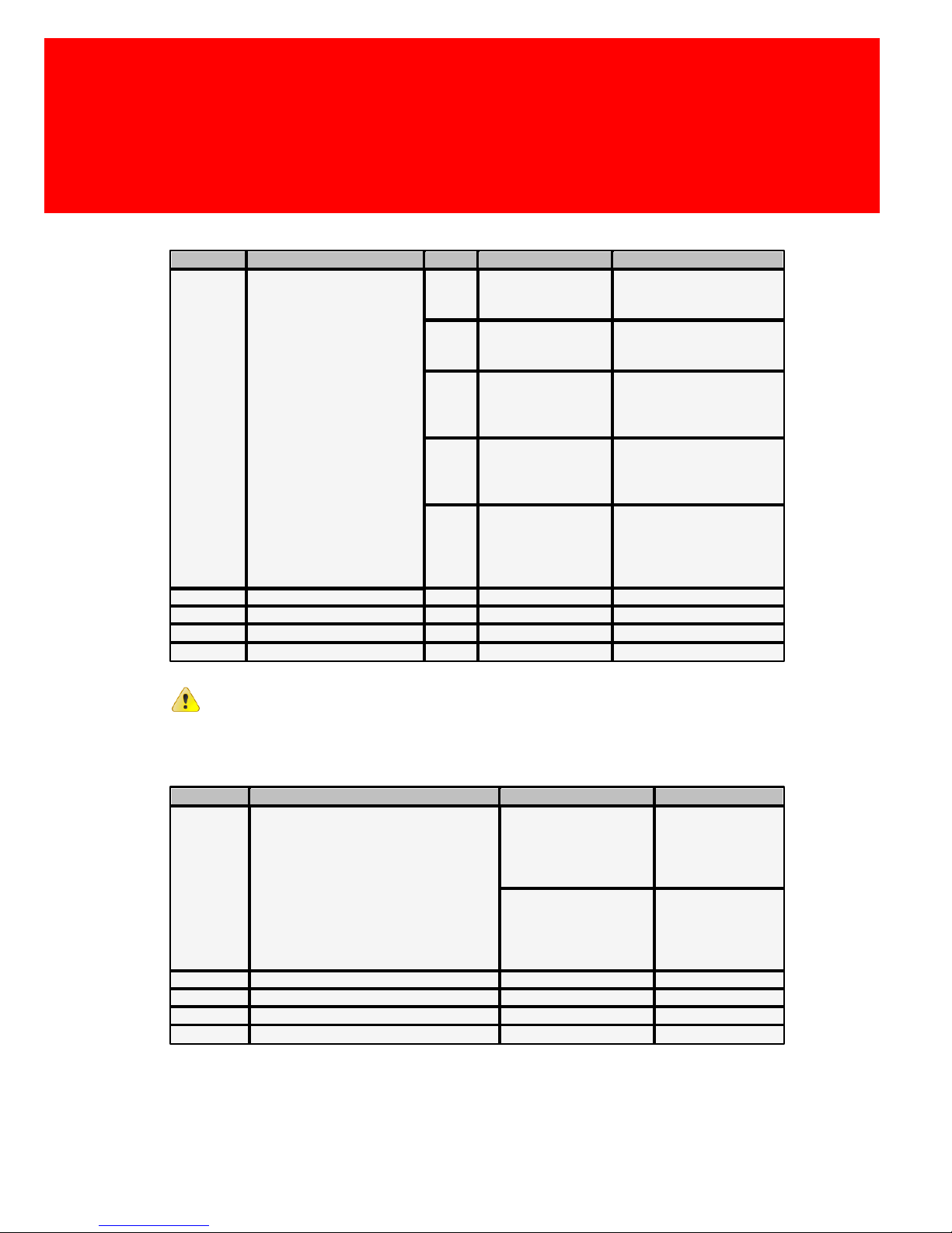
Multi tag:
Setting
Description
Value
Card Types
Behaviour
Setting 1
IP reader will read the
following protocols:
EM4x02, EM4x05,
EM4x50, hitag1, hitag2, Q5
and Ti-RFID.
Because of the emulation
of the EM4x02 card and
the EM4x05 card by the Q5
card, these different
settings of Setting 1 are
supported.
0
EM4x50, hitag1,
hitag2, Q5 and
Ti-RFID
-
1
EM4x02, EM4x05,
EM4x50, hitag1,
hitag2 and Ti-RFID
-
3
EM4x02, EM4x05,
EM4x50, hitag1,
hitag2 and Ti-RFID
The card data of the
EM4x02 cards will be
processed and send in
reversed order.
5
EM4x02, EM4x05,
EM4x50, hitag1,
hitag2 and Ti-RFID
The card data of the
EM4x05 cards will be
processed and send in
reversed order.
7
EM4x02, EM4x05,
EM4x50, hitag1,
hitag2 and Ti-RFID
The card data of the
EM4x02 and EM4x05
cards will be processed
and send in reversed
order.
Setting 2
Not applicable
---
Setting 3
Not applicable
---
Data 1
Not applicable
---
Data 2
Not applicable
---
Warning: Processing and sending of data in reversed order not
tested for the EM4x05 cards.
Mifare:
Setting
Description
Value
Card Types
Setting 1
The Mifare reader supports the 4 bytes
Mifare card serial number and 7 bytes
Desfire card serial number.
Setting 1 will be used to determine if
the order of the 4 bytes Mifare card
serial number should be reversed.
Only 4 bytes of the Desfire card serial
number are used to calculate the
decimal card number.
0
Card serial number
is calculated from
the raw data in the
reversed order.
1
Card serial number
is calculated from
the raw data in the
normal order.
Setting 2
Not applicable
--Setting 3
Not applicable
--Data 1
Not applicable
--Data 2
Not applicable
-
-
Page 38
30 - Inepro IP Reader V2
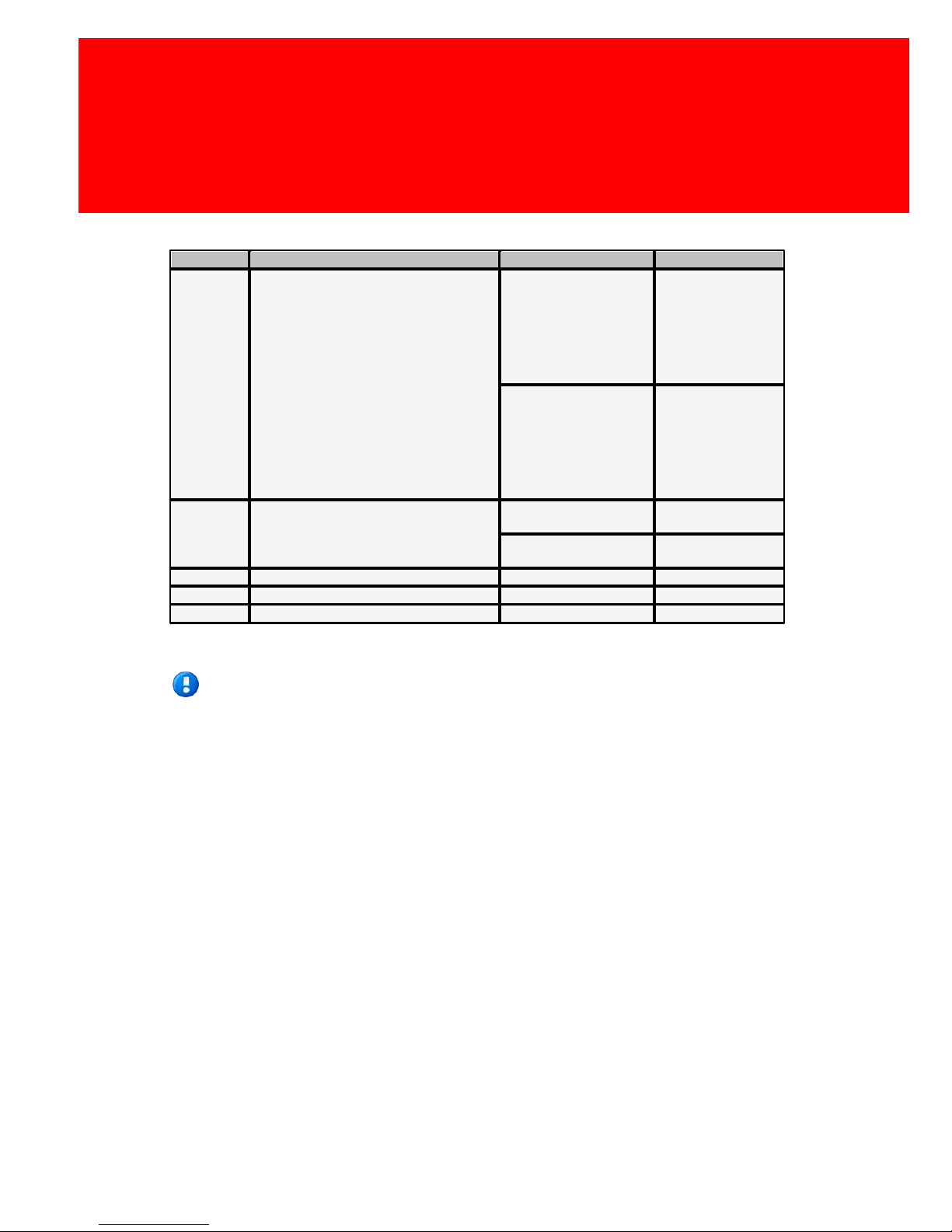
Legic:
Setting
Description
Value
Card Types
Setting 1
The IP reader supports:
Legic Prime
Legic Advant
Mifare (classic)
Mifare Desfire
ISO 15695
Setting 1 will be used to determine if
the order of the card serial number
should be reversed for the Mifare
Classic
For ISO 15695 and Mifare Desfire are
not influenced by these settings
0
Card serial number
is calculated from
the raw data in the
reversed order.
1
Card serial number
is calculated from
the raw data in the
normal order.
Setting 2
Legic Prime Read Setting
0
Standard Legic
Prime number
1
Reversed Legic
Prime number
Setting 3
Not applicable
--Data 1
Not applicable
--Data 2
Not applicable
-
-
Note: When you can't find your card reader type in these
tables, please contact Inepro for the settings for your reader. They
will send you the latest version of this manual.
Page 39

VIII
Specifications
Part
Page 40
32 - Inepro IP Reader V2
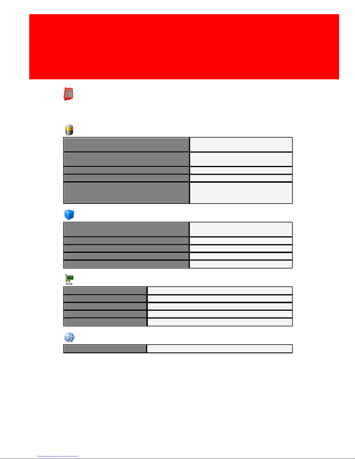
Specifications
Power
Power Supply (via adapter)
Switch regulated, high efficiency
12V DC adapter 1VA
Power Supply (via PoE)
Confirm IEEE 802.3 AF
specifications
Operation Voltage Range DC (via adapter)
10 to 20V DC
Operation Voltage Range DC (via PoE)
40 to 60V DC
Power Consumption
At maximum (depending on
hardware configuration, like card
reader) 3 VA
Housing
Material
PC / ABS crash-, flame-, and
scratch-resistant plastic
Colour Antenna Board Housing
Red
Colour Controller Board Housing
Light Grey
Dimensions Controller Board Housing
11,5 x 16 x 3,4 (W x H x D)
Dimensions Antenna Board Housing
7,9 x 7,5 x 12,1 (W x H x D)
Local Area Network (LAN)
Connector (Both)
RJ-45
Network Interface (Both)
Confirm IEEE 802.3, 100Base-T
Transmission Speed (Both)
100 Mbps
Power over Internet (PoE)
Confirm IEEE 802.3 AF
IP-Address
DHCP client or static IP
Environmental conditions
Operating Requirements
Suitable for indoor use only
Page 41

Specifications
Version 2.1.1 - 33
<This page is blank intentionally>
Page 42

34 - Inepro IP Reader V2
<This page is blank intentionally>
Page 43

Specifications
Version 2.1.1 - 35
<This page is blank intentionally>
Page 44

Page 45

IX
Appendix I
Part
Page 46
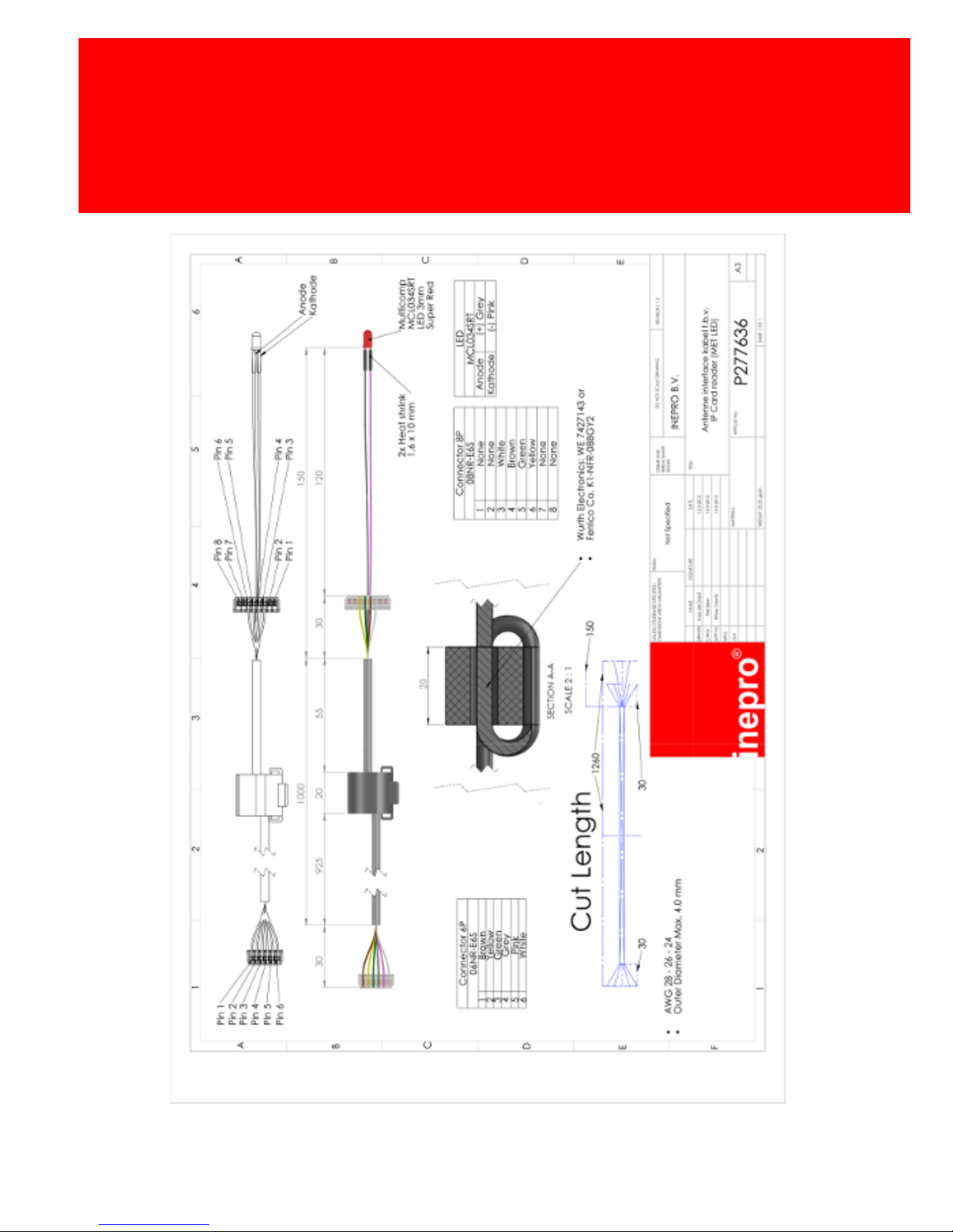
38 - Inepro IP Reader V2
Page 47

 Loading...