

We,
Inepro Metering BV
(supplier’s name)
Pondweg 7
2153 PK Nieuw-Vennep
The Netherlands
(supplier’s address)
declare under our sole responsibility that the product:
PRO2-S
PRO2-2T
PRO2-Mb
PRO2-Mod
Single phase DIN rail Watt Hour meter
(Name, type or model, batch or serial number, possibly source and number of items)
to which this declaration relates in conformity with the following European
harmonized and published standards at date of this declaration:
EN 50470
(Title and or number and date of issue of the applied standard(s))
Following the provisions of the Directives (if applicable):
N/A
Nieuw-Vennep, 2017, May 5
Place and date of issue
D. van der Vaart
Name of responsible for CE-marking
This declaration of
Conformity is suitable
to the European
Standard EN 45014
General Criteria for
Supplier’s Declaration
of Conformity. The
basis for the criteria
has been found in
international
documentation,
particularly in
ISO / IEC, Guide 22,
1982, Information on
manufacturer’s
Declaration of
Conformity with
standards or other
technical
specifications
Caution
• Turn o and if possible lock all sources supplying the
energy meter and the equipment that is connected to it
before working on it.
• Always use a properly rated voltage sensing device to
conrm that power is o.
• The connecting wire, connecting the device to the
outside circuit, should be sized in accordance with local
regulations for the maximum amount of the current
breaker or other overcurrent protection devices used in
the circuit.
• An external switch or a circuit-breaker should be
installed on the supply wires, which will be used to
disconnect the meter and the device supplying energy.
It is recommended that this switch or circuit-breaker is
placed near the meter because that is more convenient
for the operator. The switch or circuit-breaker should
comply with the specications of the building’s electrical
design and all local regulations.
• An external fuse or thermal cut-o used as an
overcurrent protection device for the meter must be
installed on the supply side wires. It’s recommended
that this protection device is also placed near the meter
for the convenience of the operator. The overcurrent
protection device should comply with the specications
of the building’s electrical design and all local regula-
tions.
• The installation should be performed by qualied
personnel familiar with applicable codes and
regulations.
• Use insulated tools to install the device. A fuse, thermal
cut-o or single-pole circuit breaker should be tted on
the supply line and not on the neutral line.
• This meter can be installed indoor, or outdoor
enclosed in a meter box which is suciently protected,
in accordance with local codes and regulations.
• To prevent tampering, an enclosure with a lock or a
similar device can be used.
• The meter has to be installed against a re resistant
wall.
• The meter has to be installed in a well-ventilated and
dry place.
• The meter has to be installed in a protective box if the
meter is exposed to dust or other contaminants.
• The meter can be installed and used after being tested
and can be sealed afterwards.
• The device can be installed on a 35mm DIN rail.
• The meter should be installed on a location where the
meter can be read easily.
• In case the meter is installed in an area with frequent
surges for example due to thunderstorms, welding
machines, inverters etc., the meter is required to be
protected with a Surge Protection Device.
• The device should be sealed immediately after
Warning
installing it in order to prevent tampering.
• The device should be installed with a torque screw
driver.
This short user manual does not contain every applicable safety regulation for using this meter. Also it might be required
because of company, local governement regulations or (inter)national laws to take additional measures. We have checked
the contents of this manual and every eort has been made to ensure that the descriptions are as accurate as possible.
However, deviations from the description cannot be completely ruled out, so that no liability can be accepted for any errors
or omissions in the information given. Versions might be dierent in default programming based on the customers order.
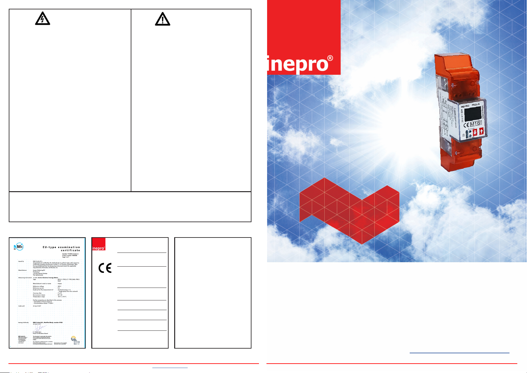
Certicates
PRO2-S
PRO2-2T
PRO2-Mb
PRO2-Mod
PRO2 series MID
Single phase energy meter
Declaration of Conformity
We
Inepro Metering BV
Inepro Metering B.V. - Pondweg 7 - 2153 PK Nieuw Vennep - The Netherlands - T: +31(0)252 744044 - www.ineprometering.com Inepro Metering B.V. - PRO2 short user manual - Version 2.18 - 05.05.2017 - Subject to change without notice
and satisfy the appropriate requirements of the Directive 2014/32/EU
Of
Inepro Metering BV
Pondweg 7
2153 PK Nieuw Vennep
The Netherlands
Ensure and declare that the apparatus:
PRO2-S , PRO2-2T , PRO2-Mb and PRO2-Mod
With the measurement range
230V, 5(100)A, 50Hz, 10.000imp/kWh
are in conformity with the type as described in the
EC-type examination certificate T11019
May 5, 2017
Daan van der Vaart
Short user manual
Version 2.18
Please note that this document is only a short user manual and does not handle every
function. The complete user manual is available at: www.ineprometering.com/download.

Specications
Display pages
Nominal voltage (Un) 230V AC
Operational voltage 195-253VAC
Insulation capabilities:
- AC voltage withstand 4KV for 1 minute
- Impulse voltage withstand 6KV - 1,2 µS waveform
Base current (Ib) 5A
Maximum rated current (Imax) 100A
Operational current range 0,4%Ib-Imax
Overcurrent withstand 30Imax for 0,01s
Operational frequency range 50Hz ±10%
Internal power comsumption ≤2W/Phase - ≤10VA/Phase
Test output ash rate (RED LED) 10.000 imp/kWh
Pulse output rate 10.000/2.000/1.000/100/10/1/0,1/0,01 imp/kWh
Pulse width:
- 1.000/100/10/1/0,1/0,01 imp/kWh 31ms
- 2.000 imp/kWh < 30kW 31ms
- 2.000 imp/kWh > 30kW 15ms
- 10.000 imp/kWh < 6kW 31ms
- 10.000 imp/kWh > 6kW 15ms
- 10.000 imp/kWh > 12kW 5ms
Operating temperature -40°C - +70°C
Accuracy class B (=1% accuracy)
Data store The data can be stored for more than 10 years without power
Default settings
LCD cycle time 10s Automatic scroll Total active energy, Active power
Backlight Button Baud rate 9600
S0 output 1.000 Parity Even
Combination code C01 (forward only) Password 0000
Modbus/M-bus ID 01/00 OBIS codes OFF
Dimensions
Height without protection cover 92,5 mm
Height 141,5 mm
Width 35,8 mm
Depth 63 mm
Max. diameter power connection clamps 35mm
2
Weight 0,16 Kg (net)
NOTE: The housing is sealed, do not open the meter!
No warranty if the housing is opened or the seal is
removed.
Connection diagram
1 Phase line in (L-IN)
3 Phase line out (L-OUT)
4 Neutral line in (N)
6 Neutral line out (N)
10 & 11 Modbus/M-bus communication contact
12 & 13 External tari input (PRO2-2T version only)
18 & 19 Pulse output contact (S0) forward
20 & 21 Pulse output contact (S0) reverse
Automatic scroll: default 10 seconds
Total active energy
Active power
PRO2-2T, PRO2-MB & PRO2-MOD
PRO2-MB & PRO2-MOD
Button scroll: press the buttons for less than 3 seconds to scroll. After 30 seconds of no interaction the meter goes back to automatic scroll mode.
Total active
energy
Total reactive
energy
Active power Voltage Current Frequency Active power Reactive power Apparent power Power factor
Resettable kWh Resettable kWh
Program mode 1
(Read only)
Program mode 2
(Write)
Program mode 3
(Write: password
protected)
Total active
energy
Program verify sum Meter serial number
Total reactive
energy
Hold
the
right
button
for 3
seconds
to
enter
the
next
menu.
Hold
the
left
button
for 3
seconds
to go
back.
Display
LCD cycle time Backlight S0 output Combination
Shows:
>>
or
Power down counter
<<
LCD cycle time Backlight Modbus/M-bus ID
Scroll with the
buttons to select
1-30.
Hold both buttons
for 3 seconds
to conrm.
S0 output Combination
Hold
the
right
button
for 3
seconds
Scroll with the
and
buttons to select
10.000/2.000/
enter 4
1.000/100/10/
digit
1/0,1/0,01.
password
Hold both buttons
to
for 3 seconds
enter
to conrm.
program
mode.
Total forward
active energy
Total forward
reactive energy
Hold the right button
for 5 seconds to reset.
Scroll with the
buttons to select
on/o/button.
Hold both buttons
for 3 seconds
to conrm.
code
Scroll with the
buttons to select
01(F)/04(R)/
05(F+R)/06(R-F)/
09(F-R)/10(F-R).
Hold both buttons
for 3 seconds
to conrm.
Total reverse
active energy
Total reverse
reactive energy
Scroll with the
buttons to select
3 digits.
Conrm each digit
by holding both
buttons for 3 seconds.
Baud rate Parity Power down
Scroll with the
buttons to select
300/600/1200/
4800/9600.
Hold both buttons
for 3 seconds
to conrm.
T1 forward
active energy
T1 forward
reactive energy
code
Scroll with the
buttons to select
even/none/odd.
Hold both buttons
for 3 seconds
to conrm.
T1 reverse
active energy
T1 reverse
reactive energy
Modbus/M-bus IDBaud rate Resettable kWh Parity
counter
Hold both buttons
for 3 seconds
to reset.
T2 forward
active energy
T2 forward
reactive energy
Password OBIS codes
Select the new
4 digit password
by choosing each
digit (0-9).
Conrm each
digit by holding
both buttons for
3 seconds
T2 reverse
active energy
T2 reverse
reactive energy
Select
ON or OFF.
Hold both buttons
for 3 seconds
to conrm.
PRO2-MOD
Hold
the
right
button
for ≥5
seconds
to add
or
remove
from
the
automatic
scroll.
Display
Shows:
OK IN
or
OK OUT
Hold
the
right
button
for ≥5
seconds
to
enter
program
mode.
 Loading...