

Page 1
02VJ-004 rev.2
RF Pilot
Wireless remote controller with display
EN
Perenmarkt 10B, 1681PG ZWAAGDIJK-OOST ind.terrein: WFO/ABC THE NETHERLANDS
Tel: +31(0)228-567729, Fax: +31(0)228-567797, Email: info @ wardenaar.com, Internet: www.wardenaar.com
Rabobank 32 69 98 268, KvK te Alkmaar 37079598, BTW NL 8070.48.768.B01
1/8
The User’s Manual provides in formation for the installation and use of the device. Th e Manual is always included in th e package. The
device may only be installed and connected by per sons with re quisite professional qualif ications who have become thoroughl y
familiarize d with this Manu al and the fun ctions of the device. Trouble -free operation also depends on the previous met hod
of transpor tation, storage and handling. Should you become aware of any sig ns of damage, deformation, malfunction or of any
missing par ts, do not ins tall this product and return it to the vend or. After the e xpiry of its ser vice life, the product and all its par ts
must be disposed of as electronic waste. With consideration to the transmission of the RF signal, ensure that RF components are
suitably located in the building where the dev ice is to be installed. The RF Control system must onl y be installed in indoor areas . The
device has not b een designed for outdo or use or use in mo ist environme nt, it must not b e installe d in metal dist ribution b oxes and
plastic distribution boxes with metal doors as this would prevent t he transmission of the radio frequenc y signal. RF Co ntrol is not
recommende d for the contro l of devices providing for vi tal life fun ctions or for the control of r isk devices such as lifts , pulleys etc. radio fre quency transmissi on could be hampere d with an obstacle, inter fered with, the t ransmitter bat tery may become de pleted etc.
thus disablin g the remote control. Not suitabl e for use in industrial environm ent.
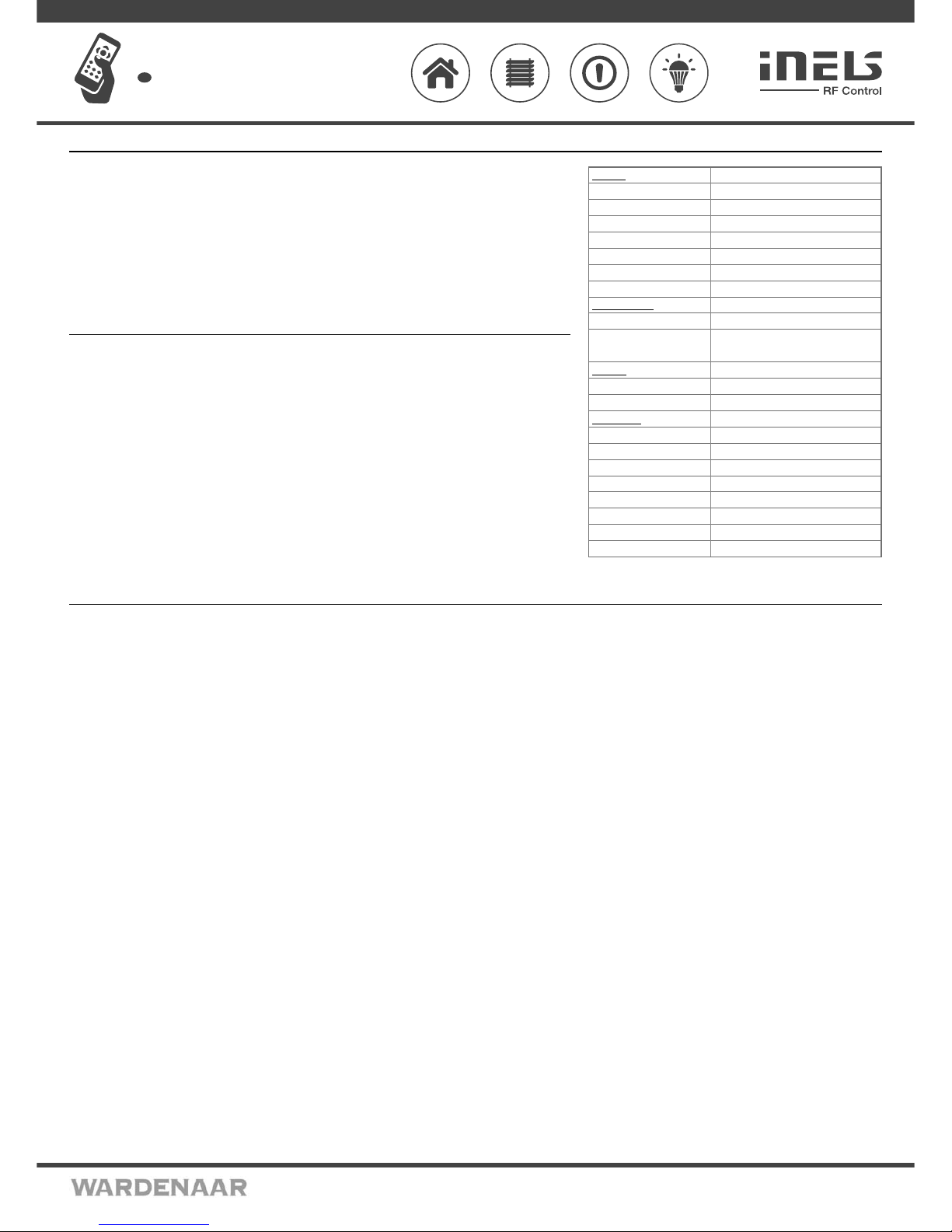
Before You Start...
Display
Type:
Resolution:
Side ratio:
Visible surface:
Backlighting:
Diagonal:
Control:
Power supply
Power supply:
Battery life:
Control
Range in free space:
Frequency:
Other data
Operating temperature:
Storage temperature:
Color design:
Protection:
Operating position:
Dimensions:
Weight:
Related standards:
Technical parameters
color OLED
128 x 128 pixels
1:1
26 x 26 mm
self-illuminating text
1.5“
direction button, control buttons
2 x 1.5 V AAA batteries / R03*
approx. 3 years, according to the
frequency of use and battery type
up to 200 m
866 MHz, 868 MHz, 916 MHz, 922 MHz
0 to +55 °C
-20 to +70 °C
white anthracite
IP20
any
130 x 41 x 18 mm
61 g
EN 60730-1
• The RF Pilot remote control is a central controller for switching elec trical appliances and equipment, dimming lights, con trolling blinds, etc.
• When pressing the button, it sends a set signal (ON / OFF, dimming, time switching OFF / ON, blinds up / down).
• Option of set ting light scenes, where with a single press, you can control up to 10 units at once.
• The Favorites mode lets you preset the most frequently used devices on the home screen.
• Option of grouping dimmers (RFDA-73M/RGB), where you can place up to 10 units under a single control panel = control
of over 100 m of colored LED strip.
• Designed in white and anthracite with color OLED display.
• Display of room temperature, battery status, date and time direc tly on display.
• Bidirectional communication, transmits and receives commands and displays the status of unit s.
• Thanks to the function of measuring the signal between the controller and unit, you can use it for testing the range and
signal quality.
• It is possible to combine up to 40 unit s of iNELS RF Control (you can gradually expand the installation from 1 unit).
• Battery power (1.5 V 2x AAA - included in supply) with batter y life of around 3 years based on frequency of use and type
of batteries.
• Range up to 200 m (in op en space), if the signal is insufficient between the controller and unit, use the signal repeater
RFRP-20.
• Communication frequenc y with bidirectional protocol iNELS RF Control.
Characteristic
Overview of wireless RF Control devices
Controllers
RFWB-20/G, RFWB-40/G
- Wireless wall controller - 2 button / 4 button
RF Key - 4 button co ntrolle r, keychain
RF Pilot - Wire less remote controller with display
RFSG-1M - Wireless contac t conver ter - 2 inputs
RFIM-20B, RFIM-40B - Wireless contact conver ter (2 inputs / 4 inputs)
System units
RF Touch-B, RF Touch-W
- Wireless touch unit - fl ush / sur face mounted
eLAN-RF-003 - Smart RF box
eLAN-RF-Wi-003 - Smart RF box with Wi- Fi
RFRP-20 - Repeater to exten d the range
RFGSM-220M - Energy gateway
Switches
RFSA-11B
- Wireless switch unit (single-f unction) - 1 output
RFSA-61B - Wireless switch unit (multi-function) - 1 output
RFSA-62B - Wireless switch unit (fl ush mounted) - 2 outputs
RFSAI-61B - Wireless switch unit with the input (for a pushbutton)
RFSA-61M - Wireless switch unit - 1 output
RFSA-66M - Wireless switch unit - 6 outputs
RFSC-61 - Switching socket (multi-function)
RFUS-61 - Switch unit for outdoor use (multi-function)
RFJA-12B, RFJA-32B - Switch unit for sh utters
Dimmers
RFDA-73M/RGB
- Dimming actuator
RFDEL-71B - Universal dimmer (fl ush mounted)
RFDEL-71M - Universal dimmer (DIN rail mounted)
RFDW-71 - Wireless Dimmer Switch
RFDSC-71 - Dimming socket (multi-function)
RFDAC-71B - Analog controller 0(1)-10V
Lighting
RFSOU-1
- Wireless twilight switch
RF-RGB-LED-550 - Wireless coloured bulb
RF-White-LED-675 - Wireless white bulb
Temperature control
RFATV-1
- Wireless thermo-valve
RFSTI-11B - Switch unit with a temperature sensor (fl ush mounted)
RFSTI-11/G - Switch unit with a temperature sensor
RFTI-10B - Wireless temperature sensor
RFTC-10/G - Simple wireless temperature controller
RFTC-50/G, RFTC-100/G - Wireless temp erature controllers
Energy management
RFPM-2M
- Energy gateway
RFTM-1 - Wireless pulse converter
Monitoring units
RFSF-1B
- Wireless fl ood detector
RFSD-100, RFSD-101 - Smoke detector wireless
RFMD-100 - Motion detector wireless
RFWD-100 - Window / Door detector wireless
Accessories
FP-1
- Flood probe
TC, TZ, Pt100 - Temperature sensors
AN-I - Intern al antenna
AN-E - External antenn a
Telv a - Thermodrive
CT50 - Current transformer
LS, MS, WS, IRS - LED sensor, Magnetic sensor, Infra Re d senso r
* batteries are included in th e package
Page 2
02VJ-004 rev.2
RF Pilot
Wireless remote controller with display
EN
Perenmarkt 10B, 1681PG ZWAAGDIJK-OOST ind.terrein: WFO/ABC THE NETHERLANDS
Tel: +31(0)228-567729, Fax: +31(0)228-567797, Email: info @ wardenaar.com, Internet: www.wardenaar.com
Rabobank 32 69 98 268, KvK te Alkmaar 37079598, BTW NL 8070.48.768.B01
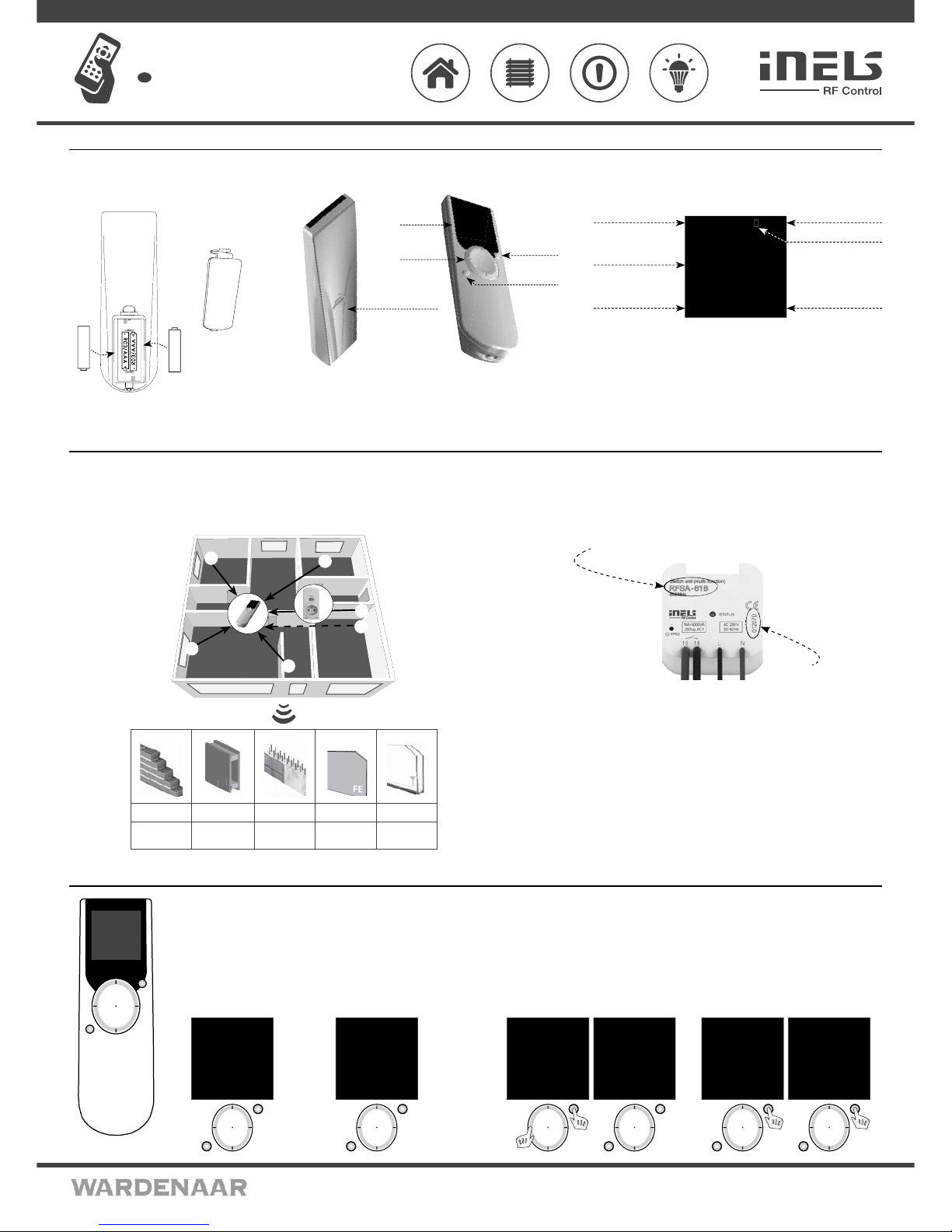
Battery insertion Device description Display description - basic display
+
+
-
Display
Direction
button
Control
button T1
Control
button T2
TimeDate
Current temperature
display
Enter the menu
Quick Control
options
Battery
cover
Low battery
indicator
Remove the battery cover and insert two R03/
AAA batteries as indicated.
Battery
cover
Device
mo 01.01.10 12:54
Favourite 1
Favourite 2
Favourite 3
Favourite 4
Favourite 5
Favourite 6
Favourite 7
Temp.: 23C MENU
The memory has an independent power supply. Any custom adjustment (except for time and date) will remain.
After inserting the batteries, the RF Pilot name and the fi rmware number will appear on the initial screen.
Radio frequency signal penetration through various construction materials
Basic Steps for Successful Programming of RF Pilot
Step 1 - Locati on of RF units
Keep in mind that the radio signal range for RF installations depends on the building struc ture, materials
used and the manner of unit location in the area.
Step 2 - Complete t he Installation Form
- name of the device you want to control
- names of units (e.g.: RFSA-61B, ...)
- addresses of units (e.g.: 577515, ...)
(The Installation Form is included at the end of the Manual).
Name
Address
E.g.: RFSA-61B
E.g.: 577515
Step 3 - Add actu ator
Add actuators and their addresses into the Contro ller memory.
Step 4 - Alloca tion of actuators to ro oms
Allocation of actuators to rooms.
Step 5 - Option al setting
Rename actuator according to your requirements. Test of the range and RF signal
quality. Rename Room. Create Scene. Saving most frequently used Actuators / Rooms
/ Scenes in the Initial Screen Favourite as shor tcuts.
☺
☺
☺
☺
☺
RFRP-20
60 - 90 %
80 - 95 %
20 - 60 %
0 - 10 % 80- 90 %
brick walls
wooden structures
with plaster boards
reinforced
concrete
metal partitions
common
glass
Controller Activation Settings Menu / Settings - Language
T1
T2
Fig. 3
mo 01.01.10 12:54
Rooms
Scenes
Favourite
EXIT SELECT
T1
T2
Fig. 2
mo 01.01.10 12:54
Favourite 1
Favourite 2
Favourite 3
Favourite 4
Favourite 5
Favourite 6
Favourite 7
Temp.: 23C MENU
Fig. 1
As standard, the display is in the sleep mode - no information is displayed
(Fig. 1).
Press any button briefl y to display the Initial Screen (Fig. 2).
Press T1 to enter the Basic Menu (Fig. 3).
Note: When using the controller, 10 seconds after pressing any button, the RF Pilot switches
to the sleep mode. In the Settings Menu, it switches to the sleep mode 40 seconds after
pressing any button.
Settings Menu
To enter the Settings Menu (Fig. 5), press the left side of the direction button together with the T1
button (Fig. 4) in the Basic Menu.
T1
mo 01.01.10 12:54
Rooms
Scenes
Favourite
EXIT SELECT
Fig. 4
T1
T2
Language
Date and time
Actuators
Rooms
Scenes
Favourite
Device reset
EXIT SELECT
Fig. 5
T2
T1
Cestina
Slovencina
English
Deutsch
Magyar
Pyccии яз.
Romana
Polski
EXIT SELECT
Fig. 7
T2
T1
Language
Date and time
Actuators
Rooms
Scenes
Favourite
Device reset
EXIT SELECT
Fig. 6
Language
Used for language setting. Press T1 (Fig. 6) to enter the Language Menu. Choose the requested
language using the direction button (Fig. 7). Confirm using the T1 button.
2/8
Page 3
02VJ-004 rev.2
RF Pilot
Wireless remote controller with display
EN
Perenmarkt 10B, 1681PG ZWAAGDIJK-OOST ind.terrein: WFO/ABC THE NETHERLANDS
Tel: +31(0)228-567729, Fax: +31(0)228-567797, Email: info @ wardenaar.com, Internet: www.wardenaar.com
Rabobank 32 69 98 268, KvK te Alkmaar 37079598, BTW NL 8070.48.768.B01
Settings - Date and time
Move in the Settings menu using the direction button to sele ct Date and time. Confirm using the T1 button
(Fig. 1).
Here you can set the current time, time format (12/24), date and day of the week (Fig. 2).
- You can move in the requested direction by pressing the upper or lower part of the direction button.
- You can display a wider selection of settings by pressing the right or left side of the direction button.
- Set the value by pressing the sides of the direction button (Fig. 3).
- Save the settings by pressing T1.
T1
T2
mo 01.01.10 12:54
Hours:
00
Minutes:
00
EXIT SAVE
Fig. 3
T1
T2
Time:
00:00
Format :
12
Date:
01.01.2010
Day in week:
Monday
EXIT SAVE
Fig. 2
T1
T2
Language
Date and time
Actuators
Rooms
Scenes
Favourite
Device reset
EXIT SELECT
Fig. 1
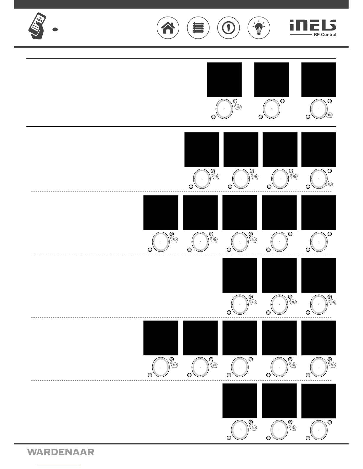
Move in the Settings Menu using the direction button to select Actuators. Press the T1 button to
display the Settings Menu (Fig. 1, 2).
Add - adding actuators to the RF Pilot Controller (Fig.2).
Use the direction button to select the actuator type which you want to use. Confirm using the T1
button (Fig. 3).
In the following menu, enter the actuator address using the direction button (Fig. 4).
Note.: - Move in the address line by pressing the direction button in the left or right direction.
- Select characters by pressing the direction button - up and down.
Confirm using the T1 button.
T1
T2
Language
Date and time
Actuators
Rooms
Scenes
Favourite
Device reset
EXIT SELECT
Fig. 1
T1
T2
mo 01.01.10 12:54
Type:
RFSA-11B
RFSA-6xM
RFJA-12B
RFDA-71B
RFDA-11B
RFDAC-71B
EXIT SELECT
Fig. 3
T1
T2
mo 01.01.10 12:54
Address:
000000
0 1 2 3 4 5 6 7 8 9
A B C D E F
EXIT SAVE
Fig. 4
T1
T2
mo 01.01.10 12:54
Add
Assign
Rename
Range test
Control
Remove
EXIT SELECT
Fig. 2
Settings - Actuators
Assign - used to assign the added ac tuator to a room (Fig.1). Names of
Rooms 1-10 are set as default in the Controller.
Using the direc tion button selec t the actuator to be assigned. Confirm
selection using the T1 but ton (Fig. 2). After entering the nex t menu,
using the direction button select the name of the room you want to
assign the actuator to. Confirm using the T1 button (Fig. 3). Actuator is
assigned (Fig. 4).
Note: If the name h as already been assign ed, a warning is displaye d, see Fig. 5.
T1
T2
mo 01.01.10 12:54
Add
Assign
Rename
Range test
Control
Remove
EXIT SELECT
Fig. 1
T1
T2
Memory:
1/40
Type/address:
RFSA11/012345
Room:
Not allocated
Name:
Actuator 1
EXIT ASSIGN
Fig. 2
T1
T2
mo 01.01.10 12:54
Room
assigned
EXIT ASSIGN
Fig. 4
T1
T2
Actuator
already used !
Fig. 5
T1
T2
mo 01.01.10 12:54
Room 1
Room 2
Room 3
Room 4
Room 5
Room 6
Room 7
EXIT ASSIGN
Fig. 3
Rename - (Fig. 1) used to name the actuato r, the name will be disp layed in the main menu list. The Co ntroller automatically
arranges the names of Actuator 1 - 40 in order in th e Add Menu. (The Rename function is optional.)
Using the direc tion button selec t the actuator to be renamed . Confirm using the T1 button (Fig. 2). Cho ose the name of the
actuator using the direction button in the following list.
Confirm using the T1 button (Fig. 3).
Note.: - Move in the a ctuator name line by pressin g the direction but ton in the left or right pa rt.
- Select ch aracter s by pressing the directio n button - up and down (max. 12 charac ters). Press the T2 bu tton to dele te the
marked character.
T1
T2
mo 01.01.10 12:54
Add
Assign
Rename
Range test
Control
Remove
EXIT SELECT
Fig. 1
T1
T2
Memory:
1/40
Type/address:
RFSA11/012345
Room:
Room 1
Name:
Actuator 1
EXIT RENAME
Fig. 2
T1
T2
Name:
Lamp
_ A B C D E F G H I J
K L M N O P Q R S T U
V W X Y Z a b c d e f
g h i j k l m n o p q
r s t u v w x y z
0 1 2 3 4 5 6 7 8 9
DELETE SAVE
Fig. 3
Range test - used to determine the quality of the signal between the
RF Pilot and the controlled actuator (Fig. 1). Use the direction button to
select th e actuator the signal of which you want to test. Confirm using
the T1 button (Fig. 2). The test result will be displayed after approx. 10s
(Fig. 3). Reach Test is an optional function.
Control - Control - serves for a quick test of ac tuator func tion (Fig. 4).
Using the direc tion button selec t the actuator to be contro lled. Confirm
using the T1 button (Fig. 5). The list of functions supported by the selected ac tuator will be displayed.
T1
T2
Memory:
2/40
Type/address:
RFSA6x/123456
Room:
Room 1
Name:
Lamps
EXIT SELECT
Fig. 5
T1
T2
mo 01.01.10 12:54
Add
Assign
Rename
Range test
Control
Remove
EXIT SELECT
Fig. 4
T1
T2
mo 01.01.10 12:54
Actuator test:
Paket: 0/10
Signal status 0%
CONTINUE
Fig. 3
T1
T2
Memory:
1/40
Type/address:
RFSA11/012345
Room:
Room 1
Name:
Lamps
EXIT SELECT
Fig. 2
T1
T2
mo 01.01.10 12:54
Add
Assign
Rename
Range test
Control
Remove
EXIT SELECT
Fig. 1
Remove - used to delete the actuator from the memory of RF Pilot (Fig. 1).
Using the direction button select the actuator to be removed.
Confirm using the T1 button (Fig. 2).
Note: If an actuator is removed from the controller memory, the relevant position in the actuator list becomes vacant (Fig. 3).
The first vacant position in the list is used to assign the next actuator.
T1
T2
mo 01.01.10 12:54
Add
Assign
Rename
Range test
Control
Remove
EXIT SELECT
Fig. 1
T1
T2
Memory:
3/40
Type/address:
RFSA11/012345
Room:
Not allocated
Name:
Actuator 1
EXIT DELETE
Fig. 2
T1
T2
Memory:
3/40
Type/address:
Free position
Room:
Free position
Name:
Free position
EXIT
Fig. 3
3/8
Page 4
02VJ-004 rev.2
RF Pilot
Wireless remote controller with display
EN
Perenmarkt 10B, 1681PG ZWAAGDIJK-OOST ind.terrein: WFO/ABC THE NETHERLANDS
Tel: +31(0)228-567729, Fax: +31(0)228-567797, Email: info @ wardenaar.com, Internet: www.wardenaar.com
Rabobank 32 69 98 268, KvK te Alkmaar 37079598, BTW NL 8070.48.768.B01
Settings - Rooms
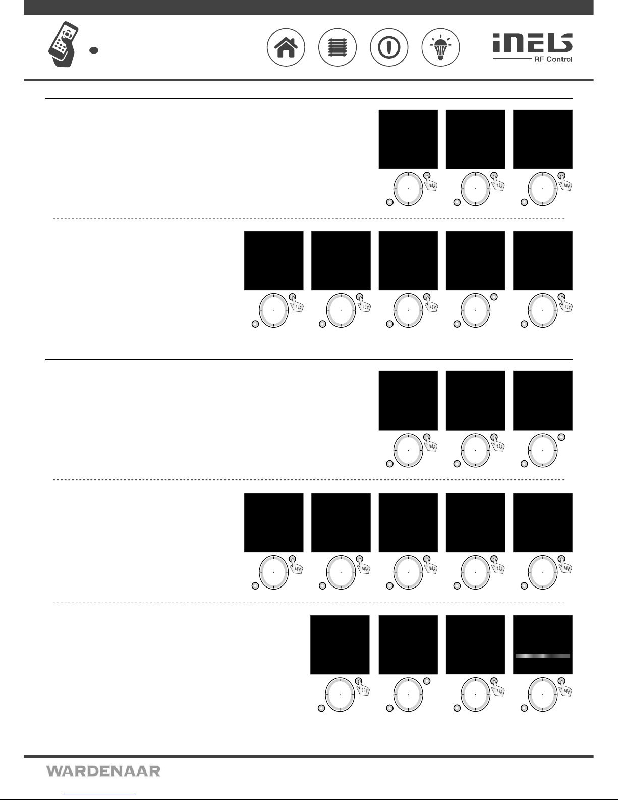
Menu Rooms is u sed to na me t he ro oms , th e nam e wi ll b e dis pla yed i n th e mai n me nu li st. Mov e in t he S ett ings Men u usi ng
the direction button to select Rooms. Press T1 to enter the menu (Fig. 1).
By pressing the direction bu tton select the Room and confirm by pressing T1 (Fig. 2). The menu is
displayed (Fig. 3): Rename, Reset.
T1
T2
Language
Date and time
Actuators
Rooms
Scenes
Favourite
Device reset
EXIT SELECT
Fig. 1
T1
T2
mo 01.01.10 12:54
Room 1
Room 2
Room 3
Room 4
Room 5
Room 6
Room 7
EXIT SELECT
Fig. 2
T1
T2
mo 01.01.10 12:54
Name:
Room 1
Rename
Reset
EXIT SELECT
Fig. 3
Rename - us ed f or n ami ng th e ro oms . ( The Ren ame f un cti on i s opt ion al. )
Using the direction button select the actuator to be renamed. Confirm
using the T1 button (Fi g. 1). Rename the scene using th e direction button
in the following menu.
Confirm using the T1 button (Fig. 2).
Note: - Move in the room name line by pre ssing the direction but ton in the
left or ri ght direction.
- Select ch aracters by pressing th e direction button - u p and down.
Reset - serves for cancelling the assignment of actuators to rooms (Fig.
3-4).
Note: The Roo m name will be reset to fac tory setting (Fig. 5).
T1
T2
mo 01.01.10 12:54
Name:
Room 1
Rename
Reset
EXIT SELECT
Fig. 1
T1
T2
Name:
Lighting
_ A B C D E F G H I J
K L M N O P Q R S T U
V W X Y Z a b c d e f
g h i j k l m n o p q
r s t u v w x y z
0 1 2 3 4 5 6 7 8 9
DELETE SAVE
Fig. 2
T1
T2
mo 01.01.10 12:54
Name:
Lighting
Rename
Reset
EXIT SELECT
Fig. 3
T1
T2
mo 01.01.10 12:54
Room
reset !
EXIT SELECT
Fig. 4
T1
T2
mo 01.01.10 12:54
Name:
Room 1
Rename
Reset
EXIT SELECT
Fig. 5
Settings - Scenes
Settings Menu - Scenes serves to set the control of multiple actuators using a single press.
Move in the Settings Menu using the direction button to select Scenes. Press T1 to enter the menu (Fig. 1).
Using the direction button select the name of the Scene. Confirm using the T1 button (Fig. 2). The following options will be
displayed (Fig. 3): Rename, Commands, Restart.
T1
T2
Language
Date and time
Actuators
Rooms
Scenes
Favourite
Device reset
EXIT SELECT
Fig. 1
T1
T2
mo 01.01.10 12:54
Scene 1
Scene 2
Scene 3
Scene 4
Scene 5
Scene 6
Scene 7
EXIT SELECT
Fig. 2
T1
T2
mo 01.01.10 12:54
Name:
Scene 1
Rename
Commands
Restart
BACK PROCEED
Fig. 3
Rename - used to name a scene, the name will be displaye d in the main
menu list. (The Rename function is optional.) Fig. 1.
Rename the scene using the direction button in the following list.
Confirm using the T1 button (Fig. 2).
Note.: - Move in the room name line by pressing the direction button in the
left or ri ght direction.
- Select ch aracters by pressing th e direction button - u p and down.
Commands - (Fig. 3) you can assign an actuator (Fig. 5) from a sele cted
room (Fig. 4) and define its function that will be executed when the
scene is activated.
Note.: Up to 10 commands can b e allocated to each scene.
T1
T2
mo 01.01.10 12:54
Name:
Scene 1
Rename
Commands
Reset
BACK PROCEED
Fig. 1
T1
T2
Name:
Kitchen
_ A B C D E F G H I J
K L M N O P Q R S T U
V W X Y Z a b c d e f
g h i j k l m n o p q
r s t u v w x y z
0 1 2 3 4 5 6 7 8 9
DELETE SAVE
Fig. 2
T1
T2
mo 01.01.10 12:54
Name:
Kitchen
Rename
Commands
Reset
BACK PROCEED
Fig. 3
T1
T2
mo 01.01.10 12:54
Lighting
Room 2
Room 3
Room 4
Room 5
Room 6
Room 7
EXIT SELECT
Fig. 4
T1
T2
mo 01.01.10 12:54
RFSA-11B
RFDA-71B
EXIT SELECT
Fig. 5
Reset - cancels the assignment of actuators to scenes (Fig. 1-2).
Note: The Scene name will be reset to factory setting (Fig. 3).
Note: If you want to control more actuators RFDA-73/RGB at the same time by one control touch panel, so
you hould choose the function “group” at each actuator, when assigning the scenes (Fig.4).
T1
T2
mo 01.01.10 12:54
Name:
Kitchen
Rename
Commands
Reset
BACK PROCEED
Fig. 1
T1
T2
mo 01.01.10 12:54
Scene
reset!
BACK PROCEED
Fig. 2
T1
T2
mo 01.01.10 12:54
Name:
Scene 1
Rename
Commands
Reset
BACK PROCEED
Fig. 3
T1
T2
mo 01.01.10 12:54
Switch On
Switch O
Brigh: 100%
White
RGB
Group
EXIT SAVE
Fig. 4
4/8
Page 5
02VJ-004 rev.2
RF Pilot
Wireless remote controller with display
EN
Perenmarkt 10B, 1681PG ZWAAGDIJK-OOST ind.terrein: WFO/ABC THE NETHERLANDS
Tel: +31(0)228-567729, Fax: +31(0)228-567797, Email: info @ wardenaar.com, Internet: www.wardenaar.com
Rabobank 32 69 98 268, KvK te Alkmaar 37079598, BTW NL 8070.48.768.B01
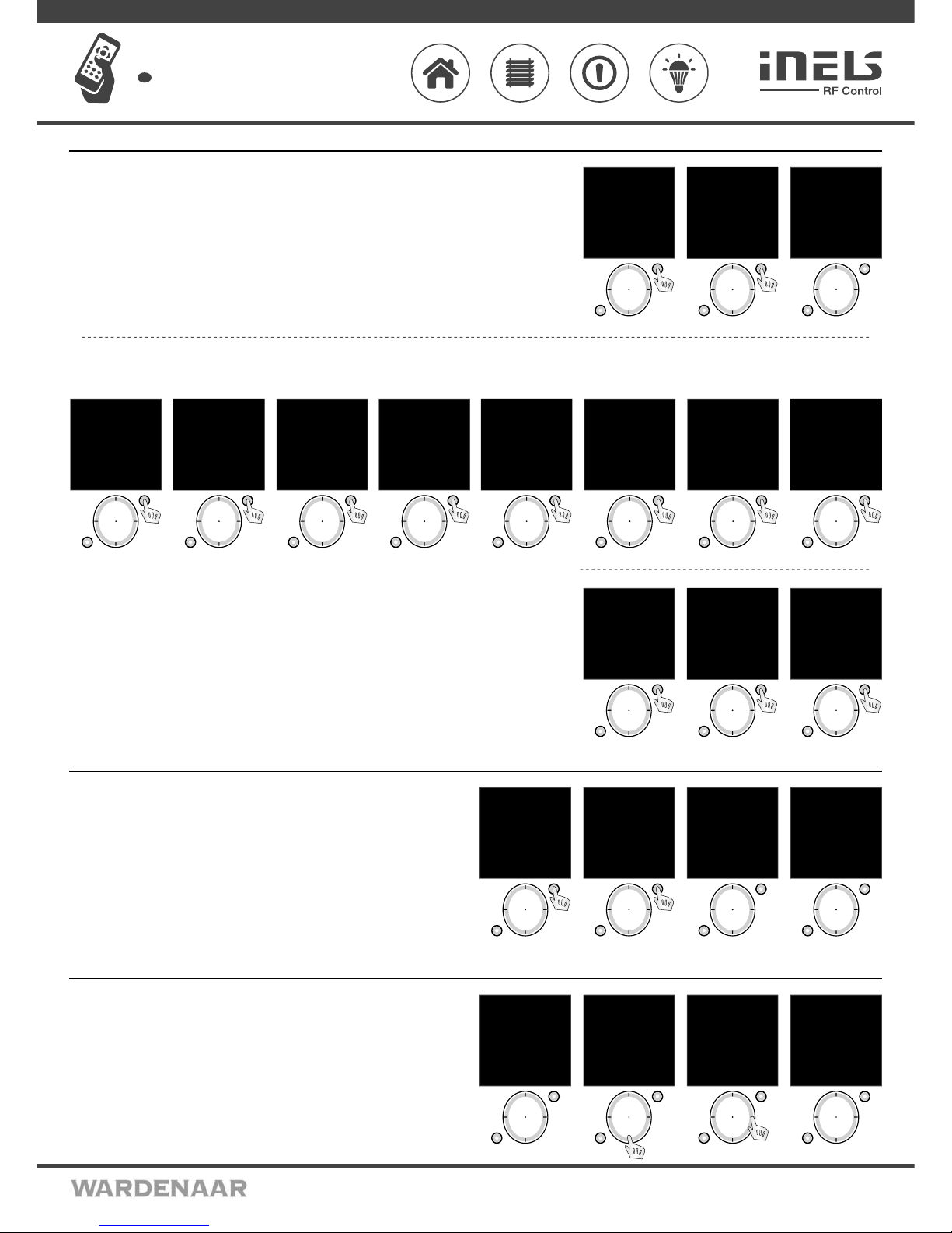
Settings - Favourite
Menu Settings - Favourite is used to include ten most frequently used devices (actuators / scenes) directly in the main
screen as a shor tcut for quick control without f urther search.
Move in the Settings Menu using the direction button to select Favourite. Press T1 to enter th e menu (Fig. 1).
In the Favourite menu sele ct the time you want to edit. Confirm using the T1 but ton (Fig. 2). The menu is displayed (Fig. 3):
Assign, Cancel.
T1
T2
mo 01.01.10 12:54
Favourite 1
Favourite 2
Favourite 3
Favourite 4
Favourite 5
Favourite 6
Favourite 7
BACK SELECT
Fig. 2
T1
T2
Language
Date and time
Actuators
Rooms
Scenes
Favourite
Device reset
EXIT SELECT
Fig. 1
;
T1
T2
mo 01.01.10 12:54
Name:
Favourite 1
Assign
Cancel
BACK SELECT
Fig. 3
T1
T2
mo 01.01.10 12:54
RFSA-11B
RFDA-71B
EXIT SELECT
Fig. 3
T1
T2
mo 01.01.10 12:54
Lighting
Room 2
Room 3
Room 4
Room 5
Room 6
Room 7
EXIT SELECT
Fig. 2
T1
T2
mo 01.01.10 12:54
Select type:
Actuator
Actuator with func.
Scene
BACK SELECT
Fig. 1
T1
T2
mo 01.01.10 12:54
Switch On
Switch O
EXIT ASSIGN
Fig. 7
T1
T2
mo 01.01.10 12:54
RFSA-11B
RFDA-71B
EXIT SELECT
Fig. 6
T1
T2
mo 01.01.10 12:54
Lighting
Room 2
Room 3
Room 4
Room 5
Room 6
Room 7
BACK SELECT
Fig. 5
T1
T2
mo 01.01.10 12:54
Select type:
Actuator
Actuator with func.
Scene
BACK SELECT
Fig. 4
T1
T2
mo 01.01.10 12:54
Lighting/F
Favourite 2
Favourite 3
Favourite 4
Favourite 5
Favourite 6
Favourite 7
BACK SELECT
Fig. 8
Include - used to include an actuator or scene:
- Actuator: you can include a requested actuator from a selected room (Fig. 1-3). - the actuator name will be displayed.
- Actuator with function: you can include a requested actuator from a selected room)and define its function (Fig. 4-7) - the name of the actuator / F will be displayed.
- Scene: you can include the requested scen e to Favourites (multiple ac tuators are controlled by a single press), Fig. 19-10
Cancel - used to delete actuators / scenes. The Favourite name will b e reset to factory set ting (Fig. 11).
T1
T2
mo 01.01.10 12:54
Name:
Lighting
Assign
Cancel
BACK SELECT
Fig. 11
T1
T2
mo 01.01.10 12:54
Select type:
Actuator
Actuator with func.
Scene
BACK SELECT
Fig. 9
T1
T2
mo 01.01.10 12:54
Scene 1
Scene 2
Scene 3
Scene 4
Scene 5
Scene 6
Scene 7
EXIT SELECT
Fig. 10
Settings - Device Reset
Reset of the device is use d to delete all settings (Fig. 1-2). The number of t he firmware is displayed,
the memor y is Formatted and the factory set ting is restored (Fig. 3-4).
T1
T2
Language
Date and time
Actuators
Rooms
Scenes
Favourite
Device reset
EXIT SELECT
Fig. 1
T1
T2
mo 01.01.10 12:54
Really reset?
No
Yes
EXIT SELECT
Fig. 2
T1
T2
RF Pilot
Firmware 1.05
Fig. 3
T1
T2
Formatting
memory...
Fig. 4
Initial Screen - Quick Control
Activate RF Pilot from sleep by pressing any button. Press any button briefly to display the Initial
Screen (Fig. 1). Directly from the Initial S creen you c an control the preset actuator s and
devices.
Using the direction button (up / down - Fig. 2) selec t the requested Favourite.
- Activate the allocated command using the direction but ton (Fig. 3-4).
- By pressing the left side of the direction button the activ ated command is switched of f (stop
function for the roller blind/shutter ac tuator).
- green s ymbol - command accepted and executed by the actuator (Fig. 3)
- red sy mbol - Error (Fig. 4)
T1
T2
mo 01.01.10 12:54
Favourite 1
Favourite 2
Favourite 3
Lamps
Favourite 5
Favourite 6
Favourite 7
Temp.: 23C MENU
Fig. 1
T1
T2
mo 01.01.10 12:54
Favourite 1
Favourite 2
Favourite 3
Lamps
Favourite 5
Favourite 6
Favourite 7
Temp.: 23C MENU
Fig. 2
T1
T2
mo 01.01.10 12:54
Favourite 1
Favourite 2
Favourite 3
Lamps
Favourite 5
Favourite 6
Favourite 7
Temp.: 23C MENU
Fig. 3
T1
T2
mo 01.01.10 12:54
Favourite 1
Favourite 2
Favourite 3
Lamps ×
Favourite 5
Favourite 6
Favourite 7
Temp.: 23C MENU
Fig. 4
5/8
Page 6
02VJ-004 rev.2
RF Pilot
Wireless remote controller with display
EN
Perenmarkt 10B, 1681PG ZWAAGDIJK-OOST ind.terrein: WFO/ABC THE NETHERLANDS
Tel: +31(0)228-567729, Fax: +31(0)228-567797, Email: info @ wardenaar.com, Internet: www.wardenaar.com
Rabobank 32 69 98 268, KvK te Alkmaar 37079598, BTW NL 8070.48.768.B01
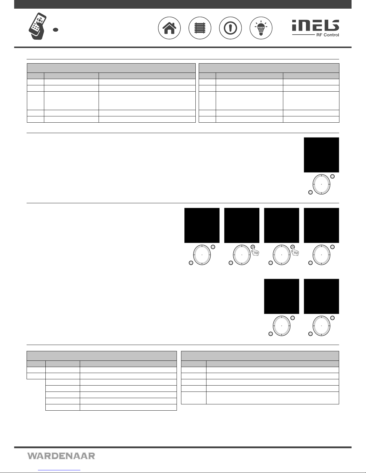
Quick Control
Basic Menu - Control
From the sleep mode you can enter the Basic Menu (Fig.1) in two ways:
- Press any button briefly to display the Initial Scre en. By pressing T1 the Basic Menu will be disp layed.
- By pressing and holding T1 longer than 2 s you can direc tly enter the Basic Menu: Rooms, Scenes, Favourite.
T1
T2
mo 01.01.10 12:54
Rooms
Scenes
Favourite
EXIT SELECT
Fig. 1
Control – Rooms
Menu Rooms is used to control the allocated Actuators.
- Press T1 to enter the menu (the names of Room 1-10 are set as default).
- Select the requested Room using the direction button (up / down).
- By pressing T1 (Fig. 2) enter the list of Actuators allocated to a particular Room (the names of
Actuator 1-10 are set as default).
- Select th e requested Actuator that you want to control using the direction button (up / down).
- Using T1 (Fig. 3) enter the list of functions allocated to a par ticular actuator (Fig. 4).
T1
T2
mo 01.01.10 12:54
Rooms
Scenes
Favourite
EXIT SELECT
Fig. 1
T1
T2
mo 01.01.10 12:54
Room 1
Room 2
Room 3
Room 4
Room 5
Room 6
Room 7
EXIT SELECT
Fig. 2
T1
T2
mo 01.01.10 12:54
Actuator 1
Actuator 2
Actuator 3
BACK SELECT
Fig. 3
T1
T2
mo 01.01.10 12:54
Switch On
Switch O
Brigh: 0%
Slightly On
Slightly O
Setting
BACK PROCEED
Fig. 4
Select the requested actuator function using the direction button (up / down). Send the comman d to execute the selected f unction by pressing T1.
- green s ymbol - command accepted and executed by the actuator (Fig. 1).
- red sy mbol - Error (Fig. 2)
T1
T2
mo 01.01.10 12:54
Switch On
Switch O
Brightness: 0%
Gradual switch ON
Gradual switch OFF
Setting
BACK PROCEED
Fig. 1
T1
T2
mo 01.01.10 12:54
Switch On ×
Switch O
Brightness: 0%
Gradual switch ON
Gradual switch OFF
Setting
BACK PROCEED
Fig. 2
Actuator Function
6/8
Actuator
RFSA-11B
RFSA-6xM
RFJA-12B
RFDA-11B
RFDA-71B
Pressing t he direction al button lef t
Switch Off .
Switch Off .
Simulation of the button on the key-
chain - tilting t he roll-up blinds. Pre ss
and hold to sen d the roll-up blinds up.
Switch Off .
Switch Off .
Pressing t he direction al button right
Switch On.
Switch On .
Simulation of t he button on the Key -chain - tilting the rol l-up blinds.
Press and hold to s end the roll-up blinds d own.
Each pressin g of the button will inc rease the brightness b y 10% (to max. 100%).
Each pressin g of the button will inc rease the brightness b y 10% (to max. 100%).
Controllin g the assigned actuat or (without function)
Actuator
RFSA-11B
RFSA-6xM
RFJA-12B
RFDA-11B
RFDA-71B
Pressing t he direction al button lef t
Switch Off .
Switch Off .
By pressing o nce stop the motion of the ro ll-up
blinds. By p ressing again, set the rol l-up blinds
into motion in th e opposite direct ion.
Switch Off .
Switch Off .
Pressing t he direction al button right
Activates t he set function .
Activates t he set function .
Activates t he set function .
Activates t he set function .
Activates t he set function .
Controllin g the assigned butto n with function
RFSA-11B
Switch Off
Switch On
RFSA-6xM
Switch Off
Switch On
Button
Impulse
Delay On
Delay Off
Setting
Description
Actuator switched On
Actuator switched Off
Actuator contact On when Controller button pressed
Switches the relay output to the opposite position
Switched On with delay
Switched Off with delay
Time setting of delay for switch On / Off within the range of 2s - 60min.
Switching Actuator Functions
RFJA-12B
Up
Down
Turn up
Turn down
Setting
Description
Device moves up to end position
Device moves down to end position
Rolling the blinds/shutters up in gradual steps using short impulses
Rolling the blinds/shutters down in gradual steps using short impulses
Setting Setting the travel time of the device. Measure the travel time from one end position to the
other end position. Set the time data + 2s in the Controller. Range 2s - 240s.
Roller Blind/Shutter Actuator Functions
Page 7
02VJ-004 rev.2
RF Pilot
Wireless remote controller with display
EN
Perenmarkt 10B, 1681PG ZWAAGDIJK-OOST ind.terrein: WFO/ABC THE NETHERLANDS
Tel: +31(0)228-567729, Fax: +31(0)228-567797, Email: info @ wardenaar.com, Internet: www.wardenaar.com
Rabobank 32 69 98 268, KvK te Alkmaar 37079598, BTW NL 8070.48.768.B01
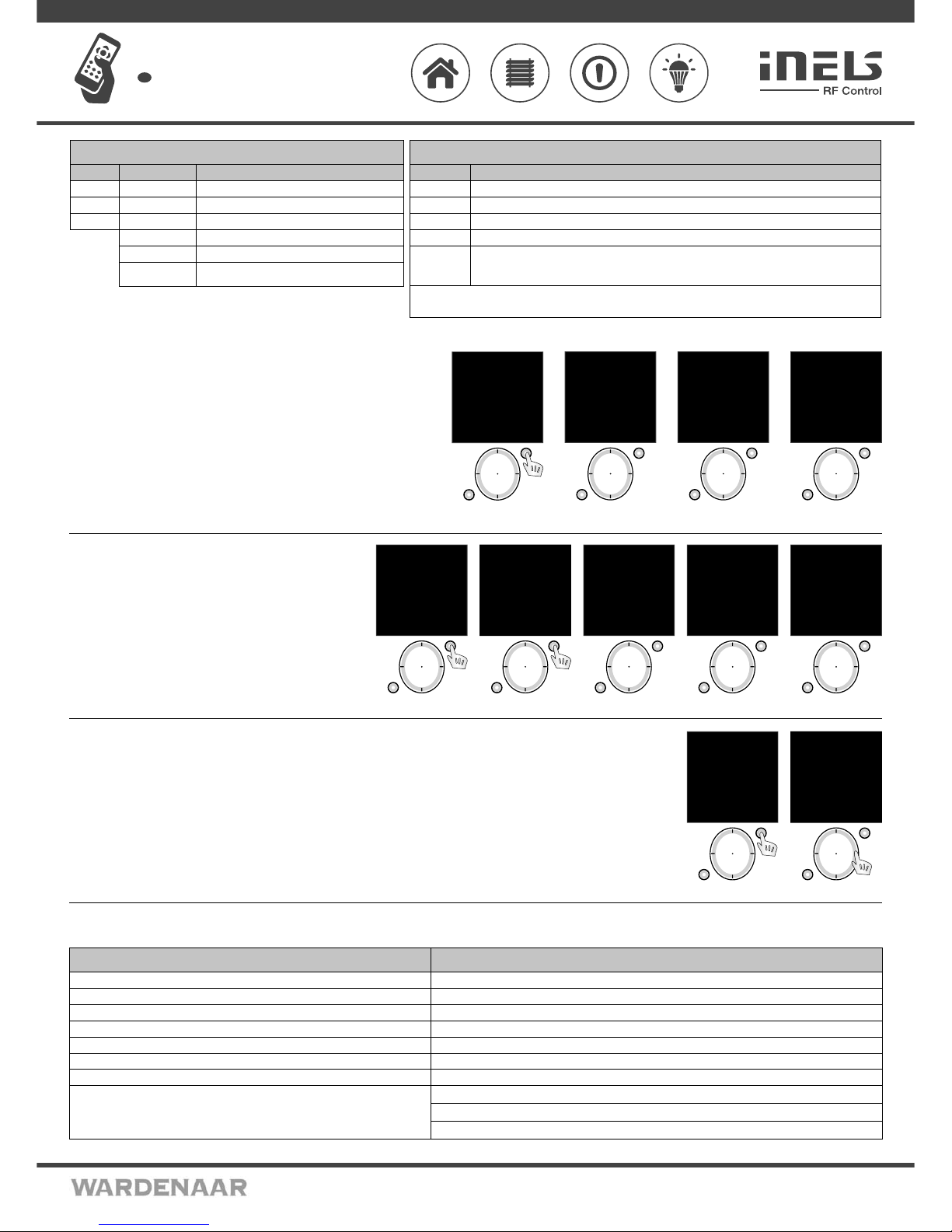
The sett ing serves to define time for each actuator. (Fig. 1).
- Select th e requested data for editing using the direction button (up / down).
- You can set using the direc tion button (right/left):
- in the first line
for RFSA-6x - delayed switch On/Off (Fig. 2)
for RFJA-12 - up / down (Fig. 3)
for RFDA-71 - gradual switch Of f / On (Fig. 4)
- time can be set in the second line
- time units - s/min can be set in the third line (not in the case of RFJA-12)
By pressing T1 save th e setting into memor y and send a setting com mand to the actuator.
- The value has b een saved - the actuator has accepted and saved th e command.
- Communication error - please repeat your command.
T1
T2
mo 01.01.10 12:54
Switch On
Switch O
Brigh: 0%
Slightly On
Slightly O
Setting
BACK PROCEED
Fig. 1
T1
T2
RFSA-6xM
mo 01.01.10 12:54
Delay:
Delay ON
Time: 2 sec
Seconds
EXIT SAVE
Fig. 2
T1
T2
RFJA-12B
mo 01.01.10 12:54
Duration of nish:
Up
Time: 2 sec
EXIT SAVE
Fig. 3
T1
T2
RFDA-71B
mo 01.01.10 12:54
Delay:
Slightly ON
Time: 2 sec
Seconds
EXIT SAVE
Fig. 4
Control - Scenes
Menu Scenes is used to control the allocated commands.
Menu Scenes is selected using the direction button. Press T1 (Fig. 1) to
confirm (the nam es of Scenes 1-10 are set as default). Select th e requested
Scenes using the direction button (up / down). Send a command to
execute the commands by pressing T1 (Fig. 2).
- green s ymbol - command accepted and executed by all actuators
(Fig. 3).
- orange symbol - error (Fig. 4).
- red sy mbol - Error (Fig. 5).
T1
T2
mo 01.01.10 12:54
Rooms
Scenes
Favourite
EXIT SELECT
Fig. 1
T1
T2
mo 01.01.10 12:54
Processing
EXIT SELECT
Fig. 3
T1
T2
mo 01.01.10 12:54
Processing ×
EXIT SELECT
Fig. 5
T1
T2
Fig. 2
mo 01.01.10 12:54
Scene 1
Scene 2
Scene 3
Scene 4
Scene 5
Scene 6
Scene 7
EXIT SELECT
T1
T2
mo 01.01.10 12:54
Processing
EXIT SELECT
Fig. 4
Control - Favourite
Menu Favourite is used to control the allocated Actuators or Scenes.
Menu Favourite is selected using the direction button. Press T1 (Fig. 1) to confirm (names Favourite 1-10 are set as default).
Menu Favourite is controlled in the same manner as Quick Control.
T1
T2
mo 01.01.10 12:54
Rooms
Scenes
Favourite
EXIT SELECT
Fig. 1
T1
T2
mo 01.01.10 12:54
Lamps
Favourite 2
Favourite 3
Favourite 4
Favourite 5
Favourite 6
Favourite 7
Temp.: 23C MENU
Fig. 2
What to do when ...
RF Touch Unit Warnin gs
Warning is displayed in case of incorrect entr y.
Wait approx. 1s between individual button presses.
7/8
RFDA-73M/RGB
Switch On
Switch Off
Brightness
White
RGB
Description
Switching to 100% acco rding to selecte d color mode (white/ RGB)
The act uator will be turne d off
Press joysti ck to the right or to the lef t = you can control the LED s trip brightness f rom 0 – 100 % at intervals of 10%
You activate th e white color
After pres sing a button “Per form”, the color pallet will b e scrolled out, th e color choice is made by joy stick buttons mov ed
to the right or to th e left and then the col or should be confi rmed. Qui ck color choice is made by ho lding a joystick but ton
on the right or t he left.
Funktio n der Dimm-Actuat ors
RFDA-11B
Switch On
Switch Off
Brightness 0%
RFDA-71B
Switch On
Switch Off
Brightness 0%
Slightly On
Slightly Off
Setting
Description
Actuator switched On
Actuator switched Off
Brightness s etting within th e range 0-100% (10% steps)
Graduall y switches On during a p reset time
Graduall y switches Off during a prese t time
Setting t he time of th e gradual s witch On / Off within the
range of 2s - 30 min.
Funktio n der Dimm-Actu ators
There is a mem ory functi on of last used val ue of brightness (l ast used brightn ess setting) = i.e. i f you set the brightn ess to 30 % and then th e
device is turn ed off by o ther wireless trans mitter, so the value 30 % will be kept and saved i n RF Pilot.
Rooms / Scenes / Favourite
Memory full! (when adding actors)
The actuator has already been used.
Low battery indicator on
Communication error!
- orange symbol - error (when controlling scenes)
- red symbol - error
If the error persists:
- The actuator has accepted and executed the command, RF Pilot has not detected any execution
feedback signal
- A part of the actuators have accepted and executed the command (when controlling Scenes)
a fi xed number of places - 10 - is set for each section
No more than 40 actuators may be entered
the actuator has already been assigned to a room
Battery level must be suffi cient to ensure reliable communication with actuators, change batteries
the actuator has not accepted the command, please repeat
some of the actuators has not confi rmed executing the command, please repeat the command
the actuator(s) has/have not confi rmed executing the command, please repeat the command
Low battery
The controller is too far from the actuator(s)
Always check command execution
Warning Cause / troubleshooting
Page 8

02VJ-004 rev.2
RF Pilot
Wireless remote controller with display
EN
Perenmarkt 10B, 1681PG ZWAAGDIJK-OOST ind.terrein: WFO/ABC THE NETHERLANDS
Tel: +31(0)228-567729, Fax: +31(0)228-567797, Email: info @ wardenaar.com, Internet: www.wardenaar.com
Rabobank 32 69 98 268, KvK te Alkmaar 37079598, BTW NL 8070.48.768.B01
Universal information
The displayed temperature is for information only and may be af fected by the placement of the controller near h eat sources, windows, prolonged holding in hand, etc.
Rename Actu ators (Rooms, Scenes) - the min. len gth of the name is 1 character, the ma x. length is 12 characters. Upon d eleting the whole name (by t he T2 button) and confirmi ng (by the T1 button), the
factor y setting is restored (Actuator x, Room x , Scene x).
More Actuators (Rooms, Scenes) may have the same name.
Actuators (Ro oms, Scenes, Favourite) are not sorted alphabetically, but their order is determined by their position in the controller memory.
If an Actuator is removed from the controller memor y, its position in the actuator list becomes vacant. The first vacant position in the list is used to assign the nex t actuator.
Important information
Cleaning and maintenance
• Do not immerse the Remote Controller or its par ts into water or any other liquid! Prevent any liquid from entering into the Remote Controller. The device would be damaged.
• Clean the surf ace using a dry cloth. Do not use aggressive cleaning products or abrasives as these could damage the Controller.
Adhere to the f ollowing instruc tions for batter y use:
• Check the bat teries regularly. Leaking batteries can damage the device.
• If you do not use your Remote Controller for a long time, remove the b atteries.
• Always replace both the batteries at the same time, do not mix bat tery types.
• When inser ting the batteries, always check their p olarity as displayed in the battery compartment.
Beschädigung des Geräts!
• Schützen Sie da s Gerät vor Feuchtigkeit. Verw enden Sie das Gerät nur in trocke nen Roomsn und niemals im Außenb ereich oder in der Nähe von Flüssig keiten. Achten Sie darauf, dass die Fernb edienung
während des Betriebs nicht nass, feucht oder anderweitig beschädigt ist.
• Gerät nicht auf heißen o der der direkten Sonnenbestrahlung ausgesetzten Stellen betreiben o der ablegen.
• Keine Quellen of fener Flammen, wie z.B. Kerzen neben das Gerät stellen.
Device damage!
• Protect the product from moisture. Use the device in dry ro oms only, not outdoors or near liquids . Ensure that the device does not become wet or moist or otherwis e damaged during use.
• Do not operate or leave the device in hot environment, do not expose it to direct sunlight.
• Do not place fire sources such as candles near the device.
Disposal:
Do not dispose of the device together with common household waste. All packaging materials should be disp osed of in accordance with environmentalregulations.
Batteries/accumulators
• Batteries/accumulators must never be disposed of together with household waste. They may contain poisonous substances harmful to the environment. Therefore the batteries/accumulators must
always be disposed of in accordance with applicable regulations.
• Each consumer is obligated by law to dispose of the batteries and accumulators at a local collecting p oint. This obligation ensures that the batteries / accumulators will be disposed of in accordance
with environmental regulations.
Installation Form
Number Description / name of the controlled device Actuator name Actuator address
1.
2.
3.
4.
5.
6.
7.
8.
9.
10.
11.
12.
13.
14.
15.
16.
17.
18.
19.
20.
8/8
Number Description / name of the controlled device Actuator name Actuator address
21.
22.
23.
24.
25.
26.
27.
28.
29.
30.
31.
32.
33.
34.
35.
36.
37.
38.
39.
40.
 Loading...