

Page 1
www.elkoep.com
Installation manual
iNELS RF Control
Page 2

2
4
4
4
4
5
5
5
5
6
7
7
7
8
10
10
11
12
12
13
16
17
17
18
19
20
28
28
29
30
31
34
35
36
Installation manual iNELS RF Control2 3Installation manual iNELS RF Control
INTRODUCTION
We are a traditional and innovative manufacturer
of electronic devices based in the Czech Republic. We are proud to have been your partners in
the fi eld of electrical installations for 23 years.
Thanks to years of experience and our participation in the electronics market, we have become
specialists in electronic module devices - relays,
of which we produce more than 200 types.
Own production, modern apparatus, research and
development center - all this allows us to lead the
development of the most coveted technology
of today, the smart system of electro-installation
iNELS. We develop and manufacture products
that save energy. The iNELS system is an integral
part of passive and low-energy houses.
Product development is inextricably linked with
the development of trade, or, conversely, if there
were no sales - there would be no products. Year
on year increases in sales and business development networks are proof of that. We are always
close to our customers - and always ready with
technical support and a well-stocked warehouse.
You will fi nd our o ces in eight European and
two Asian countries. In addition, we have de-
INTRODUCTION
1. THE DIFFERENCE BETWEEN WIRED AND WIRELESS INSTALLATIONS
1.1 iNELS RF Control is ideal
1.2 How the iNELS RF Control can control an extensive installation
1.3 Types of communication
2. GENERAL COMMUNICATION CONTROLS (STANDARD)
2.1 iNELS RF Control - RFIO
2.2 Versions of iNELS RF Control
2.3 Advantages of RFIO
2.4 Frequency 433 vs. 868 MHz
3. BASIS OF HIGH QUALITY INSTALLATION FOR A SATISFIED CUSTOMER
3.1 What to avoid in the installation
3.2 The biggest myths about smart homes
3.3 What components iNELS RF Control o ers
3.4 How to read the type designation
3.5 Installation
3.5.1 Where to install devices
3.5.2 What can interfere with RF communication?
3.6 Power
3.7 Installation/placement of controllers and system components
3.8 When to use a repeater
4. CONNECTION COMPONENTS FOR LOAD SWITCHING/OUTCOMES
4.1 Switching components
4.2 Dimming components
4.3 Temperature components
5. SET DESIGN ELEMENTS WITH CONTROLLERS AND SYSTEM UNITS
5.1 What else you should know when you install
5.2 Compatible cameras
6. BACKUP/UPDATE UNITS, RF TOUCH OR RF PILOT
6.1 Backup parameters/update units eLAN-RF
6.2 Did you know that...
7. WHY SELL iNELS RF CONTROL
8. WHAT CAN YOU CONTROL?
9. iNELS REFERENCES
pendable customers in more than 66 countries
and more are constantly being added as demand
is constantly increasing for our products. Our
products can be found under the brand names
of world (Schneider Electric, Eaton, Hager, Siemens, NIEAF SMITT).
Development and modern technology are the pillars of our work, which in practice is appreciated
by you - our customers. You get not only products, but also customized solutions - according
to your requirements. Our own development facilities and meticulous production and distribution combines to give you the opportunity to use
solutions which are both innovative and practical. We produce all our products in our modern
production facilities, which has been expanded
by including the latest SMD and fastest production line, which means you are guaranteed quality and fl exibility of supply.
The installation manual is intended for system
partners/developers as it makes recommendations for installation and a comprehensive introduction to wireless technology, iNELS RF Control.
Page 3

Installation manual iNELS RF Control4 5Installation manual iNELS RF Control
In conventional electrical wiring, cables are routed
from the distribution box to the outlets, switches and
lights. Using a wireless system, since it is possible to
use battery powered switches, the cables leading to
the switches are eliminated. Another great advantage are the subsequent functions which are a given
for a standard switch. With a wireless switch it is possible to select the functions to switch on/of, time
delay the lights and reset or adjust these functions at
anytime. An indisputable benefi t is the ability to control the selected light circuit from multiple locations
or it can be connected with other lighting circuits.
Ideal in the use of reconstruction, to which any device
can be added. Alternatively, if you want to start living
in a smart home, but do not know whether the house
will comply with the system. Or when the fi nancial
costs incurred in the construction of the house do
not allow room for automation with a high initial investment. The big advantage of iNELS RF Control is
that you can start with a simple set and expand the
system as desired or when fi nance allows.
Generally, fi rms rush into the installation of multiple
components (which are often in their thousands).
Experienced system partners (who are engaged in
installing wireless systems), say that the building is
suitable for installing a max. 40 to 50 components
without having to adjust to a complex path of sw, or
if the signal is lost, this results in a subsequent relationship issue with reliability.
1. THE DIFFERENCE BETWEEN WIRED AND WIRELESS INSTALLATIONS
1.1 iNELS RF Control is ideal
1.3 Types of communication
1.2 How the iNELS RF Control can control an extensive installation
• One Way
The downside is that you do not know whether the
message has reached the component or not.
• Bidirectional
For the transmission of data “routing” via components - using a repeater
• Mesh
Sometimes there is a requirement to correct the sw
signal path due to delays.
controller component
component
component
component
obstacle
obstacle
controller
RFIO is a proprietary protocol from ELKO EP, which it developed in 2005 and it is constantly improving. Communication is intended not only for simple commands such as switching lights, but also for receiving/transmitting
the values of temperature or consumption. The RF module was tested at the Institute of Electronic Communications and items subject to standards FCC, EN 60669, EN 300 220, EN 301 489 R & TTE Directive, Vč.426/
2000Sb. The system operates at a frequency band of 868 MHz/916 MHz (for automation), wherein the transmit
power of the RF module (integrated in the components) 25 mW. This brings great results applied across the frequency range of installations. Components communicate among themselves bidirectionally and with adjustable
routing through other components (each component can be used as a repeater).
2. GENERAL COMMUNICATION CONTROLS (STANDARD)
2.1 iNELS RF Control – RFIO
Available frequencies in each area:
controller
component
866 MHz India
868 MHz EU, UA, RU, Middle east
916 MHz North / S outh America,
Australia
922 MHz N ew Zealand
• 2008-2009
- Components marked RF Control (one-way communication).
2.2 Versions of iNELS RF Control
• 2009-2014
- Oasis & RF Touch compatible (compatible with
Jablotron Oasis 80 detectors system and the RF
Touch). The di erence between Oasis 80 and RF
Touch is a one-way vs. two-way communication.
• 2015-2016
...RF Control components are bidirectional.
• 2016...
....RF Control 2, setting routing through the compo-
nents.
Individual versions are compatible with each other
(except version 2008-2009).
• the RF module (RFIO) does not tie the customer
or system partners to any licenses or other fees
associated with the software
• each subsequent version of iNELS since 2009 is
compatible with each other
• guaranteed all elements, features between each
other to be 100% compatible
• setting communication between the components is not conditional on a computer or Internet connection, the same is true for the actual
2.3 Advantages of RFID
Command (message) is broadcast fi ve times, during which, if the element responds the fi rst time,
the band continues with no unnecessary communication fl oods. If the command does not arrive even
once the whole process is repeated. If re-commanded (which can also be temperature information) is
received, specially with temperature, information is
transmitted to turn o components.
See. Fig. p. 6 - Functional diagram RFIO
operation of the system = works without internet connection
• data is stored in the products, not in the cloud
• if a system partner wants a program within the
system itself, we provide an Api for free (As opposed to standard)
• RFIO does not overwhelm space for unassigned
commands
• single setup control component and you do not
need to set any additional software or programming tool
Page 4
Wi-Fi
Router eLAN RFDEL
RFJA
LARA
RFSA
23
21°C
18 202225
Installation manual iNELS RF Control6 7Installation manual iNELS RF Control
• Certifi cation iNELS RF Control:
The RF module was tested
at the Institute of Electronic
Communications and items
are subject to standards ČSN
EN 60669, EN 300 220, EN 301
489 directive RTTE, NVč.426 /
2000Sb (directive 1999 / ES).
According to the general authorization for the use
of radio frequencies for the operation of short range
devices for not specifi ed stations The maximum radiated power is limited by law to 10 mW at 433 MHz
frequency band and to 25 mW at 868 MHz frequency band.
With the maximum radiated power relating to the
distance at which these devices can communicate.
433 MHz band is mostly used for communication
solutions for short and medium distances. Up to 50
m or thereabouts. It provides a cheap and easy way
to connect two devices. However, this band is very
busy and may cause interference with other devices
operating at this frequency.
Rules for 868 MHz band are more restrictive than
those for the 433 MHz band. The distance over
which two devices can communicate is about 200
m, It can be called the mid-size range. Interference
with other devices operating in the 868 MHz frequency is thus reduced, providing better quality information transmission.
2.4 Frequency 433 vs. 868 MHz
FCC certifi cation is a condition
of the sale of wireless system
iNELS RF Control for USA. It is
a rigorous certifi cation, which
confi rms that electromagnetic interference (EMC) of the
device iNELS RF Control is
within the limits approved by
the Federal Communications
Commission. and Examination and obtaining certifi cation without any problems
is proof of the quality of the
entire system. In the production of the products iNELS RF
Controls undergo double fi nal
inspection before leaving the
headquarters of the fi rm.
3. BASIS OF HIGH QUALITY INSTALLATION FOR A SATISFIED
CUSTOMER
• o er (in the form of an iNELS checklist )
• beta testing with customers
• giving up with a problem in the work
• do not say that the system is perfect and never
goes wrong
• do not just take big orders, even a small job makes
for signifi cant marketing
• subsequent calculation program for calculating
the quote (supplied free)
• installation according to manufacturer‘s recommendations
• service
3.1 What to avoid in the installation
1. Installation is expensive.
You can start from 48 EUR.
2. Harmful to health.
If we take into account that you do not have a microwave at
home and not using a cell phone (or cordless doorbell) yes.
3. Someone could hack into my house operation.
Impossible. If you do not disclose your access data to third
parties.
4. What if the electricity fails?
You can have a backup power source in the form of a battery. And when it does fail...nothing. Once the electricity
is switched on, the system checks its self. All preset pro-
3.2 The biggest myths about smart homes
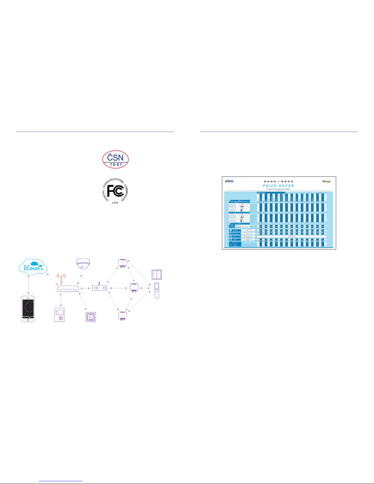
Functional diagram RFIO
Control devices
RFWB, RF Pilot
Home
Videophone
Mobile
Application iHC
Camera
actual temperature
heating 1
temperature
The fi rst step to a successful installation is fi lling the check list, where your customer marks, „what he wants to dominate,“ then „as a means to control“ and then calculated by the partner using the software tools to easily tailor the o er.
grams are as they were, it runs, starts and re-starts
5. What if the battery control runs out of power?
The system indicates low battery, you simply replace the
battery. These are common types of batteries, available
in every watchmaking and Appliance Store.
6. Do I Need Smart Home?
No, you do not need, but you do not need a car, a washing machine, smart telephone and many other technologies. However, it‘s a lifestyle.
7. Will I save?
Defi nitely yes, it can save up to 30% on heating costs with
regulation; depending on whether or not you are at home.
More savings from switching the boiler to run only at
a time when energy is cheap (TOR. HDO).
8. I can handle the control system?
If you have a smart phone or know how to fl ick a switch
fi rmly Yes, the whole operation is adjustable according
to your wishes.
9. What if my grandma comes to stay Will she be able to light
up?
The smart system can be combined with the existing
electrical wiring.
Page 5
RFWB-20/G RFWB-40/G RF Key RF Pilot RFIM-20B RFIM-40B RFSG-1M
RFDA-73M/RGB RFDEL-71B RFDEL-71MRFDSC-71 RFDAC-71B
RF Touch-B RF Touch-W eLAN-RF-003 eLAN-RF-Wi-003 RFGSM-220M RFRP-20 RFPM-2M
RFJA-12B/230V RFJA-12B/24V DCRFSC-61 RFUS-61
RFSA-62B RFSA-61MRFSA-11B RFSA-61B RFSA-66MRFSAI-61B
RF RF
:
:
RFATV-1 RFSTI-11B
RFSTI-11/G RFTI-10B RFTC-10/G RFTC-50/G
RFTC-100/G
RFSOU-1 RF-RGB-LED-550
RF-White-LED-675
RFSF-1B
FP-1
RFTM-1
RFSD-100/
SD-100
RFMD-100/
MD-100
iNELS Cam
RFWD-100/
WD-100
CT50Telva
TC/TZ
AN-I
AN-E
LS, MS, IRS
Installation manual iNELS RF Control8 9Installation manual iNELS RF Control
st 01.05.16 12:54
Místnosti
Scény
Oblíbené
ODEJÍT ZVOLIT
Wireless remote
control with display
4-button controller
- key-chain
4-button wireless
wall controller
2-button wireless
wall controller
Wireless contact
converter (4 outputs)
Wireless contact
converter (2 outputs)
Wireless contact
converter
Controllers
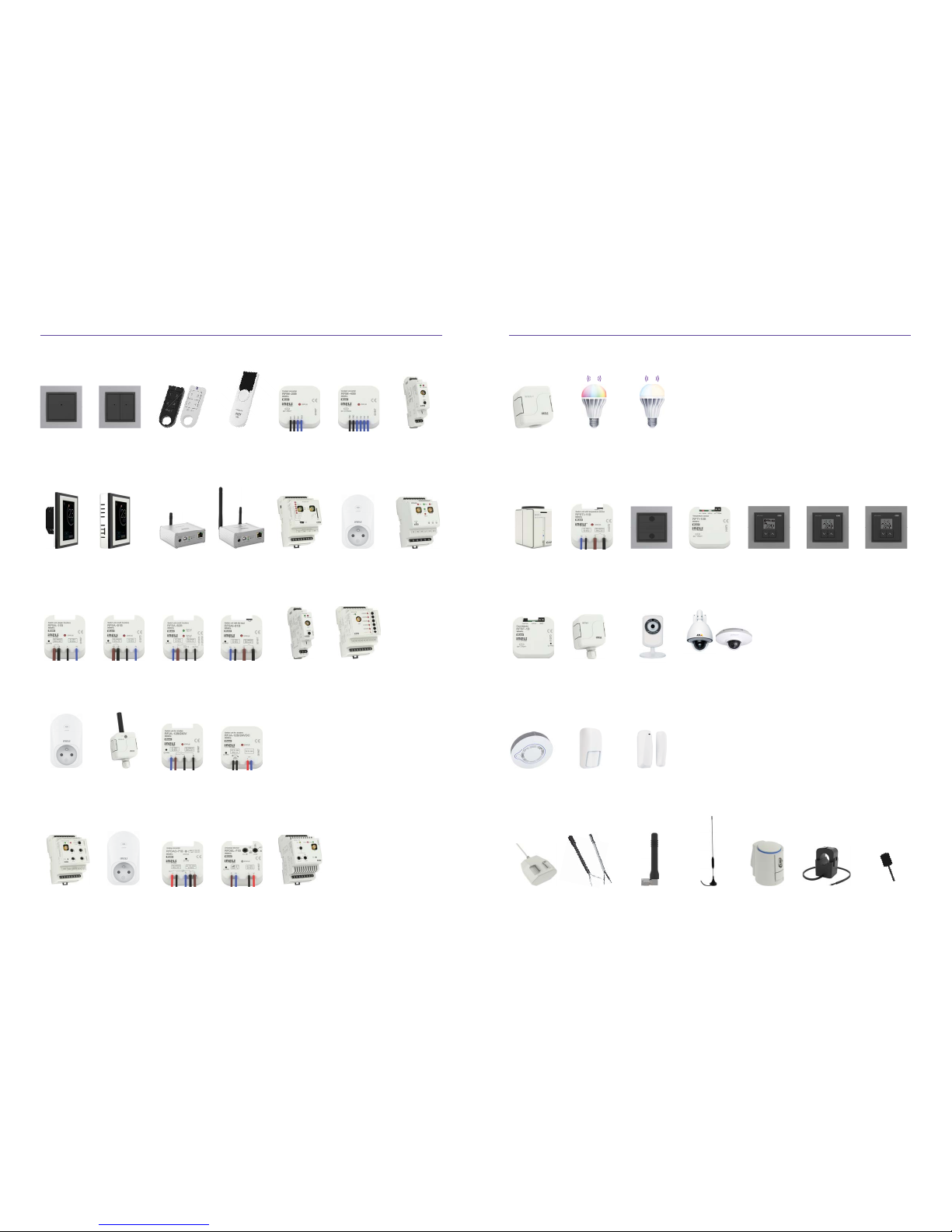
3.3 What components iNELS RF Control o ers
Lighting
Wireless twilight
switch
Wireless colour bulb Wireless white bulb
System Units
Wireless touch unit
- Flush mounting
Wireless touch unit
- Surface Mounting
Multifunction GSM
communicator
Smart RF box with
Wi-Fi
Signal repeaterSmart RF box Energy gateway
Wireless temperature
sensor
Temperature Regulation
Switch unit with
temperature sensor
(fl ush mounted)
Switch unit with a
temperature sensor
and breaker
Wireless thermovalve Wireless temperature
controller
Simple wireless
temperature
controller
Wireless temperature
controller
Analog regulator
0 (1) -10V
Dimmers
Universal dimmer
(recessed)
Universal dimmer
(Modular)
Dimmer socket
(multinational)
Dimmer for color
(RGB) LED strip
Switch unit for
shutters
Switch unit for shutters
(Contact-less)
Switch unit for outdoor
use (multi-function)
Switching socket
(multi-function)
Switches
Wireless switch unit
(inbuilt) - 2 outputs
Wireless switch unit
- 1 output
Wireless switch unit
- 6 output
Wireless switch unit
with input for
a pushbutton
Wireless switch unit
(multi function)
- 1 output
Wireless switch unit
(single function)
- 1 output
Monitoring Units
Wireless fl ood
detector
Wireless pulse
converter
Detectors
Smoke detector
wireless/wired
Motion detector
wireless/wired
Door/Window detector
wireless/wired
IP camera Supported cameras
Cameras
Flood probe
Accessories
Current transformerThermodriveTemperature sensor Internal antenna External antenna LED sensor,
Magnetic sensor,
Infrared sensor
Page 6
R
F
S
A
6
2
B
R
F
D
A
7
3
M
60-90% 20-60%
0-10%
80-95%
80-95%
0%
0/10
RFSTI-11/G IN
RFSTI-11/G IN
Installation manual iNELS RF Control10 11Installation manual iNELS RF Control
In the iNELS RF Control product range every component has a type designation from which you can
determine its functions, assembly and outputs.
3.4 How to read the type designation
Radio
Frequency
Switching
Actuator
function
outputs (channels)
box
Radio
Frequency
Dimming
Actuator
function
outputs (channels)
modul
Location of the components depends on the distance
between the controller (the system unit) and the component, the material through which the signal passes
plays an important role in component placement.
Range in an open area is 200 m, but this fi gure is only
an approximation for real installation orientations.
3.5 Installation
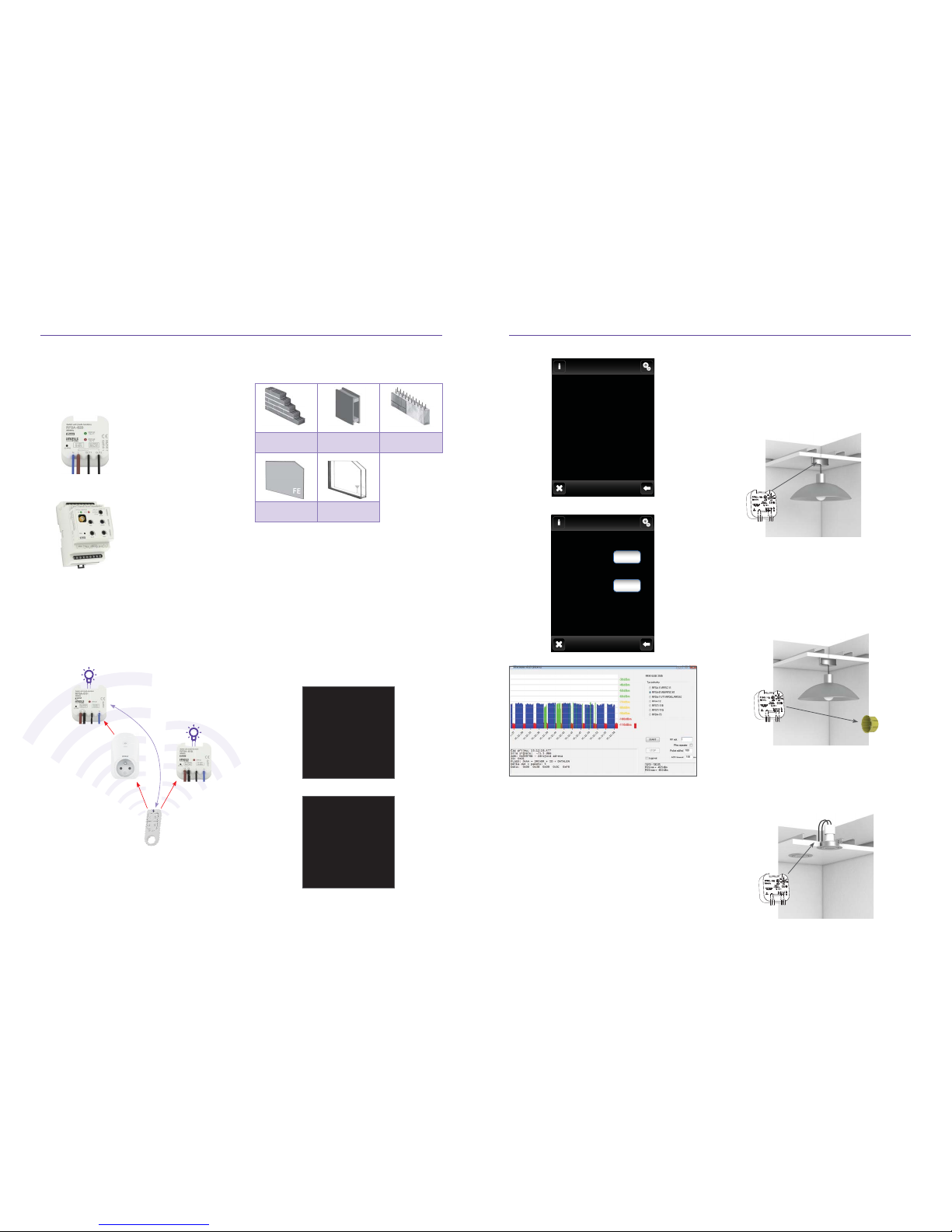
brick wall
wooden construction
with drywall. boards
reinforced concrete
metal partitions ordinary glass
Before installing, it is necessary to measure the signal quality between the individual components. This
procedure is often underestimated, but it is an important fi rst step towards the installation.
Measurements can be made using the control touch
unit RF Touch or remote RF Pilot (which have the
range test function). It is recommended to use the
RF test pilot for this, because it is a fl exible controller and battery-powered. The component is placed
at the installation site and the aforementioned control tests the signal quality.
Order of magnitude, if you get below 30% signal
quality, it is necessary to relocate the component to
maintain 100% functional.
mo 01.01.16 12:54
Test actuator cable:
Packets: 0/10
Signal status 0%
CONTINUE
mo 01.01.16 12:54
Add
Assign
Rename
Range test
Control
Remove
EXIT SELECT
Therefore, it is important to proceed according to
the following points, to ensure the best possible visibility of the controller (system unit) and the component. Transmission in a brick building through 5 walls
(width 20 cm) is in the order of 40 m. Conversely
when you install elements, the minimum distance
between components should be at least 1 cm.
Transmission of radio frequency signals in various
building materials:
RANGE up 400 m
RANGE
up 200 m
RANGE
up 200 m
RANGE
up 200 m
Test
progress
Signal
strenght
Return to Programming
Start
Communications test
Remove
Pair it with ...
Paired with ...
Change address
Function
Another way to check the communication range (of
the system components) of the installation is using
the RF Tester (battery powered) and USB fob RFAF,
which is connected to the PC. The principle of the
test is the location of the system component to the
installation site (e.g. ELAN).
PC should be placed close the system unit and open
the software with RF scanner (do not forget to connect the RFAF to the USB).
Subsequently you go through the RF TESTER with
the components to be installed in places where they
will be installed On the PC, you can see the quality
of the signal. When it is less than 30% it is better to
relocate the component.
The ideal place for mounting components is in direct line of sight of the iNELS RF Control (eg. light
fi ttings). Because it is located in the center of the
room and has direct visibility to the controller (if
there is a system controller).
3.5.1 Where to install devices
Another fi tting space is in an installation box, where,
thanks to the size, wireless devices fi t seamlessly
(such as a high volume installation boxe.g. KU-68).
Tip: the space in the installation box is particularly
suitable if you want to keep the existing control button and combine it with wireless - this can be done
with components RFSA-61B, 71B-RFDEL.
It is convenient to mount components in ceilings,
which o ers plenty of space. Tip: Each dimmer produces heat which has to be dissipated, when mounted in the ceiling this is resolved, because there is
generally more space).
Page 7
☺
☺
☺
☺
☺ ☺
Installation manual iNELS RF Control12 13Installation manual iNELS RF Control
receiver
transmitter
GSM/Wi-Fi...
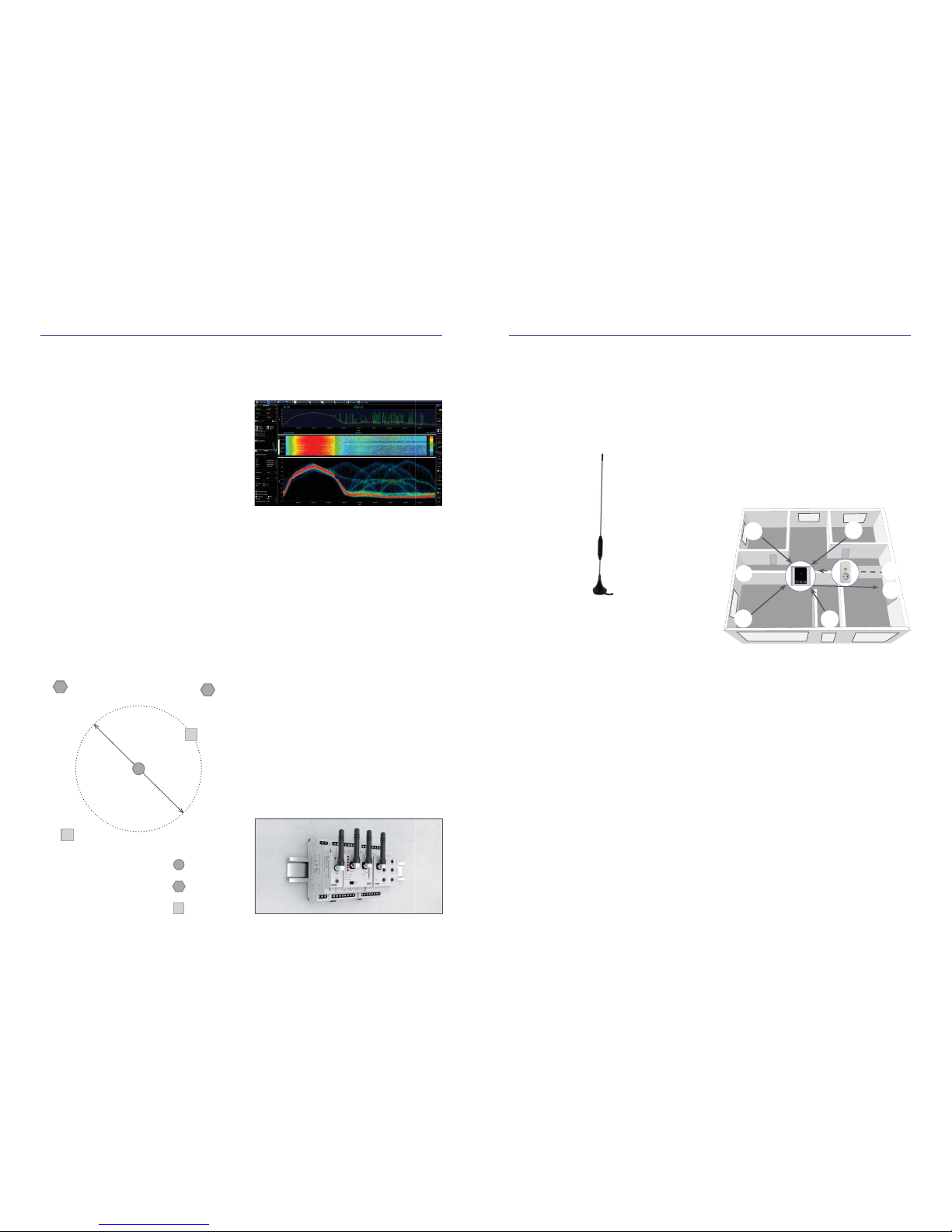
How can you identify the interference or signal source?
The type device which scans the area is called a spectrum analyzer.
The power of our controllers, components and system units is 230 V AC (50 Hz), 110-230 V AC (50 Hz),
120 V AC (60 Hz) - US 12-24 V AC/DC and battery
CR2032 AA or AAA batteries. The components are
powered by mains voltage with a power tolerance of
+ 10% - 15%.
Perhaps the greatest challenge for the customer
is the life of the battery. On the market there are
controllers with piezoelectric power (especially
EnOcean) to function they do not need any other
power, but the disadvantage is a ridged handshake
and signifi cantly higher noise levels. Battery replacement is quite simple.
Weak batteries have charge level components that
signal the low level, this is indicated on the application or the touch control unit RF Touch. Replacing
the batteries in the remote control comes without
lose of the set programs, they are stored in memory.
Generally, temperature infl uences battery performance. Temperature instability can signifi cantly reduce the reliability of backup batteries and to some
extent complicates the stable operation of the battery. Batteries reach nominal characteristics at temperatures around 20 °C and higher temperatures
leads to shortened service life and frequent battery
exchanges. For example, if the ambient environment
temperature is persistently higher by only about
5 °C it can shortened service life by about 25 to 30 %.
Installation of the components to the distributor is
a given and must be suitable for the switching of sock-
3.6 Power
In the event that the components are install next to
each other, they must have a gap of at least 1 cm between them. If circumstances do not allow this distance to be observed A metal foil is used to separate
the components in the broadcast signal.
This design of component provides switching and
dimming features and the socket is installed directly
to an existing outlet (French, British, US design).
The design elements of the IP65 means that the
product (electronic part) is protected against accidental contact with any tool (dust proof) and protected against water ingress. Water through a 6.3
mm nozzle at all angles at a fl ow rate of 12.5 liters per
minute at a pressure of 30 kN/m
2
for at least three
minutes from a distance of 3 m. They are installed in
garages, garden houses, cellars, greenhouses,...
RFWB-20/40 wireless switches it is possible thanks to
the fl at base to mount on an existing installation box
or stick to practically any material, even on glass.
The RF Touch system controller is o ered with a wall
box mounting (in case of 230 V). It is possible to
attach to the wall by means of adhesive (with power
adapter).
For Smart boxes eLAN installation is arbitrary, but for
best results they are mounted farther away from disturbing elements, such as routers, servers, rack,...
3.7 Installation/placement of controllers and system components
ets or lighting circuits. Here you should avoid enclosing components in metal, as iron does not allow
signals to be received and creates a Faraday cage.
Tightening torque of the terminals (distributor components) is a standard 0.4 Nm.
If the component must be placed in a metal cabinet,
it is necessary to use an external antenna. Tightening torque of the antenna is 0.56 Nm.
If the signal is weak there can be a source of interference called. router interference = If there are several Wi-Fi networks, and they are installed near the
transformer station, which produces EMC. Disruptive
infl uencees can be caused by a non-certifi ed wireless doorbell, but also from the microwave (especially at a frequency of 433 MHz). In practice it may
happen that seemingly permeable material such as
glass, becomes impermeable and especially in cases
where aluminum foil it is installed on the glass.
Wall material can be made of anything, and sometimes it‘s hard to fi gure out what it is. The biggest
loss (of signal) is delivered by building reinforcement girders, Steel casings and steal within the walls
of industrial buildings. Here you can use a commercially available metal detector to install a wireless
system, The result of such an installation refl ect
electromagnetic waves, like that of a mirrored surface that refl ects light and so creates an electromagnetic shadow. For small objects such as bolts,
nuts, screws, nails, this phenomenon can be omitted.
It is necessary to take into account that components
or the system controller installed directly into the
wall box (which is in the vicinity of electrical cables)
can bring about a loss of signal strength up to 30%.
The same is true when installed on metal surfaces.
Distances from other sources of interference
The respective distance of components or the system unit from other transmitters, sources of interference (eg. GSM device/Wi-Fi/weather stations, etc.)
should be at least 1.5 meters.
3.5.2 What can interfere with
RF communication?
RFIM-20/40 wireless transmitters are installed in an
existing installation box under switch/button technology, from where they transmit a signal.
Between the controller and the component there must
not be a distance of less than 1 cm.
Basically you should place controllers such as the wireless switch RFWB with the best possible visibility to
the component, you must ensure that the signal does
not pass through walls diagonally.
Between the controller and the component there must
not be a distance of less than 1 cm.
System controllers are installed with the best possible
access to all the components, usually in the middle of
the house or room where the components are.
External Antenna AN-E
2 m
2 m
Page 8
50 m
100%
100%
100%
100%
80%
100%
100%
100%
100%
80%
☺
☺
☺
☺
☺
☺
☺
Installation manual iNELS RF Control14 15Installation manual iNELS RF Control
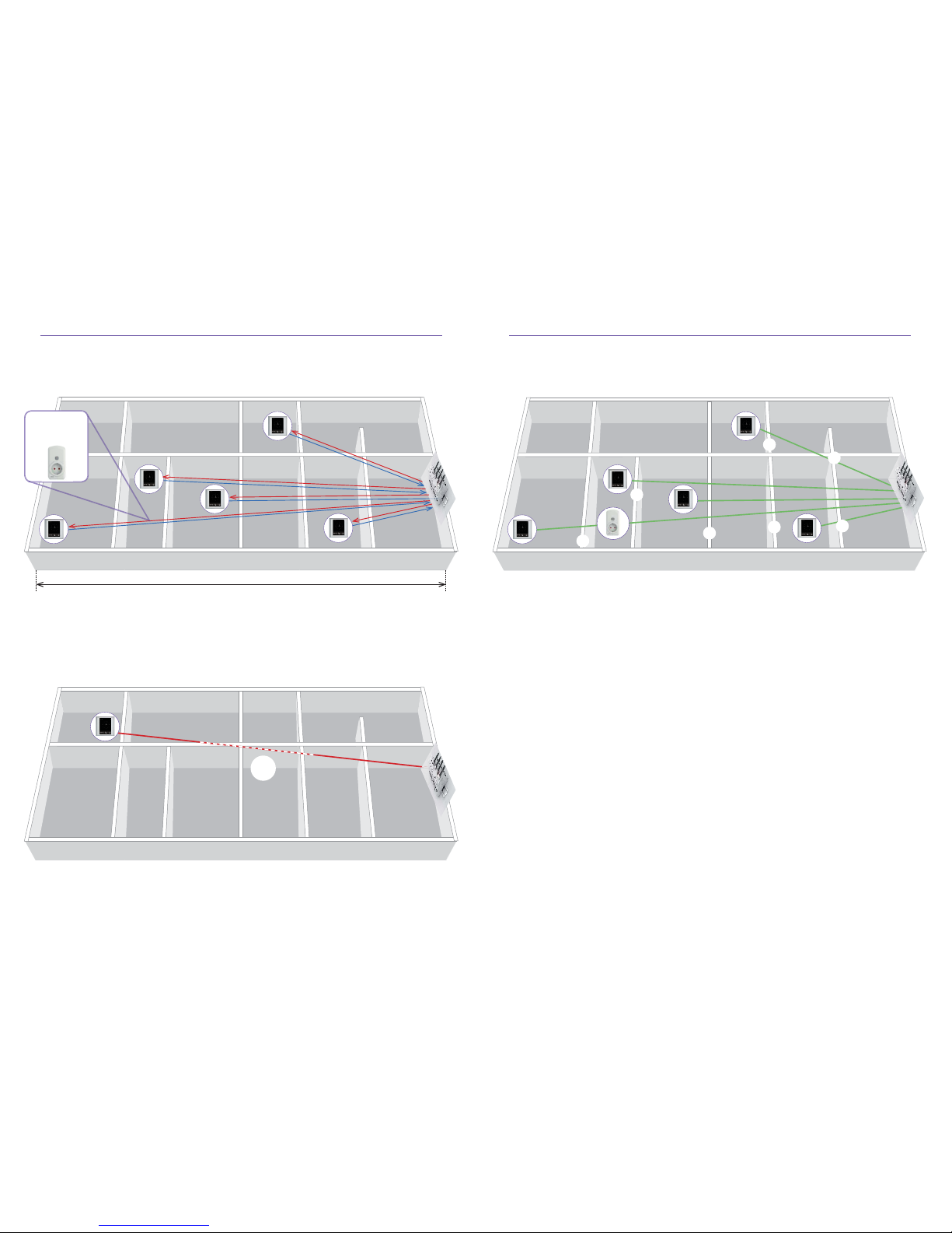
A real example of the range of RF Touch in a house where it was set to command „Scenes“ for switching 20 compo-
nents The fi rst house is built of bricks, the depth of the wall is about 20 cm.
panel and RF
components
panel and RF
components
panel and RF
components
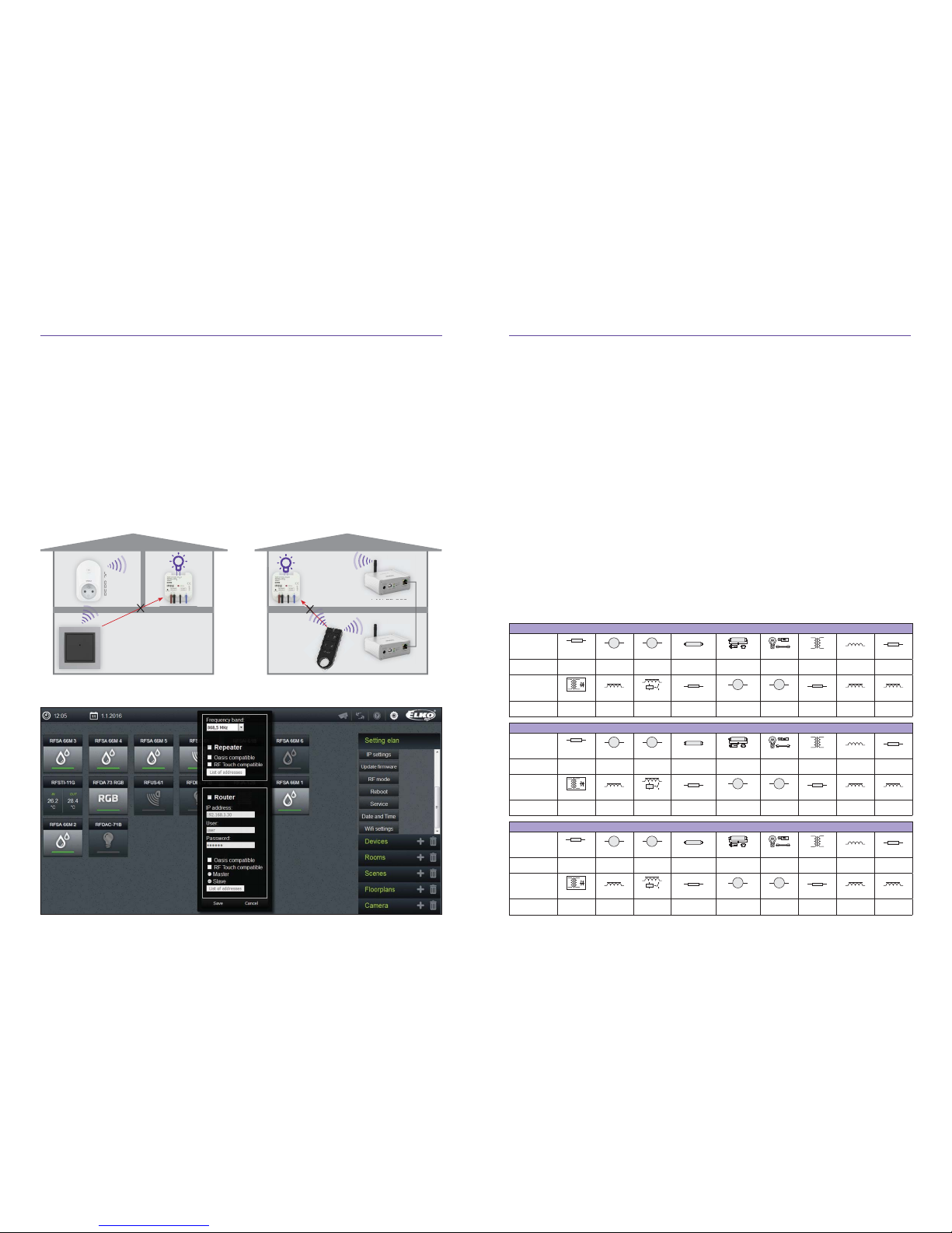
To determine which component placement to avoid?
Diagonally, the signal passes through the material thereby increasing the risk of wireless failure.
we recommend
using a Repeater
to extend range
What is the optimal signal passage?
When the signal passes (between the controller and the component) directly through the material.
Page 9
Installation manual iNELS RF Control16 17Installation manual iNELS RF Control
zanine, so that it can allow the signal to bypass the
metal barrier and arrived at the component.
One repeater RFRP-20 can route (transfer) the signal
of 20 components. In one installation, we recommend
to use a max. of 2 routers, so as not to delay the signal and reaction.
A repeater may have a problem with the signal transmission between fl oors (which are mostly made of
reinforced concrete and thus become impassable for
RF signals). The solution is to use two eLANs in the
installation connected by LAN cable.
Spínací prvky nabízíme s napájením 230V AC a také
s napájením 12-24AC/DC, díky tomu máte široký
rozsah použití.
It is important to look at the value of the switched
current vs. contact. iNELS RF Control components
have 16 A contacts in single channel version 8 A in
multichannel. Using a relay from reputable brand
TYCO Electronics, where the number of switching
cycles is more than 3 million (depending on the switching load). Peak current at contacts 16 A and up to
30 A for a max. of 3 s.
Equally important is an indication of the contact material. iNELS RF Control uses in its switching components AgSnO
2
contacts, which is designed for switching the resistive and capacitive loads. Often you
can see (especially in non-reputable manufacturers)
the contact AgNi, which is only for resistive loads
(when connected the CFLs would explode).
The most widely used load:
AC1 – resistive load (incandescent bulbs)
AC3 - motors
AC5 - fl uorescent
AC15 – contactors
4. CONNECTION COMPONENTS FOR LOAD SWITCHING/OUTCOMES
4.1 Switching components
A good guideline of the type and the maximum value of the switching current in the following table:
If the RF Pilot displays a weak signal range (less than
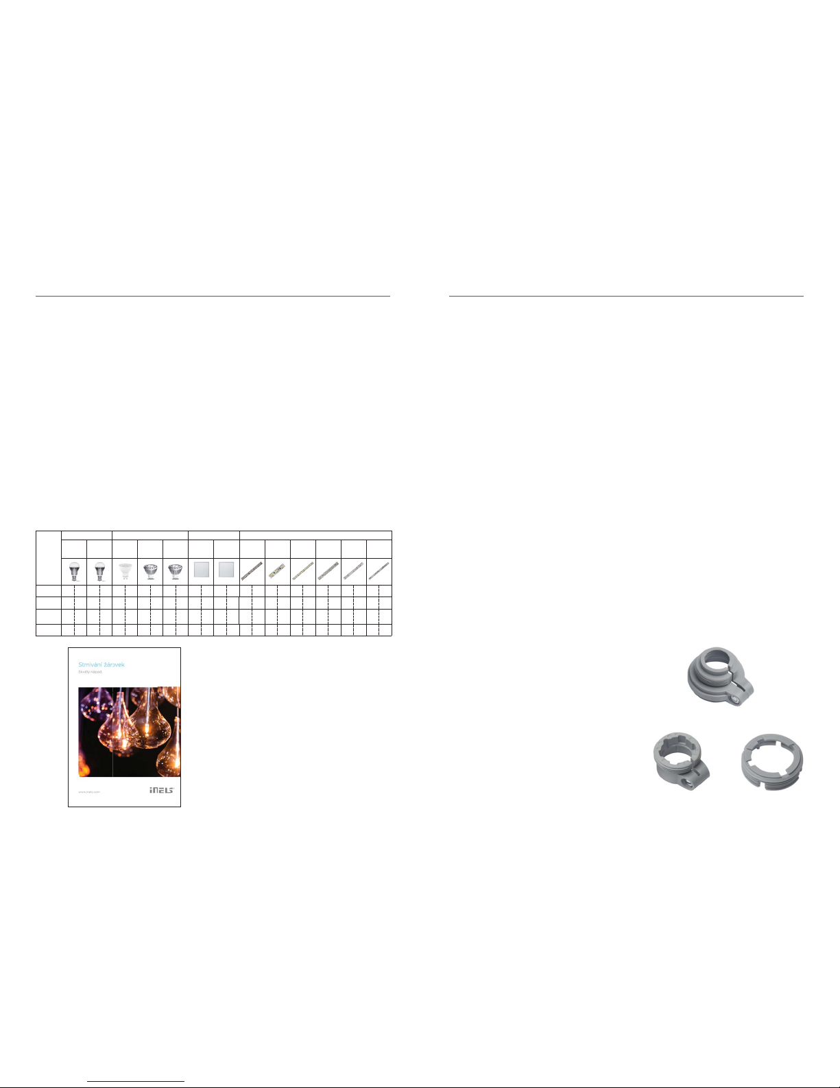
30%), but it s not possible for the installation component to move, we can use a repeater. This unit receives
the signal, amplifi es and resends the signal. Thanks to
this, you can control components that with the fi rst
measurement without a repeater the signal strength
was below 30%. We recommend a maximum of 2 repeaters in wiring due to delays. The Repeater should
always be as close to the obstacle, so that it is visible
from both sides (transmitter and receiver) and the
signal can bypass the impassable obstacle.
Example:
If in between the house fl oors there are metal barriers
that prevent the passage of signals a repeater must
be used. Repeater at this time is placed in the mez-
3.8 When to use a repeater
The advantage of RFSA-61M or RFSA-66M components is a switching contact, which can trigger the
activation or unhook the contact of controlled appliances.
Working temperature of the switching components
is -15 ... 50 °C.
Switching element RFSA-61B has terminals (input)
control buttons. The maximum cable length should
not exceed 10 m and should not go in parallel with
power lines...
Switching components available with 230V AC and
Power 12-24AC / DC, because you have a wide range
of applications.
Switching shutter components RFJA-12 have a 230 V
power supply and a 12-24VDC power output supply
where it is more suitable to control almost all of the
components. These components send to the system
unit, location information entirely up / completely
down but not send any information about their condition, in the case of intermediate positions.
The setting takes place via a web interface.
RFJA-12B; RFSA-62B; RFSA-66M; RFSTI-11/G; RFGSM-220M
load type
cos φ 0.95
M M
HAL.230V
AC1 AC2 AC3
AC5a uncompensated AC5a compensated
AC5b AC6a AC7b AC12
mat. contact AgSnO
2
contact 8A
250V/8A 250V/5A 250V/4A x x 250W 250V/4A 250V/1A 250V/1A
load type
K
M M
AC13 AC14 AC15 DC1 DC3 DC5 DC12 DC13 DC14
mat. contact AgSnO
2
contact 8A
x 250V/4A 250V/3A 30V/8A 24V/3A 30V/2A 30V/8A 30V/2A x
RFSA-11B; RFSA-61B; RFSA-61M; RFSTI-11B; RFDAC-71B , RFSC-61, RFSAI-61B
load type
cos φ 0.95
M M
HAL.230V
AC1 AC2 AC3
AC5a uncompensated AC5a compensated
AC5b AC6a AC7b AC12
mat. contact AgSnO
2
contact 16A
250V/16A 250V/5A 250V/3A 230V/3A (690 VA)
230 V/3 A (690 VA)
max. input C=14uF
1000 W x 250V/3A 250V/10A
load type
K
M M
AC13 AC14 AC15 DC1 DC3 DC5 DC12 DC13 DC14
mat. contact AgSnO
2
contact 16A
x 250V/6A 250V/6A 24V/10A 24V/3A 24V/2A 24V/6A 24V/2A x
RFUS-61
load type
cos φ 0.95
M M
HAL.230V
AC1 AC2 AC3
AC5a uncompensated AC5a compensated
AC5b AC6a AC7b AC12
mat. contact AgSnO
2
contact 12A
250V/12A 250V/5A 250V/3A 230V/3A (690VA)
230V/3A (690VA)
max. input C=14uF 1000W x 250V/3A x
load type
K
M M
AC13 AC14 AC15 DC1 DC3 DC5 DC12 DC13 DC14
mat. contact AgSnO
2
contact 14A
x 250V/6A 250V/6A 24V/10A 24V/3A 24V/2A 24V/6A 24V/2A x
RFRP-20
RFWB-20/G
RFSA-61B
RFSA-61B
eLAN-RF-003
eLAN-RF-003
RF KEY
Page 10
Installation manual iNELS RF Control18 19Installation manual iNELS RF Control
For dimmers in general, the output vs. maximum load
should not be more than 70%.
Furthermore,dimmer cooling is a valid concern therefore do not install dimmers next to each other or with
another source of heat (or contact, whose switching
produces EMC and thereby may a ect the correct
operation). For all ELKO EP dimmers there is an integrated thermal fuse, which at elevated temperatures
above 82 °C deactivates the output of the dimmers
(indicated by a blinking LED), while activated the dimmer cannot of course be controlled. After cooling itself, dimmer control is again possible It is advisable to
move dimmer, to prevent recurrence.
To eliminate noise interference of switching contacts
(and thanks to the electronic switching) dimmers can
also be used for switching smaller loads such as fans.
One of the great advantages of iNELS RF Control is
a range of universal dimmers with the marking RFDEL
and connection of existing keys on installing terminal
„S“. Their versatility is performed by setting the light
source R, L, C, LED, ESL and also the possibility to set
4.2 Dimming components
the minimum luminance value - this (especially for
LED light sources) eliminates fl icker during dimming.
Load light source (circuit) in the case of the classic
resistive load can be calculated easily, however, with
the LED light source, the issue is greater.
A common issue in this context is how many LED light
sources can be connected to the dimmer?? Did you know
that even though the manufacturer indicates the load
parameters of the dimmer , you have not yet won? Why?
Each dimmer has overload protection which reacts
at a certain peak current value. Each load (incandescent, LED, energy-saving lamps) has some power. The
manufacturer usually indicates this on the package.
But there is no specifi ed peak current value of the
load. And because each LED or energy-saving lamp
has some electronics inside, the peak current values
for di erent products can vary widely. For this reason,
you can not generally determine the number of individual LED bulbs, so you cannot know this value. Outside of testing a specifi c number of pieces. We have
tested the dimmer for you.
The following information is particularly important
for Thermal components.
The thermal component sends the measured temperature value to the system controller at regular 5
minute intervals. If there is a sudden temperature
change it can send it within 1 minute. Sudden changes in temperature means a decrease/increase in the
temperature by 3 °C since the last transmitted value.
However, if the temperature change is of less than
3 °C the component send the information to the system controller at the next 5 min regular interval.
Another reason for this is that if the household power supply operates on a two tari s (D25d) and after
switching on the heating element will begin to heat
during the more expensive tari . In case of a situation where the heating element loses communication with the system, as part of the its security function it turns itself o .
Safety features of thermal components:
RFSA-6x RFSTI-11B or G, these components can be
assigned for the switching of heating.
RFSA-6x is controlled by the Smart RF box (eLANRF) using a delayed shutdown with a time of 5 minutes. This means that if eLAN has ceased communicating (e.g. Loss of power) the relays are always
safely o . The Smart RF box eLAN-RF regulates
temperature and responds whenever the status
changes (temperature change, regime change) and
the relay turns o /on according to the current requirement. In case that the message is not received
by the RF component (crosstalk, interference, loss
of power supply units) The eLAN command is repeated every two minutes.
RFSTI-11B/G has within its self a secure autonomous
OFF only with eLAN an ON or OFF. If communication is lost,The relay switches itself o in 5 minutes
and the LEDs on the panel start fl ashing in red. The
component its self at intervals of about fi ve minutes
sends the measured temperature to the eLAN and
checks that it matches feedback report. The component evaluates as valid and communicates this The
relay will stay on. The relays safety functions thus,
responding to commands on/o , but also to the
temperature.
After successful installation, the wireless RFATV-1
thermo value takes 3 minutes to adapt (this is the
time it takes to open and close the valve).Wireless
thermo valve RFATV-1 has software installed that
adapts to the environment, direction and speed of
the increase/decrease in temperature over the next
14 days (operation is not a ected). The benefi t is an
e ective control method,which allows the valve to
react to temperature changes proportionally.
In the event of pulling out the batteries of wireless
RFATV-1 valve (if you had an o set temperature)
This should be set again in iHC-MARF/MIRF.
What happens after a power failure of the system
unit (ELAN-RF ...) in the case functionality with the
wireless thermal head RFATV -1?
4.3 Temperature components
Check out the following summary table of the lamps load capacity:
More on dimmers in the dimming brochure:
http://www.elkoep.cz/reseni/stmivani-svetel/
http://www.elkoep.cz/ke-stazeni/rele/brozury/
How to determine the maximum connectible lamps:
Power factor of dimmable LEDs and ESL bulbs ranges cos =
0.95 to 0.4. The approximate value of maximum load you get
by multiplying the load capacity of the dimmer by the power
factor of the connected light source.
If you do not know the above, we recommend the use of lights
from ELKO lighting sources, which of course we have tested.
In the event that the final desired temperature was
greater than 21 ° C, then the wireless thermal head
RFATV -1 will autonomous heat to 21 ° C. When the
last required temperature was less than 21 ° C, then
RFATV-1 will autonomous heat to the last set temperature.
When changing the water pressure in the heating
circuit (water filling during maintenance) re-calibrate the RFATV-1 according to the instructions to
ensure proper process functionality.
In general, with all temperature components you can
adjust the system controller or application:
Function:
HEATING/COOLING
OFFSET: The adjustable temperature correction of
the measured element (which is a ected by mounting in an installation box or a switching temperature
relay, which produces heat) vs real.
HYSTERESIS: A delay in response to regulatory intervention: eg. When the valve shuts o the hot water in the radiator, the room temperature will continue to rise because the radiator is full of hot water.
Conversely, when although the valve is open, temperature decreases, as it will take a long time before
the radiator is fi lled with hot water.
The length of the external temperature component
sensor can be 10 cm, 3 m, 6 m, 12 m, however, it can
be extended with a cable up to 30m max. Crosssection 2 x 2.25, It is not recommended to run in
parallel with power lines.
When installing a wireless thermo valve, these adapters that are compatible with valves are included:
LED bulbs LED spotlights LED panels LED/RGB strips
DLB-E27-
806-2K7
DLB-E27-
806-5K
DLSL-GU10-
-350-3K
LSL-GU10-
350-3K
LSL-GU10-
350-5K
LP-6060-3KLP-6060-6KLED strip
7.2W
LED strip
14.4W
LED strip
19.2W
LED strip
28.8W
RGB strip
7.2W
RGB strip
14.4W
quantity quantity quantity quantity quantity quantity quantity quantity quantity quantity quantity quantity quantity
RFDSC-71 21214525-----------------
RFDEL-71B 11
112513
13----------------
RFDA-73M/
RGB
--------------3x8 m3x4 m3x5 m3x4 m20 m 10 m
RFDAC-71B----------
50
50------------
Load capacity
light sources
Danfoss RAV
Danfoss RAVL
Danfoss RA
Page 11
PROG
> 1s
1 x
PROG
< 1s
1 x
1 x
RFJA-12B
< 3 s
> 3 s
Installation manual iNELS RF Control20 21Installation manual iNELS RF Control
Single function
RFSA-11B
Function: Switching component
Function - Switch ON/OFF
The output contact is closed by pressing one button
position, and is opened by pressing the other button
position.
Multifunction
RFSA-61B,
RFSA-62B, RFSAI-61B, RFSA-61M,
RFSA-
66M, RFSC-61, RFUS-61
Function 1 - Button
The output contact is closed by pressing the button
and opened by releasing the button.
Function 6 - Delay
The output contact is opened by pressing the button
and closed after the set time interval has elapsed.
t = 2 s ... 60 min.
Function 5 - Switch o delayed
The output contact is closed by pressing the button
and opened after the set time interval has elapsed.
t = 2 s ... 60 min.
Function 4 - Impulse relay
The output contact is switched to the opposite position by each press of the button. If the contact was
closed, it will be opened and vice versa.
Function 3 - Switch o
The output contact is opened by pressing the button.
Function 2 - Switch on
The output contact is closed by pressing the button.
Function - Shutter component
Function description
Closing slats, short stroke, less than 3 s.
Function description
Shutters retract/extend to end position, long stroke,
more than 3 s.
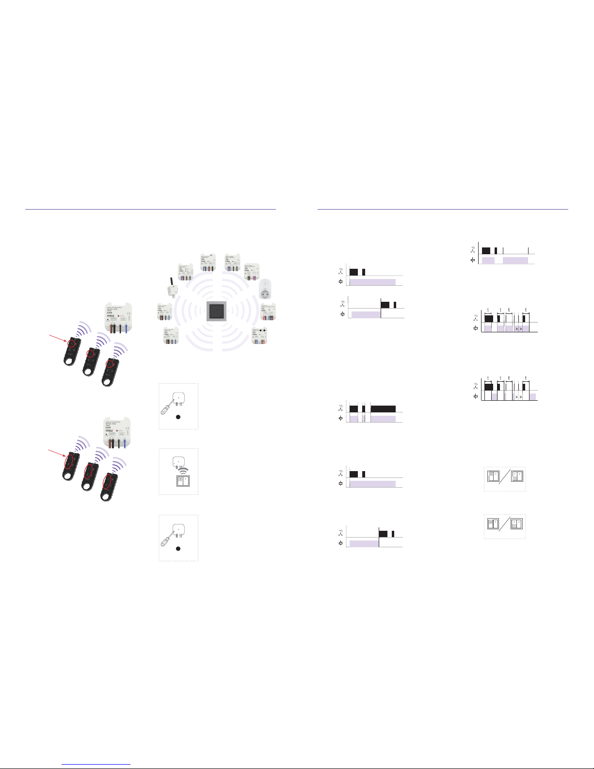
1. Assignment of transmitter controls
The entire setup can be divided into three levels:
Each switching, dimming, shutter component can be
controlled by a 32 channel controller (RF Key, RFWB20/40 RFIM-20/40 RFSG-1M). When one channel
represents a single button on the remote control.
5. SET DESIGN ELEMENTS WITH CONTROLLERS AND SYSTEM UNITS
... up to 32
controls
... up to 16
controls
1 channel = 1 but ton
to control
2 channels = 2 but tons
to control
Conversely, one channel controller can switch 10
components 10 This is used to command the scene.
The the deployment of components or unit is very
important, if you use a fob (which is portable), as the
command may not arrive at any of components and
the features of the scenes are not executed. Therefore, we would rather recommend the use of a wireless switch such as the RFWB a stable placed controller with perfectly visibility to the components.
How to do it:
• depress the programming button for less than 1 sec using an
appropriate tool to access the
programming mode
• after, by a number of presses
as indicated on the controller,
set the component function
• again depressing the programming button for less than 1 sec
to save the function settings
Page 12
<0.5s
<0.5s >0.5s >0.5s
<0.5s
<0.5s >0.5s
<0.5s
a b c
<0.5s
<0.5s >0.5s >0.5s
<0.5s
<0.5s >0.5s
<0.5s
a b c
t=3s
t=3s
t=3s
<3s
<3s >3s <3s >3s
<3s
<3s
a b c
3s
3s
<0.5s
<0.5s >0.5s >0.5s
<0.5s
<0.5s >0.5s
<0.5s
a b c
t=3s
t=3s
<0.5s >0.5s
<0.5s
<0.5s >0.5s
<0.5s
<0.5s
<0.5s
t=2s..30min
<0.5s
t=2s..30min
PROG
> 8s
1 x
PROG
> 5s
1 x
Installation manual iNELS RF Control22 23Installation manual iNELS RF Control
Multifunction
Function: Dimming component
Function lighting scene 3
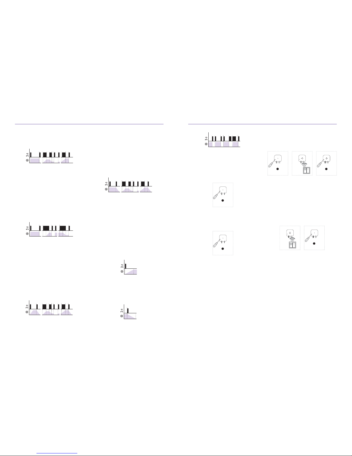
a) Press the programmed button for less than 0.5 sec-
onds to light continuously, it illuminates after 3 seconds (at 100% brightness) continuously. Another
short press and the light will switch o in 3 seconds.
Function lighting scene 2
a) Press the programmed button less than 3 seconds
the light goes on, press again it goes out.
b) To avoid undesirable brightness adjustment. To
adjust brightness press the programmed button
for more than 3 seconds. When you release the
button, the brightness level is stored in memory
and further short pressings switch on/o the light
to this intensity.
c) To avoid undesirable brightness adjustment. To
adjust brightness press the programmed button
for more than 3 seconds. When you release the
button, the brightness level is stored in memory
and further short pressings switch on/o the light
at this intensity.
Function lighting scene 1
a) Press the programmed button for less than 0.5
seconds to switch on light, press again, it goes out.
b) Press the programmed button for longer than 0.5
seconds to adjust brightness After the button is
released, light intensity is stored in memory and
further short pressings switch on/o the light at
this intensity.
c) It is possible to change the intensity at any time, to
readjust long press the programmed buttons The
component remembers the set brightness levels
even after the power is turned o .
Function ON/OFF
If the light is o , pressing the programmed button activates it. If the light is on, pressing the programmed button deactivates it.
Function Sun Set
After pressing the programmed button on the RF remote control the light starts dimming for a set period
of time ranging from 2 seconds to 30 minutes.
Function Sunrise
After pressing programmed button oon the RF remote
control lighting will light up for a set period of time
ranging from 2 seconds to 30 minutes.
Function lighting scene 4
a) Press the programmed button for less than 0.5
seconds to switch on the light Another short press
of the button and the light will switch o after
3 seconds (at 100% brightness).
b) Press programmed button for longer than 0.5
seconds to adjust brightness After the button is
released, light intensity is stored in memory and
further short pressings switch on/o the light at
this intensity.
c) Brightness may be adjusted at any time by press-
ing the programmed button.
The component remembers the set brightness levels
even after the power is turned o .
To Delete
If you want to delete an component from one channel
of the controller, depress the button on the controller (from baseline) for 5 seconds, followed by a short
press of the select button on the controller.
If you want to erase the component completely from
the memory of all controller channels, depress the
programming button for 8 seconds (until double fl ashing LED disappears), then short press programming
button to confi rm.
b) Press the programmed button for longer than 0.5
seconds to adjust brightness After the button is
released, light intensity is stored in memory and
further short pressings switch on/o the light at
this intensity.
c) The brightness may be adjusted at any time by
pressing the programmed component button The
set brightness levels are remembered even after
the power is turned o .
Time setting
In function of the switching components 5 and 6 with
dimmer function components sunrise / sunset.
1
PROG
> 1s
1 x
3
PROG
> 5s
1 x
2
5 (6) x
5
PROG
< 1s
1 x
t = 2s . . . 60min.
4
1 x
1. Press the programming button for 1 second on a
component; it is put into programming mode. LED
is fl ashing at one second intervals.
2. The desired function assignment is carried out 5
(6) - By pressing the selected button on the remote
control RF (delay between pressing must be 1s).
3. Press the programming button for longer than 5 seconds, indicating component into timing mode. 2x
LED fl ashes at one second intervals. After releasing
the button starts accumulating time.
4. After setting the desired time (ranging 2s ... 60min)
the timer operation is fi nished by pressing the
button on the RF remote control, which is assigned
to a function. This set time interval is stored in the
memory element.
5. Programming terminated by pressing the programming button on the element, for less than 1 second
(LED turns o ).
Page 13
+
-
30s
+
-
3s = 1 x
+
-
3s = 1 x
+
-
30s
+
-
1x
PROG
< 1s1 x
PROG
> 1s1 x
- 2s ... 60min.
PROG
> 5s1 x
Installation manual iNELS RF Control24 25Installation manual iNELS RF Control
005A95
007585
To add this address to the system controller assignment It is not necessary to do any operation with the
element.
Smart Box eLAN-RF can be set through your iOS or
Android but also via a web interface, which is used
mainly for system partners. This environment allows
you to download the project to the PC or uploaded
to eLAN.
Maximum load of the eLAN-RF system unit
- Max number of actuators - 40 (maximum of 70 (not
counting the heating circuits))
- Max number of timetables for actuators - 10
- Max number of timetables for heating - 16
- Max number of actuators in one timetable - 10
- Max number of intervals in one time schedule - 8
- Max number of heating circuits - 16
- Max number of actors in the heating system - 10
- Max number of central resources - 4
- Max number of circuits on a single central source - 16
Box Clever is factory preset to an automatic DHCP = if
you have a fi xed IP is necessary to change this,through
a web interface IP address eLAN just fi nd using a magnifying glass search press to fi nd eLAN network or
other software - IP scanner.
In our experience, it may happen that some browsers
do not load eLAN properly (in practice mainly Internet
Explorer), so use another, for example Google Chrome
Opera, Firefox...
Another system feature to understand - touch control
unit RF Touch, remote control with an OLED display
RF Pilot, smart RF box eLAN-RF or GSM gateway RFGSM-220M.
Each component is etched with a tvz. address (6-digit
unique code).
Be sure to use the installation manual, which presents
a list of the installation components It is part of the RF
Pilot and RF Touch manual.
2. Assigning a system component
box
socket
module
thermo-valve
It is a very similar level and one assignment takes
place via the multifunction switching components
RFSA-6x The detectors are distributed on-stage which could be a monostable motion detector or
a bistable door detector.
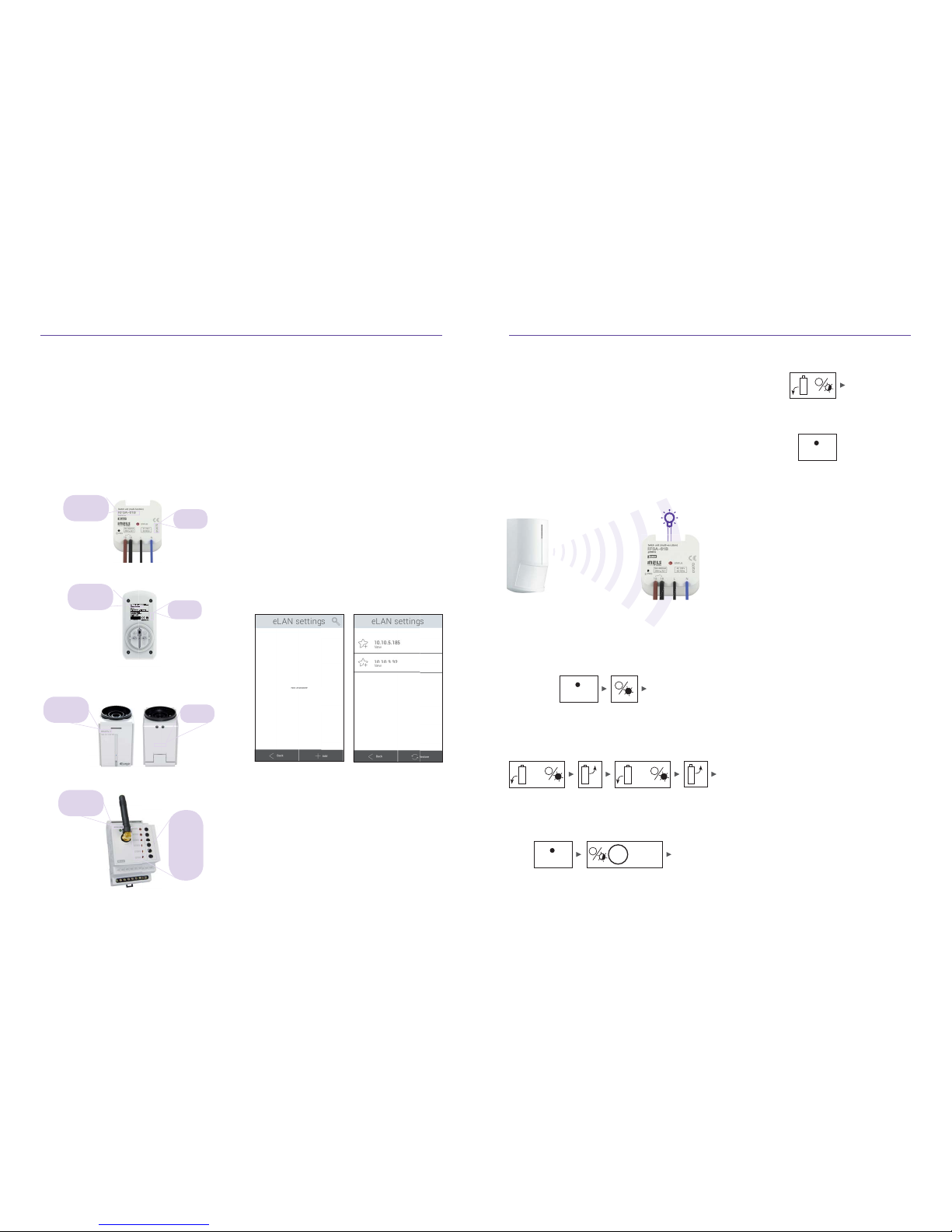
1. a monostable detector (motion), can use a two
functions impulse when it detects motion (suitable for activating GSM)
2. delay return after detection (ideal for automatic
lighting control)
3. Assignment of detectors (80 Jablotron - OASIS)
What to watch out for when joining various protocols
between each other (= intermediary between device
and smart phone).
Smart boxes themselves often have the logos of several standards, which indicates the compatibility of all
elements among themselves.
The opposite is true, because that the HUB may be
compatible with two of the thousands of equipment
communications standards. This signifi cantly reduces
compatibility with existing devices in the installation.
Often at times there is also the complaint of „the mutual compatibility“ but incompatibility within the function = of the components within one system, with all
the features (Eg Timing), but when connected to another system via HUB can only switch on and o .
How to do it:
• Holding down the button will bring programming
component to programming mode.
• Inserting the number of batteries defi nes the func-
tion (if you select 2).
• It is necessary to set the time (range 0-60min) and
hold programming button on the component for
5 seconds (then the load-time is automatically indicated by a double fl ash).
• Stop loading time performing again by inserting
the battery into the detector.
• Again press the programming button to save the
settings function.
Batteries are inserted and pulled from the detector
a total of 3 times. Deletion is performed in the same
manner as in section one.
Address:
00150A
Component
type:
RFSA-61B
Address:
005A95
Component
type:
RFSC-61/F
Address:
CF0X50
DF0X50
CF0X50
DF0X50
CF0X50
DF0X50
Component
type:
RFSA-66M
Address:
007585
Component
type:
RFATV-1
Page 14
iMM Client
Notebook
Internet
iMM Server
i
MM
Client
HDMI
HDMI
HDMI
HDMI
IR
IR
IR
Wi-Fi
Wi-Fi
I1
I2
I3
BUS
iHC-MAiHC-MI iHC-TAiHC-TI
GSM
Data
L1
L2
L3
TARIF
CT
PULS
PULS
IRS
MS
LS
PULS
IRS
PULS
PULS
PULS
TARIF
CIB (iNELS sběrnice)
NAS
USB
DISK
iHC-MAIR
RF
iHC-MIRF iHC-MARF
Installation manual iNELS RF Control26 27Installation manual iNELS RF Control
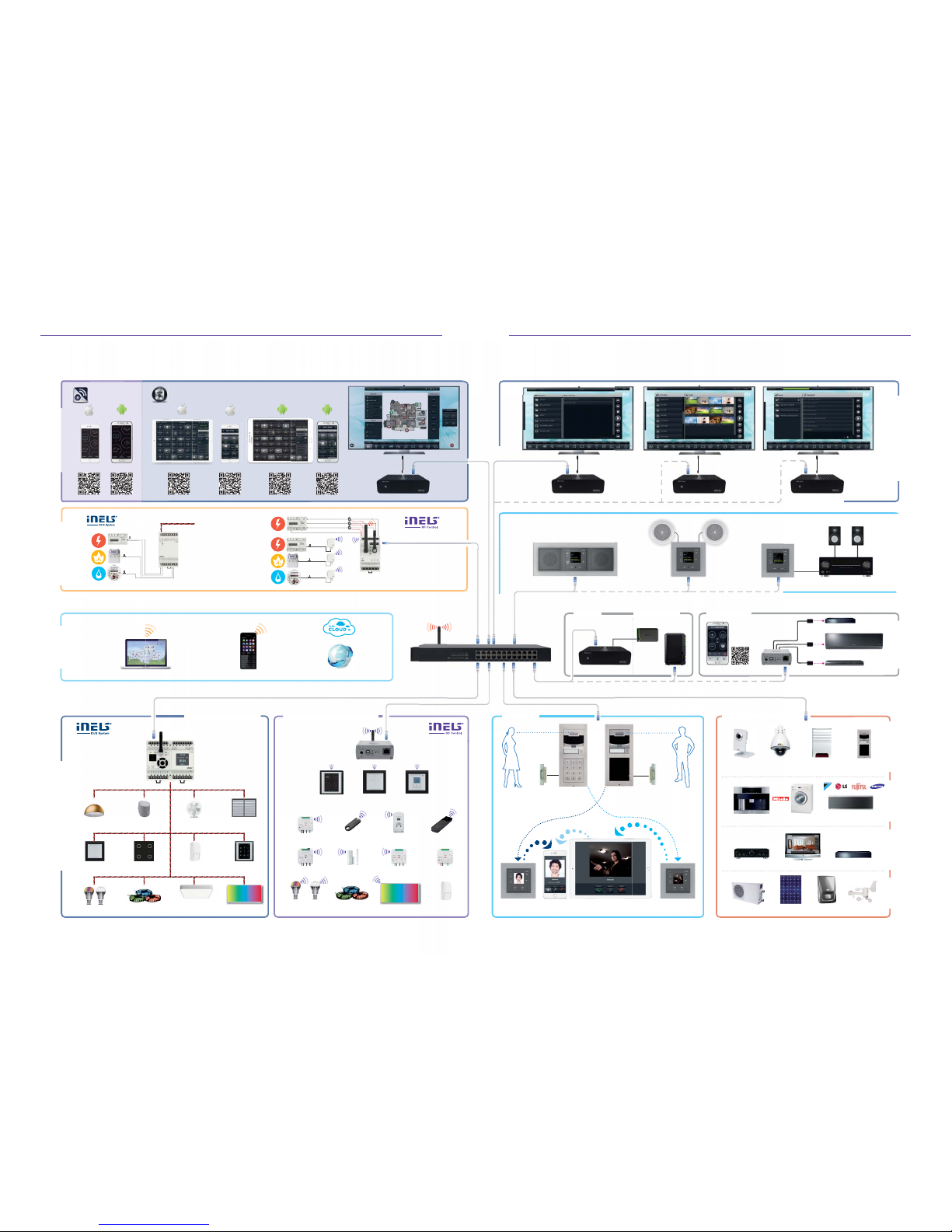
How to connect the BUS version of iNELS?
ELECTRICAL INSTALLATION
Lighting
control
Push
buttons
LED Lighting
dimming
Shutters
control
Touch
unit
DMX protocol
Switching
appliances
Detectors
DALI protocol
Temperature
regulation
Glass
controllers
RGB strips
RF Touch
Remote controller
Switching actuator
Heating actuator
RF RGB
bulb
RF LED
bulb
Push
buttons
Dimming actuator
Motion sensor
RGB stripes
Temperature
regulation
Shutter actuator
Door/Window
detector
RGB panel
WIRELESS INSTALLATIONS
RF Key Wireless socket
BUS INSTALLATIONS
Smart
RF Box
eLAN-RF-003
Central
unit
CU3-02M
INTERCOM
Weather stationBoilerHeating pump
Internal IP
camera
Solar panel
External IP
camera
Air Conditioning
Intercom
Washing machine,
Dryer
Co ee machine
TV Blu-ray
Security
system
Amplifi es
3
rd
DEVICES INTERGRATION
Intercom
Intercom
Door
lock
Door
lock
LARA Intercom iPhone iPad LARA Intercom
COMMUNICATION
HOME
APPLIANCES
AUDIO/VIDEO ENERGY
Switch with PoE
Wi-Fi router
IR CONTROLSERVER DATA STORAGE
AUDIO DISTRIBUTION IR CONTROLVIDEO DISTRIBUTION
Smart IR box
eLAN-IR-003
LARA
(Audiozone1)
iMM Client (Videozone 1) iMM Client (Videozone 3)
LARA
(Audiozone 2)
Amplifi er
... max 128 Audiozones
... max 128 Videozones
LARA
(Audiozone 3)
iMM Client (Videozone 2)
ENERGY
MEASUREMENT
EXTERNAL
CONTROL
Electricity ElectricityGas
GasWater
Electricity
Binary
input
IM3-140M
Energy gateway
RFPM-2M
APPLICATIONS
Water
Page 15
Erase DataFlash
1024/1024
Check DataFlash
0063/1024
00000304 1701FF35
Starting . . . OK
Init EEPROM . . . OK
Device . . . RFT W (0377)
Init RIC . . . OK
Init RF . . . OK (04)
Init DATA . . . ?????...
Init Program . . . E0110
Init for radio . . .
r6 v02.04
Installation manual iNELS RF Control28 29Installation manual iNELS RF Control
With two-way communication is confi rmed by feedback on the state of the element within the system
units (RF Pilot, Smart RF box eLAN ... RF Touch, RFGSM-220M).
switching (on/o )
dimming (on/o /brightness)
shutters (open/close)
temperature (switched on/o /mode/temperature)
monitoring (detection)
Infl uence/interference of two systems iNELS RF
Control installed next to each other is not possible
because of the use of a unique protocol RFIO.
iNELS RF Control Boxes are made of non-combustible material and UV inhibitors which prolongs their
lifespan.
In combination with the existing wiring can be installed iNELS RF Control products that have an „S“
(a classic button) RFSA-61B, RFDEL-71M, 71B RFDELHere the maximum line length is 10 m.
If there is a power failure (or the battery runs out)
When the power is restored it is not necessary to reprogram components After a power cycle, the state
of the components (which should be according to
the program) with the system controller carry out
a follow-up action.
It is recommended for interference voltage to install
RC members on components.
It is not recommended to install dimmers beside the
contacts.
In the event that you are installing two (or more)
control touch RF Touch units - use the sync function for the reason that you ensure equal status of
all elements.
It is not recommended to install iNELS RF Control
device for securing vital functions and also in industrial areas for operation (cranes, hoists ...) It is an environment with increased infl uence of interference.
For users of the system, there should be a di erence
of at least 1 second between the commands.
You can transfer data sending from one RF Pilot to
a second RF Pilot.
5.1 What else you should know when
you install
5.2 Camera compatibility
3. The cameras support M-JPEG
2. D-Link
1. AXIS
Camera model Video Type Zvuk
206(W) M-JPEG No
206M M-JPEG No
207M(W) M-JPEG MPEG-4 Yes
207W M-JPEG MPEG-4 Yes
209FD(-R) M-JPEG MPEG-4 No
209MFD(-R) M-JPEG MPEG-4 No
210 M-JPEG MPEG-4 No
.
.
.
Camera model Video Type Zvuk
DCS-2102/2121 M-JPEG No
DCS-2120 M-JPEG Yes
DCS-3410 M-JPEG No
DCS-700L M-JPEG Yes
DCS-900(A) M-JPEG No
DCS-900(B/B2) M-JPEG No
DCS-910/920 M-JPEG No
.
.
.
The following procedure uses equipment RFAF/USB,
which is the standard o ered by ELKO EP and which
is lent to system integrators.
Procedure for the update from version 2.23 to version 1.07x.
A condition of the migration is that the default fi rmware version in the RFT is at least 1.07 (or 1.07, b).
1. On the RF Touch screen click on the Clock ->
then on the „Settings“ -> enter the password
(default: 1111) -> press the „other“ -> press the
„down arrow“ -> press the „Update Software“
and click „enable“.
2. Open the application „RF_AF_USB_0_02“
checkmark and choose the right carrier frequency RF Touch (EU - 868.5 MHz, RU - 868.1 MHz,
USA - 915 MHz and AUS - 916 MHz).
3. In the application, Click “Open” from the directory folder to update RF Touch select “Boot” set
to the frequency:
„RFT_FW_boot_107_to_2x_EU.bin“
„RFT_FW_boot_107_to_2x_RU.bin“
„RFT_FW_boot_107_to_2x_USA.bin“
„RFT_FW_boot_107_to_2x_AUS.bin“
press “Start”
4. Now, select from the menu „SW updates“ and
reboot the entire device: In the „Settings“ menu,
press „Reset Device“, and then you just press
„OK“ (do not enter password, so as not to delete
the settings).
5. After rebooting is complete delete (erase) and
control (check) fl ash memory - counter to 2x 1024.
6. Once the test has completed (about 3.5 min)
and the RF Touch booted up to „white screen“
-> then disconnect the power and then reconnect to the RF Touch.
7. Now the screen begins to accrue data , where it
is already runs a listing of statuses and checking
the HW RF Touch. When the last line is load-
6. BACKUP/UPDATE UNITS, RF TOUCH OR RF PILOT
ing “wait for...“. Put your fi nger in the upper right
corner of the display, until the last line of the
statement shows „wait for radio“.
8. It is now possible to load any remaining fi les
Again in Click „Open“ and choose a fi le from the
folder to update RF Touch. It does not matter in
what order, but no one can be missed!
„RFT_BLK_grafi ka_black_v206.bin“
„RFT_BLU_grafi ka_blue_v206.bin“
„RFT_FW_v206.bin“
„RFT_FW2_v204.bin“
„RFT_GRE_grafi ka_green_v206.bin“
„RFT_MGN_grafi ka_magenta_v206.bin“
9. After uploading all fi les (each fi le about 2 min At
an e ciency of 98%) once again disconnected
the RF Touch from power RF Touch will remember its settings, there is no loss settings.
10. Connect the power supply -> after booting the
RF Touch screen click on the Clock -> then in the
upper left corner on the „Info“ -> FW: 2.23.
Page 16
Installation manual iNELS RF Control30 31Installation manual iNELS RF Control
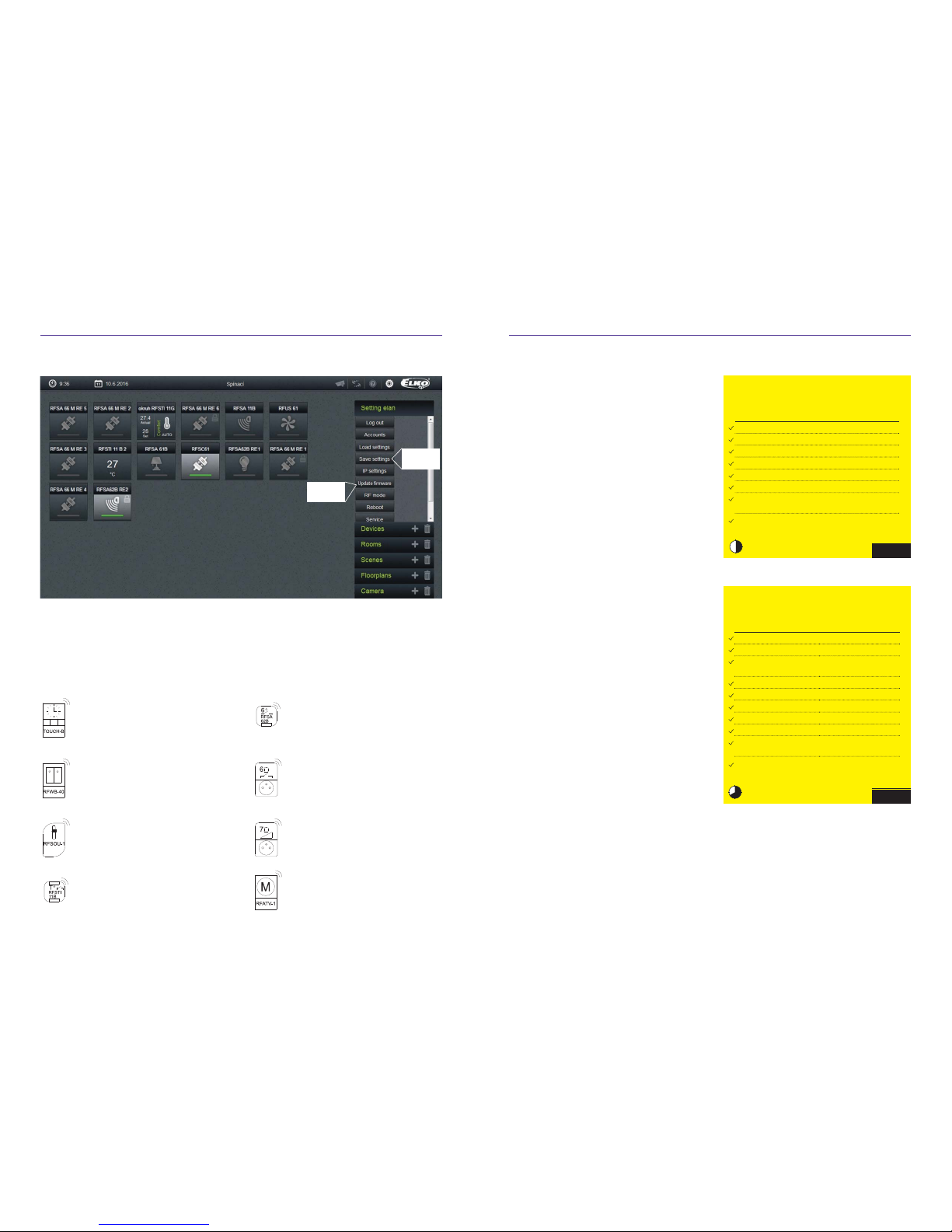
6.1 Backup parameters/update units eLAN-RF
Project Support
Database of brands can be found here:
http://www.elkoep.cz/podpora/podpora-projekce/knihovnyznaek/
Examples of Branding Used
RF Touch-B
Touch control unit KU
RFWB-40/G
Wireless 2-button control
RFSOU-1
Wireless twilight switch, IP65
RFSTI-11B
Switching component with temperature sensor - built-in
RFSA-62B
Switching wireless device two channels,
6 functions, built-in
RFSC-61
Multifunction switch socket
(6 functions)
RFDSC-71
Multifunction Dimmer Socket
(7 Functions)
RFATV-1
Wireless thermo-valve
6.2 Did you know that...
• RF Pilot can group RFDA-73/RGB components under one control panel? It can operate more than 100 m RGB LED strips from
one control window.
• The operations of the Smart RF box (eLANRF...) (controlled via smartphone) works
without an Internet connection.
• RF Pilot shows the status of the commands:
green tick - command is executed,
red cross - the command is not exercised,
orange tick - command is partially executed - When in one of the scenes and at
least one of the eight commands has been
performed. This can happen if the RF Pilot
moving around and trying to control components e.g. moving from garden to house.
• RF LED bulbs white or RGB are controllable
from a wireless controller and a switch in
the current installation.
• Under one RF Touch command control unit
up to 20 components can be assigned.
these can be stored in up to 10 „Scenes“.
• Wireless switches are available in 36 frame
designs (glass, wood, metal, stone...).
• When installing components RFDA-73/
RGB (RGB strip) or RF RGB LED and subsequently controlling by RF KEY or wireless
switch RFWB-40 - pressing channel 3 and
then 2 activates the automatic blending of
colors (in iHC-MARF/MIRF - Circus mode).
• In the event you want to wirelessly dim
2 KW (AC1) the solution is to connect the
analog component RFDAC-71B Control Terminals (0-10V) to the dimmer DIM-6.
• For control via Smart RF box a tablet can
also be used (size can not exceed 7“).
• It is true that one „scene“ can have up to 20
commands.
Installation price example:
Apartment
22 745,-
Functionality Product Type
Price
(CZK)
heater control (2 zones) 2 x RFSTI-11B
3158,-
lighting control (4) 4 x RFDEL-71B
6176,-
awning 1 x RFSA-61B
1113,-
appliance socket control 1 x RFSA-66M
2802,-
door detector 1 x RFWD-100
980,-
wireless switch 2 x RFWB-40
1592,-
RF remote control with an
OLED RF Pilot display
1 x RF Pilot
2814,-
control via smartphone,
tablets (smart box)
1 x eLAN-RF-003
4110,-
installation time 6 hours
House
34 410,-
Functionality Product type Price
(CZK)
heating control (zone 3) 3 x
RFSTI-11B 4737,-
shutters (2) 2 x RFJA-12B 2816,-
light control
(Including dimming)
4 x
RFDEL-71B 6176,-
RGB LED strip control 1 x
RFDA-73/RGB 2050,-
appliance socket control 1 x
RFSA-66M 2802,-
irrigation operation 1 x
RFSA-61B 1113,-
windows open detector 2 x
RFWD-100 1840,-
wireless switch 2 x
RFWB-40 1592,-
control by RF Touch
(Central touch unit)
1 x RF Touch/W 7174,-
control via smartphone,
tablets (smart box)
1 x eLAN-RF-003
4110,-
installation time only 1 working day
update
fi rmware
advance
project
Page 17
RF T o uch-W
RFDA-71B
RFDA- 71B
RFDA- 71B
RFDA-11B
RFDA-11B
RFSA-61B
RFSA-6 1B
RFSA-61B
RFSA-11BRFSA-11B
RFSA-1 1B
RFSA-1 1B
RFSA-11B
RFJA-12B/230V
RFJA-12B/230V
RFJA-1 2B/ 23 0V
RFJA -12B /230V
RFJA-12B/230V
RFJA-12B/230V
RFJA-12B/230V
RFJA-1 2B/ 230 V
RFSTI-11B
RFSTI- 11B
RFSTI -11/G
RFSTI -11 /G
RFSTI-11/G
RFSTI -11 /G
RFSA-61B
RFSA-61B
RFDAC-71B
RFDAC-71B
RFJA-12B/230V
RFJA-12B/230V
RFJA-12B/230V
RFJA-12B/230V
RFSA-11B
RFSA-11B
RF Touch-W
RFSTI-11B
RFTI-10B
RFSA-11B/RFSA-61B
RF Touch
RFJA-12B/230V
RFSTI-11B
RFTI-11/G
RFDA-71B
RFWB-40/G
RFWB-20/G
RFSA-11B/RFSA-61B
RF Touch
RFJA-12B/230V
RFSTI-11B
RFTI-10B
RFDA-71B
RFWB-40/G
RFWB-20/G
RFSA-61B
RF Touch
RFJA-12B/230V
RFSTI-11B
RFWB-40/G
RFWB-20/G
Installation manual iNELS RF Control32 33Installation manual iNELS RF Control
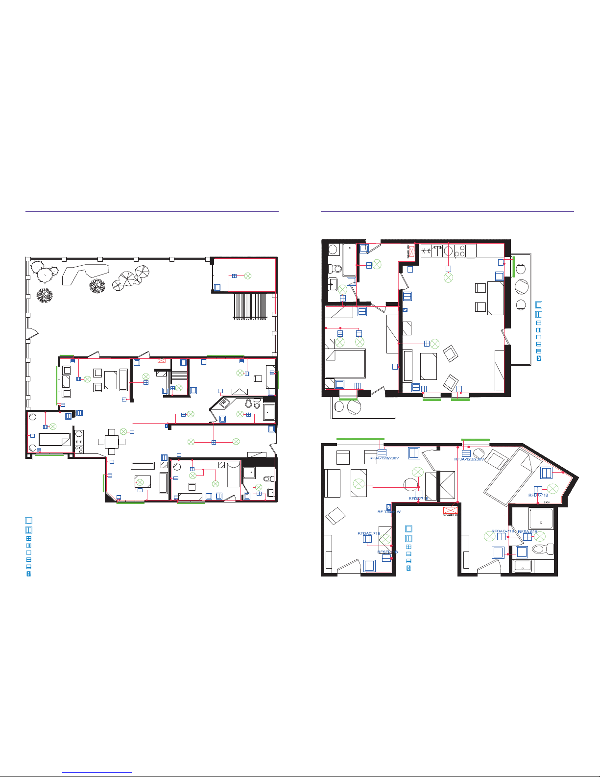
Examples in CAD (drawing) house, apartment, hotel room.
Family Home RF Control
Flat/Apartment RF Control
Legend:
Legend:
Legend:
Hotel Guest Room RF Control
Page 18
Installation manual iNELS RF Control34 35Installation manual iNELS RF Control
• Comprehensive system = no need to buy
components from di erent manufacturers.
In the event that such components are required this increases the cost of purchase.
• Everything is 100% compatible with each
other = one communication (RF Control). In
the event you have a “smart box” with multiple protocols (Zwave, ZigBee, EnOcean...)
This does not mean that all the components
are compatible with each other - it depends
on the “API” of the product that is implemented in the “smart box”.
• Communication frequencies for building automation - the best results in communication.
• Bi-directional communication.
• Switches and dimmers can be connected to
the existing button.
• System settings are possible without a PC.
• Application for SMART TV, SMART Watch
Smasung gear S2.
• iNELS RF has components with higher
loads, e.g. switching component with contact Tyco Electronics - 16A = 4000W (AgSnO material - for switching L, C load).
• Dimmers are universal using a light source
with adjustable minimum brightness.
• All versions of iNELS RF Control are compatible with each other = from 2009 and
beyond.
• Component housing does not contained
combustible material and o ers UV protection.
• The ability of measuring the quality of the
signal between the controller and the component.
• Update - fl ash KEY RFAF/USB to update
software.
• You can gradually add to the system, starting
with just one controller and one component.
• Compatibility with BUS system.
• Customer tailored solutions (hotels, hostels).
• Online technical support - system partners
have a single personal contact.
• Own production and development.
• The policy stipulates di erent sales discounts
for system partners = end users do not get
the same price. The idea of selling price of the
7. WHY SELL INELS RF CONTROL
installation is that of the system partner (or
the user starts with Smart sets) SP Service,
other products are added to the SP.
• Support with exhibitions, demo cases, panels and training.
• iNELS RF Control system is not a toy.
• No license fees or other costs for sw (or applications).
• We did not minimize products to the detriment of less resistance.
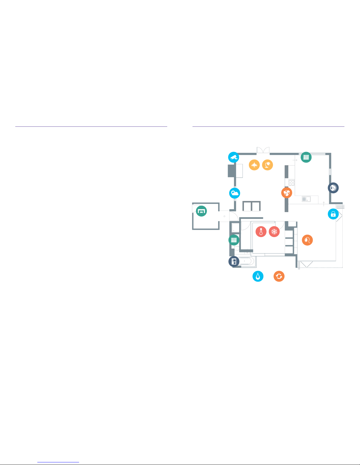
8. WHAT CAN YOU CONTROL?
Blinds and shutters
Actuators allow t he control of
various typ es of shading. It is
possible to set t he time, modes,
scenes or contro l manually.
Heating and
Air Conditioning
iNELS allows you to c ontrol up to 40
independent HVAC or heating circuits. Set in seve ral ways: RF Touch,
a smart phon e or a thermostat.
Scenes
With one button o f the controller you ca n
instant contro l of multiple devices ( light
scenes, everything o , nocturn al corridor,...).
Weath er
When it‘s blowing,
blinds are clo sed.
Lighting
Simple switch ing or dimming of
various typ es of light sources ,
including L EDs, even RGB color.
Macro functiona lity
Blinds contro l by light intensity.
Appliances
Switching accord ing to the selected
applicatio n mode or manuall y by
any control system .
Garage, gate
Can be operate d by the
driver or automa tically by
position when approaching.
Cameras
Through phon e applications
or RF Touch can view th e
images of up to ni ne cameras.
Irrigation
The system has a p redefi ned time mod e for
irrigation d epending on temp erature and
humidity. Ca n be operated man ually form
the application.
Extractors
Dependin g on presence or by
timer mode .
Energy measurement
Measures th e consumption of
electricit y, water and gas which
are wirelessl y transmitted to the
Cloud, which provides information
to applicatio ns or PC browsers.
Security
The system inc ludes detectors
(Movement of th e window,
door, smoke), which are t he
foundation o f the home alarm.
Senses water leaks, warns of
fl ooding in the bat hroom
or sink overfl ow.
Door communicator
Verbal commun ication with the
guest and im ages via RF Touch
or phone applications.
Page 19
Installation manual iNELS RF Control36 37Installation manual iNELS RF Control
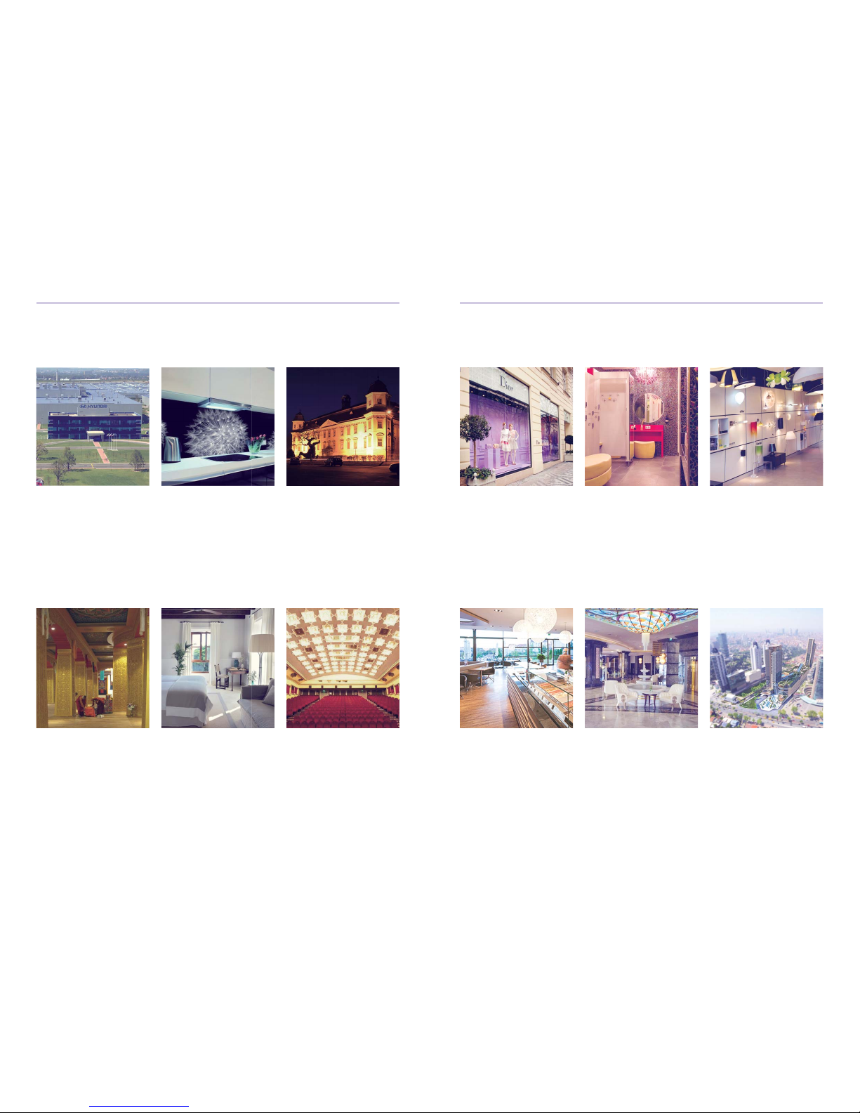
Wyndham Grand
• more than 3000 lighting circuits
are controlled through the DALI
protocol
• another thousand lighting circuits
are controlled via DA3-22M unit s
• the brain of the whole installation is
the central unit - CU3- 01M
Istanbul, Turkey
Wellness Chateau
• iNELS system controls:
- 47 dimmable light circuits,
- 63 switching light circuits
• control lighting SPA, swimming
pools, ceramic lo ungers
Petrovice, Czech Republic
Shop Dior
• hardware: RF Control
• channel multifunction dimmin g
actuator RFDA-71B
• single channel actuator with analog
output RFDAC-7 1B
• RF remote control Pilot
Praha, Czech Republic
Showroom Smart Light
• the entire building, including
warehouse and ex terior spaces ,
is controlled by iNELS intellige nt
electro-installation
• iNELS system controls:
- 15 switching light circuits,
- 5 dimmable light circuits ,
- 1 LED RGB light circuits , etc.
Bratislava, Slovakia
Sweet-shop Harrer
• all lights in the building are
managed by iNEL S system
• the sys tem is controlled by central u nit
CU2-01M, it was programmed in IDM
• iNELS BUS System:
- 6 dimming circuits,
- 20 switching circuits
Soproň, Hungary
Hotel Merit Premium
• all rooms are equipped with smart
electro-installation
• this is controlled by RFSA units
that switch set modes
• when designing a system, the
emphasis was placed o n the central
function (MAS TER switch)
Kyre nia , Cypr us
Since creating the i NELS system we per formed more tha n 5,000 installa tions.
9. iNELS REFERENCES
Cinema Corvin
• 6 movie theaters
• DALI control LED matrix
(800 lig hting fi xtures)
• projection scenes
• heating and A/C control
Budapest, Hungary
Chateau
• control (switch/dimm) of interior
lighting
• touch p anels
• fi re alarm system s
Holešov, Czech Republic
Hyundai
• 736 pcs LED High Bay within
retrofi tted lighting
• central control DALI ballast via
EDMC
• control of each zone from the
touch panel via app
Nošovice, Czech Republic
Promeko
• 27 apartments, 4 commercial
• heating, shutters, HVAC control
• video door-phone, intercom
• motion detectors and automatic
light intensity in the commu nal
areas
Olomouc, Czech Republic
Buddha Palace
• lighting control of historical interior
sections
• scenes light according to visitor
presence
• security system
Bhutan, India
Cal Reiet Santanyi
• swimming pool technology control
• fountain control
• Guest Room Hotel Manageme nt
System
Mallorca, Spain
Page 20
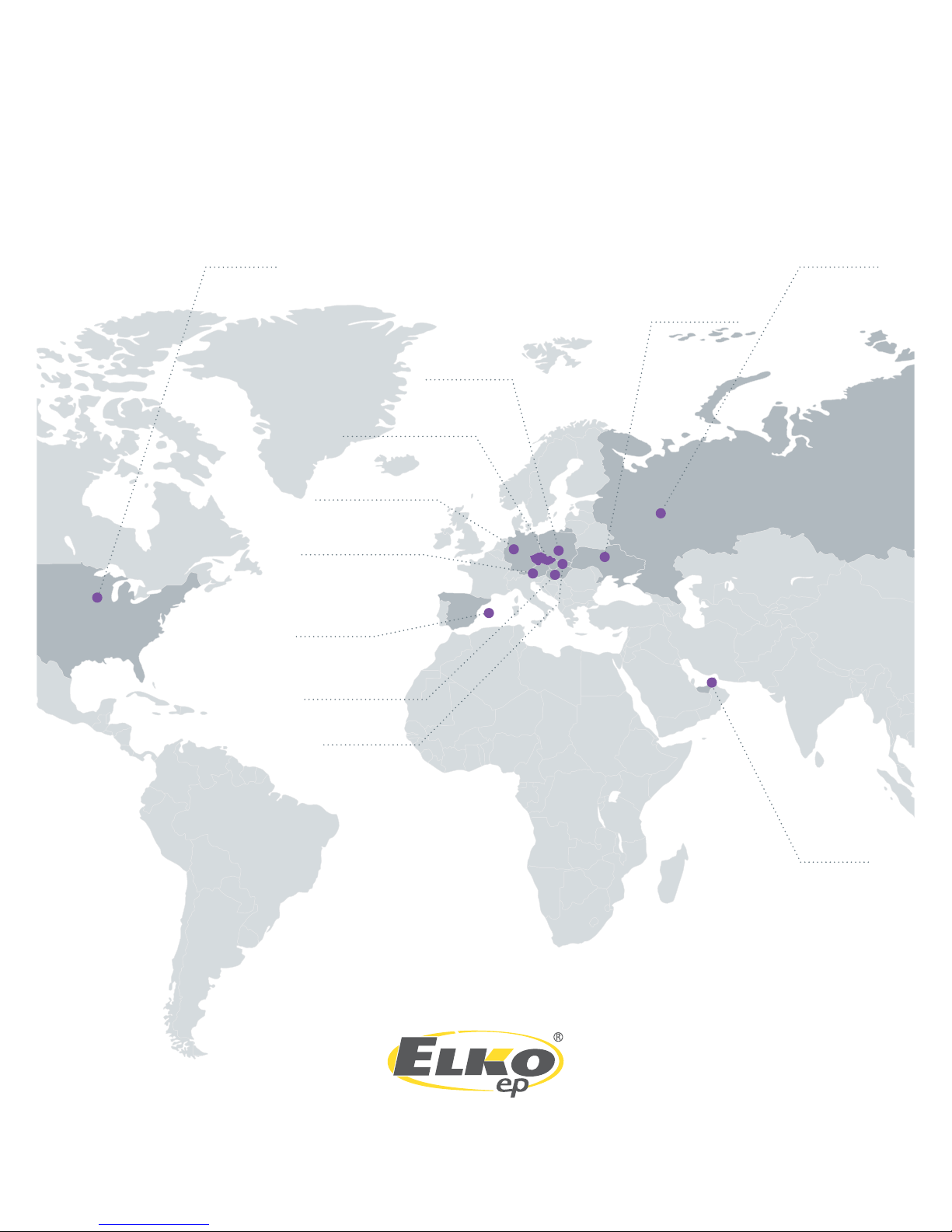
ELKO EP Holding
www.elkoep.com
rev.1
Russia
UAE
Spain
Germany
Czech Republic
Poland
Ukraine
Austria
Hungary
Slovakia
USA
 Loading...