

Page 1
IDRT3-1
1/2
1 4
2
3
+
-
BUS
BUS
Digital room thermo-controller
EN
Characteristics
- IDRT3-1 is a digital wa ll temperature controller used to reg ulate the temperature in a room.
- Using the IDRT3 -1, it is possible to correc t the given heating / cooling c ircuit within a range of ±3, ±4
or ±5 °C (optional in SW iDM3).
- The temperature controller is equipped with an integrated heat sensor used to measure the room
temperature. It is also equipped with two analog digital inputs (AIN/DIN), which can be used
to connect t wo potential f ree contacts or a single external temperature sensor TC/TZ (e.g. for
measuring the fl oor temperature).
- The display shows t he current temperature and af ter pressing one of two but tons under the display,
you can control the d esired temperature.
- Readabilit y improves after pressing one of the buttons to a ctivate the backlight.
- Heating / coolin g circuit is assigned with a therm o-regulator using iDM3.
- In the case of temp erature correction wit hin ±3, ±4 or ± 5 °C, this change is valid until th e next time
mark within the t ime schedule establishe d in iDM3.
- IDRT3 -1 in design LOGUS
90
is intended for mounting into an inst allation box.
General instrucions
EXAMPLE MODEL OF CONTROL, ALL FUNCTIONS ARE FULLY PROGRAMMABLE
HOW TO CONTROL THE DEVICE
Buttons
^
^
can be set to required temperature in a room (of the given temperature circuit)
within the framework of the set correction range of ±3, ±4 or ±5 °C.
Activity of the heating circuit is indicated on the display by the ON symbol. In case red LED in a right
upper corner shines, the assigned heating circuit is active and the heating source is in operation. Each
heating circuit operate according to a temperature set in the iDM3 program (day and night, weekend
program, etc) in the software iDM3. If the display is symbol MAN, the heating circuit constantly heats
at a manually corrected temperature (correction is valid until the next time mark of the set program).
CONNECTION INTO THE SYSTEM
Connect the product to the system according to the connection diagram listed with each product.
The wires of data BUS of iNELS system are connected to the terminals BUS+ (standard red wire for
single-pair wiring, red and yellow for two-pair wiring) and BUS- (standard black wire for singlepair wiring, black and white for two-pair wiring), and it is not possible to change the terminals. A
twisted pair of wires must be used for the data BUS with a wire diameter at least 0.8 mm. Data
communications and power supply to the units are led in a single pair of wires, and you must observe
the power cable size with regard to voltage loss on the wire and the maximum power draw.
CAPACITY AND CENTRAL UNIT
It is possible to connect to the central unit CU3-01M or CU3-02M two independent BUSes by means
of terminals BUS1+, BUS1- and BUS2+, BUS2-. It is possible to connect to each BUS up to 32 units, so
it is possible to connect directly to the central unit a total of 64 units. It is necessary to comply with
the requirement of a maximum load of one BUS line - maximum up to 1000 mA current. It is the sum
of the rated currents of the units connected to the BUS line, other units can be connected using the
units MI3-02M, which generate further BUSes. These are connected to the CU3 unit via the system
BUS EBM and you can connect a total of 8 units via EBM BUS to the central unit MI3-02M.
COMMUNICATION BUS OF THE SYSTEM
The BUS must have a cable created by a twisted pair of wires for data BUS of the system with a
minimum wire diameter of 0.8 mm. A shielded cable must be used in case of installation of cables of
the BUS in an environment with the possibility of electromagnetic interference (e.g. when running
along power lines, near electric machines and devices, during LV passage through a distributor, etc.).
We highly recommend using the cable JYSTY 2x2x0.8 for BUS. The BUS cable is installed in accordance
with its mechanical properties given by the producer (into a pipe/bar, under plaster, underground,
suspended, etc.) To increase the mechanical resistance of cables, we always recommend installing
the cable into an electrical insulation pipe of the appropriate diameter. The total length of wires of
the BUS for CU3-01M (CU3-02M), or MI3-02M, can be 1100 m (550 m for each BUS). The topology
of the communications BUS is open with the exception of topology of the circuit. It is necessary
to use the cable FTP CAT5e or higher for the system BUS EBM - one pair of wires is connected to
the terminals EBM+ and EBM- and the second pair of wires can be curled and connected to GND
terminal (just on the one side of EBM BUS). The typology of EBM system BUS is strictly linear and must
be terminated at both ends with a nominal resistance value of 120 Ω. It is the installer‘s responsibility
to follow all instructions in the manual and all installation requirements for the RS485 BUS.
SUPPLYING THE SYSTEM
For supplying power to system units, it is possible to use the power sources of ELKO EP titled PS3100/iNELS. We recommend backing up the system with backup batteries connected to the source of
PS3-100/iNELS (see sample diagram of connecting the control system).
GENERAL INFORMATION
To operate the unit, it is necessary that the unit is connected to a central unit CU3 series, or to a
system that already contains this unit as its expansion to include further system.
All unit parameters are set through the central unit CU3-01M in the software iDM3.
There is LED diode on the PCB for indication of supply voltage and communication with the
central unit series CU3. In case that the RUN diode fl ashes at regular intervals, so there is standard
communication between the unit and BUS. If the RUN diode lights permanently, so the unit is
supplied from BUS, but there is no communication between BUS and unit. In case that RUN diode is
OFF, so there is no supply voltage on the terminals BUS+ and BUS-.
Connection
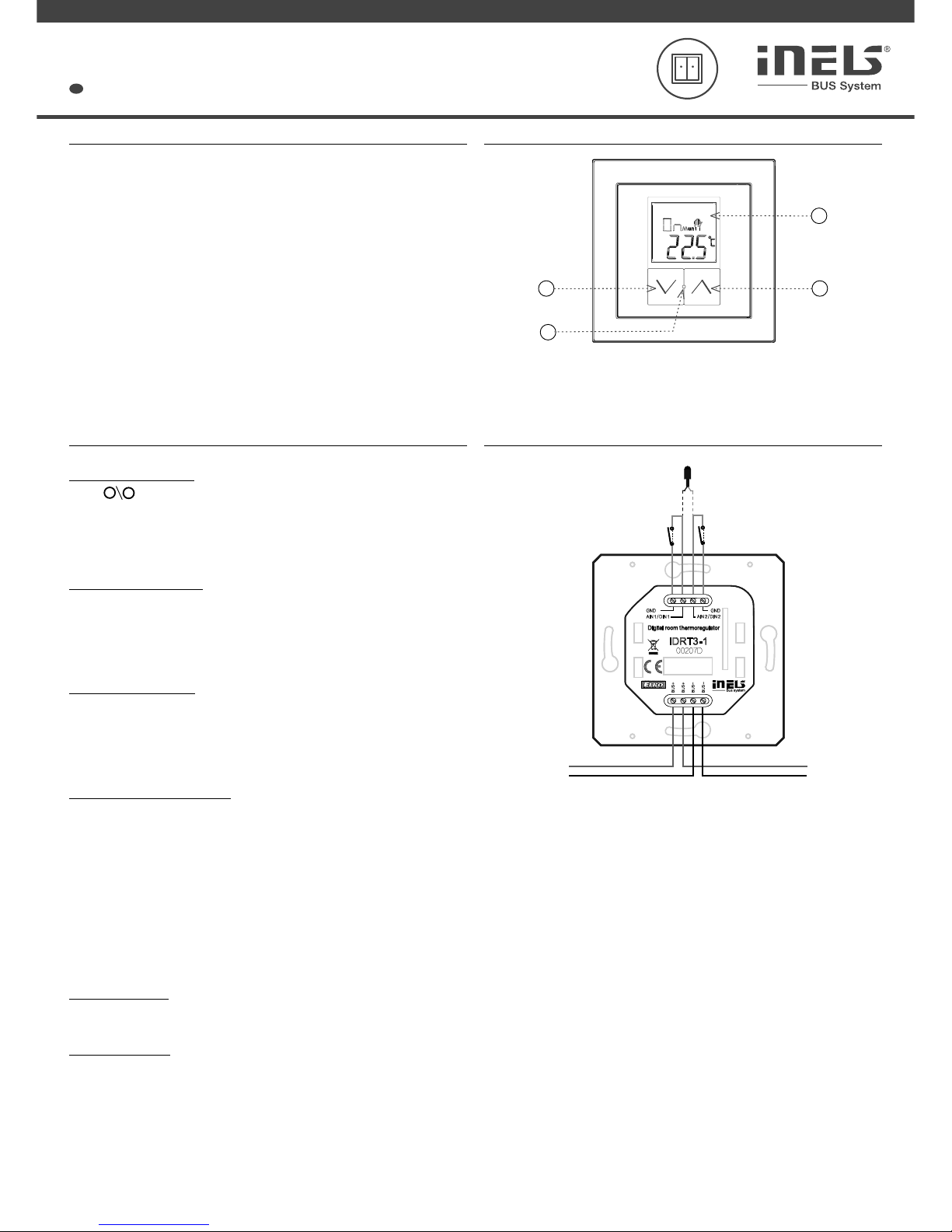
Description of device
1. Button to lower temperature
2. LED indication
3. Display
4. Button to rise temperature
Thermal sensors TC / TZ or *
2x input for fl oating contacts
(buttons, PIR etc.).
* The choice is made in iDM3 for each unit separately.
Page 2
02-86/2017
Rev.0
2/2
IDRT3-1
ELKO EP, s.r.o. | Palackého 493 | 769 01 Holešov, Všetuly | Czech republic | e-mail: [email protected]
TECHNICAL SUPPORT | E-mail: [email protected] | Mobil: +420 778 427 366 | Tel.: +420 573 514 276, +420 573 514 211 | Fax: +420 573 514 227 | www.inels.com
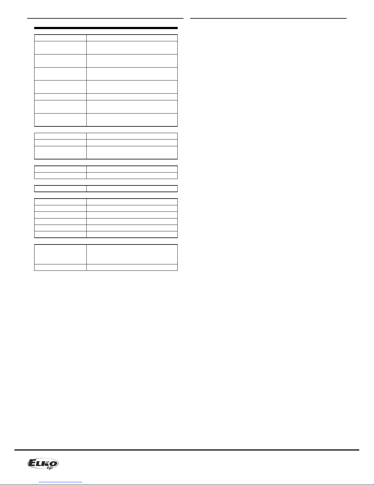
Technical parameters
Inputs
Temperature measuring:
Range / accuracy of
temp. measuring:
Heating / cooling circuit
correcti on:
Manual ontro l of heating /
cooling circu it:
External te mperature sensor:
Type external sens or:
Temperature measurement
range:
Temperature measurement
accuracy:
Communication
Installation:
Display:
Backlight:
Power supply
Supply voltage / tolerance:
Rated current:
Connection
Terminals:
Operating conditions
Operating temperature:
Protection degree:
Overvolt age category:
Pollution d egree:
Operation position:
Installation:
Dimensions and weight
Dimensions
- plastic:
- metal, glass , wood, granite:
Weight :
Warning
Before the device is installed and operated, read this instruc tion manual carefully and with full
understanding and Installation Guide System iNELS3. The instruction manual is designate d for
mounting the device and for the us er of such device. It has to be attached to elec tro-installation
documentati on. The instruc tion manual can be also fou nd on a web site www.inels .com. Attention,
dan ger o f inj ury by el ect rica l cur rent ! Mou ntin g and conn ect ion c an be done only by a p rofe ssio nal
with an adequate electrical qualifi cation, and all has to be done while obser ving valid regulations.
Do not touch par ts of the device that are energized. Danger of life-threat! While mounting,
servicing, executing any changes, and repairing it is essential to obs erve safety regulations, norms,
directives and special regulations for working with elec trical equipment. Before you start working
with the device, it is essential to have all wires, connected par ts, and ter minals de- energized. This
instruction manual contains only general directions which need to be applied in a particular
installation. In the course of inspections and maintenance, always check (while de-energized) if
terminals are tightened.
YES, built-in th ermo sensor
0 .. +55 °C;
0.3 °C from range
±3, ±4 or ±5°C
2x buttons
YES, the conn ection betwee n
AIN1/DIN1 and AIN2/DIN2
TC/T Z
-20 °C .. +120 °C
0.5°C from r ange
BUS
symbol display
YES
27 V DC, -20 / +10 %
20 mA (at 27V DC), from BUS
0.5 - 1 mm
2
0 .. +50 °C
IP20
II.
2
vertical, d ownward with BUS terminal
into installation box
85.6 x 85.6 x 50 mm
94 x 94 x 50 mm
73 g (without frame)
 Loading...