

Page 1
CU3-01M, CU3-02M
1/3
1
4
5
6
2
3
7
8
12
14
13
11
10
9
EN
Central unit
Characteristics
- CU3-01M and CU3-02M are central units’ of the iNELS system and mediators, bet ween user software interface and controllers, units and ac tuators connected to the BUS.
- It‘s possible to directly connect up to 2 lines of BUSes in to CU3-01M and CU3-02M, and on each BUS we can connect up to 32 iNELS3 units.
- The main diff erence between CU3- 02M and CU3- 01M is that CU3-02M is moreover equipped by RF module which enables communication with selected units from iNELS RF Control system.
- Central units CU -01M (02M) suppor t also peripheral units f rom iNELS2 thanks to external master MI3- 02M/ iNELS2.
- User´s project and retentive data are stored in a non-volatile internal memor y hereby data are backed up without the supply voltage. Real time clock (RTC) backup for 10 days.
- Power supply controlling system - network voltage and the status of the backup battery.
- Possibility of setting time synchronization via NTP server.
- The RJ45 Ethernet port‘s connec tor is located on the front panel of the unit, the transmission speed is 100 Mbps.
- For CU3-01M (02M) it is possible to use 4 potential-free inputs for conne cting external controllers (but tons, switches, sensors, detectors, etc.) and 2 analog inputs 0 - 30V.
- CU3-01M (02M) comes with OLED display that shows the current status and enables set tings (network settings, date, time, service) of the central unit CU3-01M (02M).
- Movement in the menu CU3-01M (02M) using arrows on the front panel.
- CU3-01M (02M) in 6-MODULE are designed for mounting into a switchboard on the EN60715 DIN rail.
Installation BUS:
-
Two-wired BUS with an arbitrar y topology (not only to be as closed circle).
-
With its own modulated communications on the DC voltage supply.
-
One line of BUS allows you to connect up max. 32 units of iNELS3, or iNELS2 if you use external mas ter MI3-02M/iNELS2.
-
The current load of one line is max. 1A.
- M
aximum length of the BUS is approximately 550 m (depends on the voltage drop).
-
Recommended cable:
- iNELS BUS Cable - Twisted pair of copper wires with size of AWG20 wire (diameter of 0.812 mm, cross-section of 0.5190 mm
2
).
System BUS EBM:
-
Used to connec t the CU3-01M(02M) central unit with MI3- 02M ex ternal masters, MI3-02M/iNELS2, GSM communicator GSM3- 01M or converter DALI/DMX EMDC-64M.
-
EBM has stric tly linear topology and wires are connec ted to terminals EBM + and EBM-, wires can not be interchanged.
-
Max. length of the line of BUS is 500 m.
-
The EBM BUS has to be terminated at both ends.
-
This part adapted to be inserted between terminals is included into central units packages and it is necessary to insert between terminals EBM+ and EBM-.
-
Reccomended cabling:
- CAT5e UTP and higher, or FTP CAT5e and higher or STP CAT5e and higher.
-
The confi gurat ions of units and the whole s ystem are done via Etherne t, through confi guration sof tware - iNELS3 Designer & M anager (iDM3), which is designed for operating sys tems Windows 7, Windows
8 and Windows 10.
-
The central unit features two communication protocols:
- ELKONET - to communicate with iMM and Connection Server or directly with the application iHC.
- ASCII - communication with third systems and integration with BMS (Building Management Systems), for example Niagara 4.
-
Supported Software:
- Parameteriz ation, confi guration, control and visualization:
iNELS3 Designer & Manager (iDM3).
-
By means of iDM3, you can update fi rmware of central units and p eripheral units connected by BUS.
Description of device
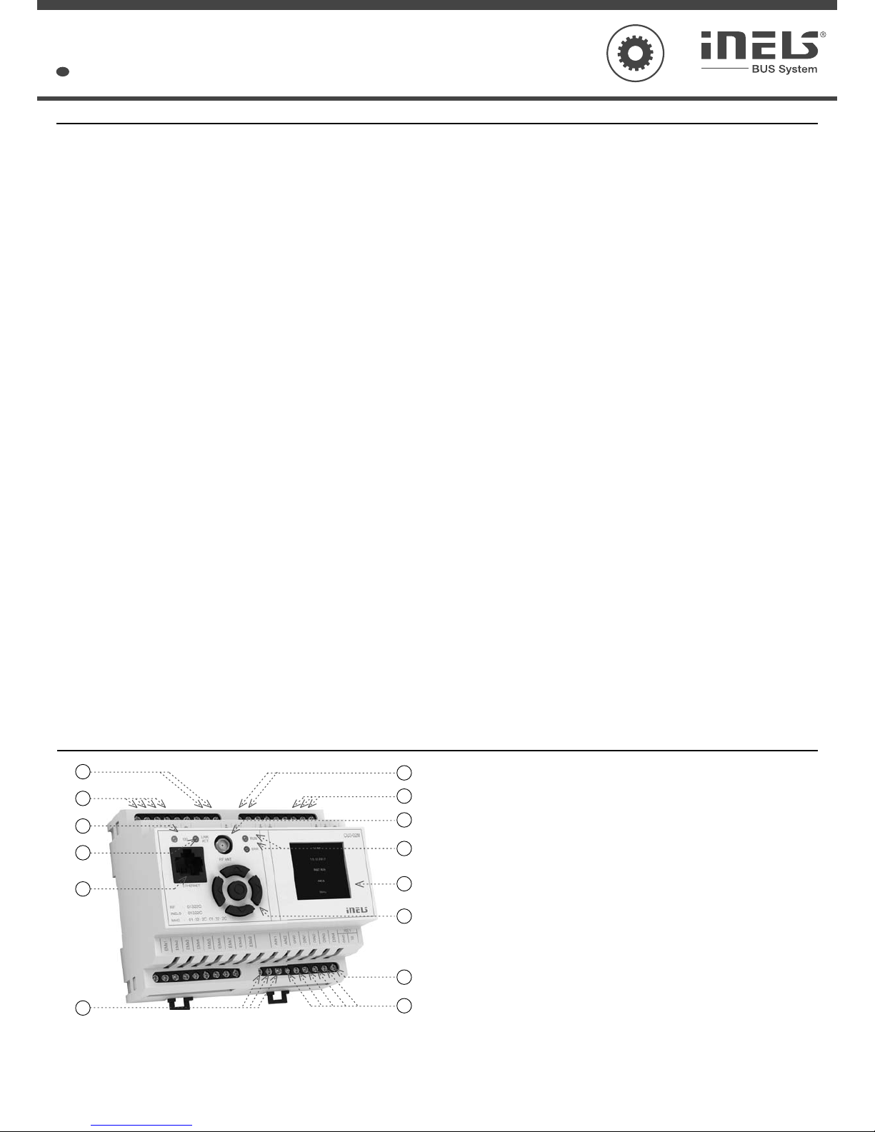
1. Data BUS1
2. Supply voltage terminals
3. LED indication Ethernet speed 100 Mbps
4. LED indication for Ethernet communication
5. Ethernet port 100 Mbps (RJ45)
6. Analog inputs 0-30 V DC
7. Data BUS2
8. System BUS EBM
9. SMA antenna connector (CU3-02M)
10. Operational state of unit LED indication
11. Information display
12. Routing buttons
13. Relay output NO/GND
14. Digital inputs
Page 2
CU3-01M, CU3-02M
CU3-02M
2/3
ashing - communication with BUS; ON - no communication
ashing - no proje ct, ON - unit STOP
displays the cu rrent status and settings
color OLED
128x128 / 1:1 aspect ratio
26 x 26 mm
using arrows
accuracy: 1s/day at 23 °C
4x NO or NC to GND (-) / 2 analogue input s 0 ÷ 30 V
relay output- NO/GND
max. 64 (2x32)
up to 576 units (CU3-01M (02M) and 8x MI3- 02M)
max. 32 units to one BUS line
max. 550 m (depen ds on power loss)
max. 500 m
up to 8 (regards to increasing the cycle turns)
RJ45 on the f ront panel
100 M bps
green - Ethernet communication / yellow - Ethernet speed 100 Mbps
192.168.1.1 (the IP address can be changed in the menu using the display and b uttons)
27 V DC, -20 / +10 %
110 mA (at 27V DC)
-20 to +55 °C
-25 to +70 °C
max. 80 %
IP 20 devices, IP 4 0 with cover in the switchboard
II.
2
any
to the switching board on th e EN60715 DIN rail
6-MODULE
max. 2. 5 mm
2
90 x 105 x 65 mm
250 g
RF Touch Compatibl e
868 MHz / 915 MHz / 916 MHz
bidirec tionally addressed m essage
SMA connector *
1 dB (part of package)
up to 100 m
Technical parameters
LED indication
Green LED RUN:
Red LED ERR:
OLED display
Typ e:
Resolution:
Visible are a:
Controlling:
The internal real-time clock:
Inputs
Inputs:
Outputs
Output:
Number of conn ected units (directly to the
CU3-01M (02M):
Expansion possibilities external BUS master:
Communication
BUS
Maximum number of unit s:
Maximum cable length:
System BUS EBM
Maximum cable length:
Number of conn ected ext.masters:
Ethernet
Connector :
Communicatio n speed:
Indicatio n of the Ethernet:
The default IP address:
Supply
Supply voltage / tolerance:
Rated current:
Operating conditions
Working temperature:
Storage tem perature:
Humidity:
Degree of protection:
Overvolt age category:
Degree of pollution:
Operatin g position:
Installation:
Design:
Terminal:
Dimensions:
Weight s:
iNELS RF Control interface
Communicati on protocol:
Transmitting frequency:
Signal transmission methods:
Output for RF antenna:
RF antenna:
Free space range:
* Max Tightening Torque for antenna connector is 0.56 Nm.
Page 3
02-72/2017
Rev.0
3/3
+
-
+
-
1+
1-
B
US
2
+
B
US
2
-
MAC: xx:xx:xx:xx:xx:xx
iNEL
S:
xxxxx
x
BUS
2 BUS1
BUS
2+ BUS2
-
BUS1+ BUS1
-
+
+
-
BUS1
BUS2
12V EZS
ELKO EP, s.r.o. | Palackého 493 | 769 01 Holešov, Všetuly | Czech republic | e-mail: [email protected]
TECHNICAL SUPPORT | E-mail: [email protected] | Mobil: +420 778 427 366 | Tel.: +420 573 514 276, +420 573 514 211 | Fax: +420 573 514 227 | www.inels.com
Warning
Before the dev ice is installed and oper ated, read this instructi on manual carefully and with f ull understanding an d Installation Guide System iNEL S3. The instructio n manual is designated for mounti ng the
device and for th e user of such device. It has to be att ached to electro-installation d ocumentation. The instruction manual can be also found on a web site w ww.inels.com. Attention, danger of injur y by
electrical current! Mounting and connec tion can be done only by a professional with an adequate electrical qualifi cation, and all has to be done while obser ving valid regulations. Do not touch parts of
the device that are energized. Dang er of life-threat! While mountin g, servicing, execut ing any changes, and repairing it is essential to obser ve safety regulations, norms, directi ves and special regulations
for working w ith electrical e quipment. Before you sta rt working with th e device, it is essential to have all wires , connected part s, and terminals de- energized. This instr uction manual contains o nly general
directions which need to b e applied in a particular installation. In the course of inspections and maintenance, always check (while de-energized) if terminals are tightened.
Connection
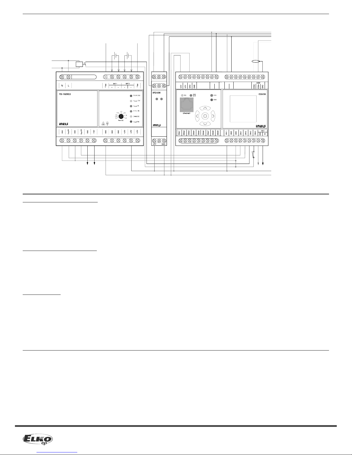
maximum of 32 units per line BUS; maximum 1A per line BUS
EBM to MI3-02M, MI3- 02M/iNELS2,
GSM3-01M or EMDC-64M
Auxiliary relay coil 230V AC/5 mA
switching contact e.g. VS116K
24 V battery
battery 1
12 V
battery 2
12 V
General instrucions
CONNECTION TO T HE SYSTEM, INSTALLATION BUS
iNELS3 peripheral unit s are connec ted to the system through the BUS installation. Installation BUS conduc tors are connected to the terminal unit s to BUS + and BUS-terminals, wires cannot be
interchanged. Fo r installation of BUS it is necess ary to use a cable with a t wisted pair of wires with a d iameter of at least 0.8 mm, the re commended cable is iNEL S BUS Cable, whose features bes t meet the
requirements of the BUS installation. Bearing in mind that in terms of all the properties iit is it is possib le in most cases also use the cable JYST Y 1x2 x0.8 or JYSTY 2x2x0.8, however it is not recommended
as the best option. In the case of a cable with two pairs of twisted wires it is not possible to use the second pair of the other for modulate d signal due to the speed of communications; it is not possible
within one ca ble to use one pair for one seg ment BUS and the second pair for t he second segment BUS. For ins tallation of BUS it is vi tal to e nsure th at it is ke pt at a di stance from th e power lines o f at leas t
30 c m an d mus t be ins tall ed i n acc ord ance wit h it s mec han ica l pro per ti es. To inc reas e me cha nica l re sist anc e of c abl es w e rec omm end installation into a con duit of suitable diame ter. Topo logy installatio n
of BUS is free except for a circle, each end of the BUS must terminate at terminals BUS+ and BUS-. While maintaining all the above requirements, the maximum length of one segment of the installation
BUS can reach up to 550 m. Due to the data communication and supply of units in one pair of wires, it is necessary to keep in mind the diameter of wires with regards to voltage loss on the lead and the
maximum current drawn. The maximum length of the BUS applies provided that they comply with the tolerance of the supply voltage.
CONNECTION TO THE SYSTEM, BUS SYSTEM EBM
System units MI3- 02M, MI3-02M/iNELS2, EMDC-64M and GSM3-01M connect to the system through the EBM BUS system. The BUS sys tem conductors are connected to the ter minals EBM+ and EBM-,
wires can not be interchanged. The BUS system EBM is essentially a symmetrical high-spee d RS485 inter face and, as such, subject to requirements of the appropriate conduit. When installing the EBM
BUS system it is ne cessary to obser ve all the requirements for the i nstallation of the RS4 85 interface. It is part icularly important to avo id overlapping with power line s (mai ntain a distance of at least 30 cm)
and pay attenti on to equipment generating e missions when these are loca ted in the vicinity of sy stem units or the EBM BUS manageme nt system. These emissions mus t be suppressed to a desired level .
For the EBM BUS system it is necessar y to use CAT5e UT P cable or higher, or an FTP CAT5e and higher STP CAT5e or higher. For the EBM BUS management system it is not possible to use JYST Y cable or
iNELS BUS Cable, which are used to guide the installation of BUS. EBM s ystem BUS topology is strictly linear and there are no b ranches on the BUS. Both ends of the EMB BUS system require to terminate
by using a resistor with a nominal value of 120Ω resistance. Units CU3-01M, CU3-02M, MI3-02M, MI3-02M/iNELS2 and GSM3-01M this resistor is inser ted between the terminals and EBM+ EBM-. The unit
EMDC-64M resistor is included with the unit and closing is done by shorting adjacent terminals TERM and EBM+.
SUPPLYING THE SYST EM
For supplyin g power to system units , it is possible to use the po wer sources of ELKO EP titled PS3-100/iNELS. We recommend backing up t he system with ba ckup batteries conn ected to the source o f PS3-100/ iNELS
(see sample diagram of connectin g the control system).
Installatio n Manual CU3-0xM central uni t, installation manual iNEL S and confi guration sof tware iDM3 are available for d ownload on the website ww w.inels.cz sec tion for system part ners.
To obtain credentials, p lease contact us at the email ad dress [email protected] .
 Loading...