

Inel ST-01R, ST-01RZ, ST-01RS Instructions For Installation And Use Manual
ST-01R roller blind control unit
Instructions for installation and use
Safety guidelines
Basic guidelines
The ST-01R controller can be safely installed and used provided all of the following instructions of installation and use as well as obligatory health
and safety regulations are adhered to.
The installation and repairing of electrical equipment should be carried out only by persons with appropriate legal qualifications.
Reconstructing or making changes to the ST-01R controller is forbidden. During the guarantee period repairs only the manufacturer may carry out
repairs. Even after the guarantee period has expired only original parts and accessories may be used.
The guarantee is only valid when the ST-01R controller has been used in accordance with the manufacturer’s instructions. The boundary values
given in the technical specifications must NOT be exceeded under any circumstances.
Supplementary safety regulations
When installing, using or carrying out maintenance work all binding health and safety regulations should be followed. Particular attention should be
paid to the following:
1. European Standards
2. Fire regulations
3. Accident avoidance regulations
.
Danger – this signal indicates danger to the user’s life and health if appropriate safety measures are not taken.
used again after recycling.
The following comments serve as general guidelines to the application of INEL drivers with other devices. These guidelines must
always be adhered to when installing and operating these devices
Warning – this signal warns of possible damage to the control system or other equipment if appropriate safety measures are not taken.
Before installing the control system and setting the end switches check all bolt connections are properly fastened.
Follow all health and safety regulations relevant to the equipment (e.g. gates, roller blinds) used.
When changing fuses the equipment must be first disconnected from the mains, the fuses changed and only then may the equipment be
reconnected to the mains.
The ST-01R controller should be installed in accordance with appropriate safety regulations and with appropriate safety devices.
INEL equipment connected to the mains beyond a building’s safety fuse system needs to be installed with its own safe disconnecting
devices (e.g. safety fuses and safety switches) in such a way so as to ensure that all the units may be easily and safely cut off from the
mains.
Electric wiring and cables should be regularly checked to ensure the insulation is intact and there are no breaks in the wire.
If any damage to the wiring is found, the unit should be immediately disconnected from the mains and the damaged wiring replaced.
Before connecting any equipment, one should first make sure that it is adapted to be used with the local voltage in the mains.
Do not allow children to play with any of the control devices.
Keep all remote control devices out of the reach of children.
Observe the opening or shutting of the blinds, shutters, awnings or gates and ensure all persons stand clear until the operation is
completed.
Control system operators need to undergo preliminary instruction and training and also be made aware of all the potential dangers that
can be encountered. A person should only be authorised to use the control system only once the employer, administrator or owner is
satisfied that that person has been properly instructed.
It is not permitted to dispose of waste equipment together with other waste. Dispose only in specially designated areas. The household
plays a key role in the recycling of waste equipment. By correct sorting of waste, including waste equipment and batteries, household
members ensure that the equipment is not disposed together with household waste, but in specially designated areas, and thus may be
GENERAL COMMENTS REGARDING HAZARDS AND SAFETY PRECAUTIONS
PERSONAL SAFETY WARNING
1
CONTROLLER DESCRIPTION
ST-01R
The ST-01R controller is a device used to control locally or remotely the operation of roller blinds and shutters. The device is intended for
flush mounting in a double depth wall box.
Local control is achieved with a manual button connected to the manual input. The controller has a deadman function - a short press of the
manual on/off button starts a full cycle of opening or closing the roller blind (the time of applying voltage to the motor is factory set at 100
seconds).
Remote control is possible with the use of the following remote controllers: PIL-02/04XB, PIL-01PT, PIL-01/04NS, PIL-01/05/09/19DL,
PIL-19/99DLT, PIL-01/05/09/19PM, PIL-19/99PMT.
ST-01RZ (shutter controller)
The controller allows for precise setting (changing angle) of shutter slats
locally with a manual button and remotely with remote controllers: PIL-01/04NS, PIL-05/09/19DL, PIL-19/99DLT,
PIL-05/09/19PM, PIL-19/99PMT.
The manual button has a dual function, depending on press duration:
- below 1 second - start with deadman function (100 seconds),
- longer than 1 second - short activation of the motor - setting slat angle.
When controlled remotely, the device receives commands from remote controllers operating in normal or shutter mode. Commands send in
normal mode start the full opening or closing cycle. In shutter mode, every command starts a motor for a short time - setting slat angle.
ST-01RS (light controller)
This controller allows for switching 230 V AC electrical receivers on and off without time limits.
It can be controlled locally with a manual button and remotely with remote controllers: PIL-02/04XB, PIL-01PT, PIL-01/04NS,
PIL-01/05/09/19DL, PIL-19/99DLT, PIL-01/05/09/19PM, PIL-19/99PMT.
The manual button operates in a loop - “on - off -on”.
When controlled remotely, the device receives commands from remote controllers operating in normal mode. Remotes from the XB series
operate in the “on - off - on” loop. Remotes from the PT, NS, PM and DL series work as follows:
- “up” – on,
- “stop” – off,
- “down” – off.
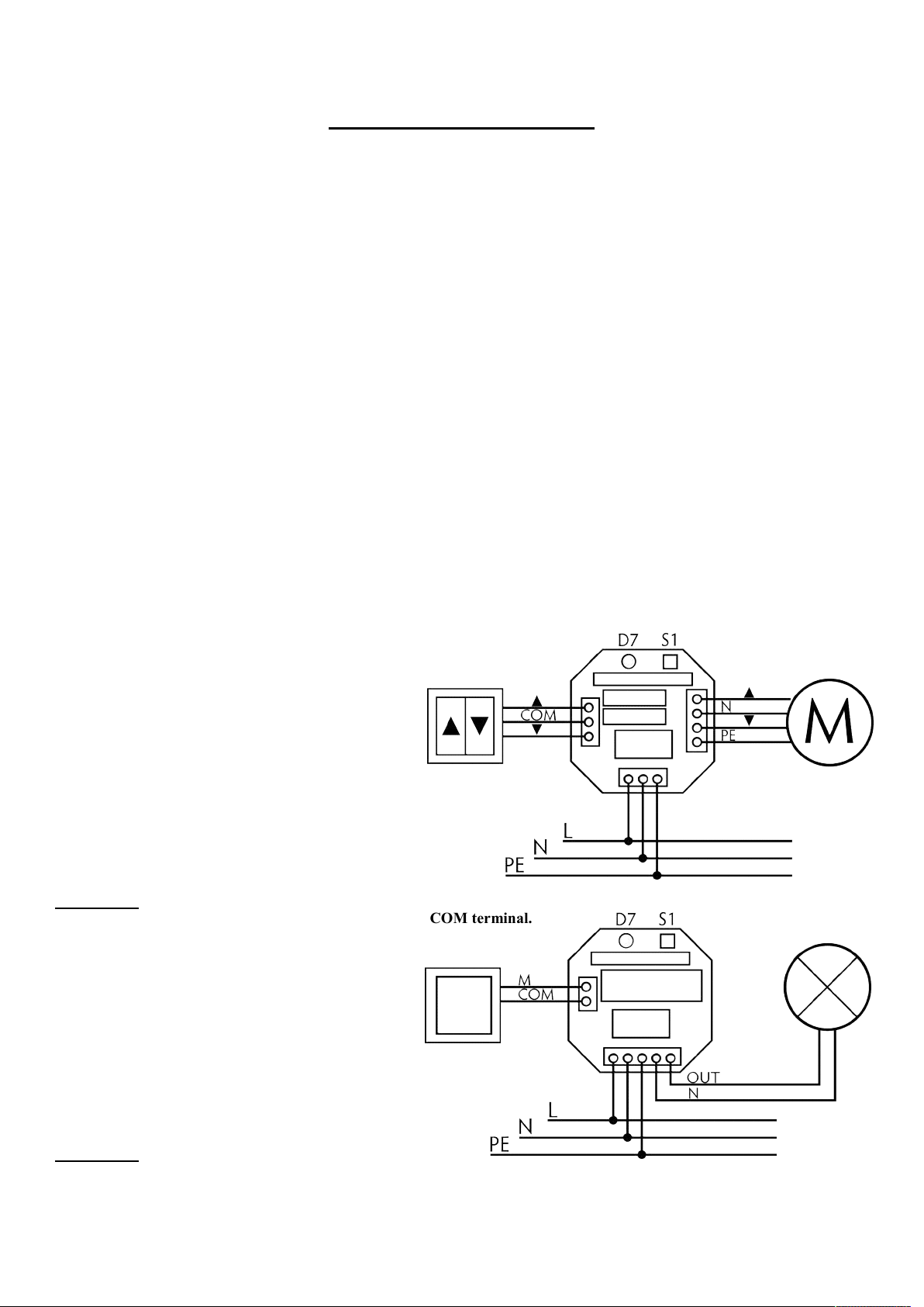
Connecting ST-01R and ST-01RZ controllers
L installation L1 wire brown
N installation N wire blue
PE installation PE wire yellow-green
MOTOR motor connection
PE motor protective wire yellow-green
▲ motor up wire brown
N motor neutral wire blue.
▼ motor down wire black
MANUAL manual button connection
▲ to up button
COM to common terminal
▼ to down button
WARNING:
The shutter switch works by connecting terminals to the COM terminal.
DO NOT CONNECT TO MAINS.
Connecting ST-01RS controllers
L installation L1 wire
N installation N wire
PE protective wire
OUT receiver L wire
N receiver N wire
MANUAL manual button connection
M to Up button
COM to common terminal
WARNING:
The shutter switch works by connecting terminals to the COM terminal.
DO NOT CONNECT TO MAINS.
2
 Loading...