

Inel CRS-435XG Operation And Installation Manual, Safety Notes

CRS-435XG
CONTROL UNIT WITH ROLLING CODES
designed for controlling drives of window shutters, gates and roller door.
Operation and installation manual
Safety notes
Basic notes
The CRS-435XG control unit is supplied in a condition allowing for safe operation and use, provided that all the guidelines contained in this
operation manual and applicable to the given use (e.g. gate or shutter), as well as current safety and accident prevention regulations are observed.
The electrical components of the product may only be installed and repaired by qualified and licensed technicians.
Any modifications or changes to the product are not allowed. Warranty repairs may only be carried out by the manufacturer. Only genuine spare
parts and accessories may be used for post-warranty repairs.
The operating safety of CRS-435XG unit is guaranteed provided it is used according to the manufacturer's specification. The limit values specified
in the technical specification must be strictly observed.
Additional safety regulations
All important safety regulations and rules for preventing accidents applicable to the given application (e.g. gate or shutter) must be adhered to
when installing, starting up and maintaining the control unit. The following regulations are to be taken into account in particular:
1. Fire safety regulations.
2. Accident prevention regulations.
GENERAL HAZARD AND SAFETY NOTES
The notes provided herein are general guidelines for using INEL control units in conjunction with other equipment. These guidelines are to be
strictly observed when installing and operating the equipment.
Warning - a warning note on potential damage to the control unit or other assets
in case of failure to adopt proper means of safety.
Danger - indicates an existing danger to life and health of the user in case of failure to apply appropriate means of safety.
• Check that all screw connections are tight prior to installing the unit and setting the limit switches.
• Observe safety and accident prevention regulations applicable to the given use (e.g. shutter, gate).
• Before replacing fuses, unplug all power supply cables, then replace the fuse and reconnect the power cables.
• The CRS-435XG unit must be installed with adequate protections and protective devices required by applicable regulations. The
control units featuring crushing protection with a sensor installed on the gate, which the protection acts upon contact of foreign body
with the gate, must not cause any injuries caused from the movement of the gate.
• For INEL equipment with constant mains input to the unit, a switch ensuring safe voltage interruption (e.g. fuse-switch), must be used
apart from the safety fuse, installed in such way that all the connections can be easily disconnected.
• Regularly inspect all cords and cables for damage to insulation and local breaks.
• In case of identifying cord damage, immediately disconnect the damaged cables from the mains and replace the damaged cords.
• Before connecting the product to the mains it must be confirmed that its rated voltage conforms to the local mains voltage.
CAUTION - IMPORTANT TO HUMAN SAFETY:
• do not allow children to play with the control unit;
• keep remote control devices out of children's reach;
• observe the moving system (e.g. gate, awning) and keep any bystanders away until full shutting or opening;
• all users of the gate must be trained or instructed on the principles of its operation and the related operating hazards. Persons may be
deemed as duly trained if the employer, administrator or owner has permitted them to open the gate, and instructed them on how to use
it.
It is not permitted to dispose of waste equipment together with other waste. Dispose only in specially designated areas. The household
plays a key role in the recycling of waste equipment. By correct sorting of waste, including waste equipment and batteries, household
members ensure that the equipment is not disposed together with household waste, but in specially designated areas, and thus may be
used again after recycling.
General description
The control unit is used to control drives powered by 230 VAC voltage. The unit may be controlled locally (with a button) or
wirelessly with a remote control. It is fitted with a photocell input. In order for the unit to accept commands from a remote control, the
remote's code must be registered in the unit. The unit can register up to 15 different codes. Commands sent from the remote control or
local button work in the following sequence: opening motion, stop, closing motion, stop. A signal received from the photocell in the
closing phase will stop the drive and prevent it from starting closing motion again until the photocell signal stops. Opening motion will be
allowed regardless of photocell signal. Operating time in any given direction is limited. The limit can be adjusted with a knob between 10
and 120 s.
TECHNICAL SPECIFICATIONS
Housing
Material GW plastic
Colour Grey
Dimensions 150 x 110 x 70 mm
Supply voltage
Rated 230 VAC
Frequency 50 Hz
Operating frequency
433.92 MHz
Temperature range
Operating -5°C ... +45°C
Storage -25°C ... +70°C
Humidity
up to 93% without condensation
Output relays
10A / 250 VAC
Output fuses
250VAC/ 3.15 A
Output current
Rated 3 A
Terminals
Screw
Mass
560 g
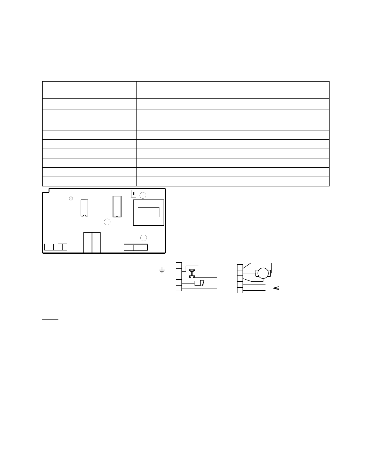
KEY COMPONENT LAYOUT
SW2 - teaching button (see programming)
R25- setting opening/closing time
PR4,PR3 - relays
L5 - signal diode
1..5, 9..11 – connection of motors, photocells, limit switches, edges and bars
BZ2 - drive fuse (3.15 A)
BZ3 - power supply fuse (315 mA)
TR- power transformer
L1 - 230V AC supply – L1 wire (phase)
N - 230V AC supply – N wire (neutral)
CONNECTION
1,2 Photocell power
3,5 Manual operation button [M] (NO)
4,5 Photocell [F] (NC-normally closed)
9 Drive cable [S] (closing)
10 Drive cable [S] (opening)
11 Drive cable [S] (common)
L1,N Power supply ~230V/50Hz
Connecting the control unit
Connect AC power (230 V) to the N and L1 terminals (it is crucial that the connection is made through an earth leakage circuit
breaker). Connect drive motor to terminals 9, 10 and 11, with 11 being common for both drive directions; the wires connected to
terminals 9 and 10 should be connected in such a way that the photocell blocks closing motion.
Terminals 1 and 2 are used to supply +12V DC voltage for the photocell. Terminals 1 and 5 are connected to ground. Terminals 3 and
5 are used for local control input, and terminals 4 and 5 - for photocell signal input. The local control circuit is fitted with a monostable
normally open switch, which shorts the input to ground when activated. As for the photocell, it should normally short the unit's input to
ground, and open it when activated.
Programming the control unit
The control unit is able to 'learn' and memorise max. 15 (fifteen) different codes. If you press the SW2 switch, the control unit will
switch into 'learning' mode. This will be indicated by the L5 indicator diode (red) lighting up for ca. 1 second, after which it will give a
series of 0.5 sec. flashes in the amount equal to the number of currently memorised codes. If the control unit has no codes i n its memory,
the L5 indicator diode will light up for ca. 1 second, but there will be no flashes. Now press (and hold for a while) a button on the remote,
for which the code is to be memorised. When the control unit accepts the remote code, the L5 indicator diode will light up again for ca. 1
sec. and emit a series of flashes. If the number of flashes increased, this means the control unit has 'learned' another code. If the number of
flashes did not increase, then either the received code was already known to the control unit, or the control unit has alread y memorised
15 codes and its memory is full. The unit will return to normal operation after receiving a signal from the remote control or after 10
seconds. The 'learned' codes are stored even if power is switched off and on again.
Deleting memorised codes
If you need to delete all memorised codes, press and hold the SW2 button for 10 seconds. The deletion of all codes from the
control unit's memory will be indicated by the L5 indicator diode lighting up. After deleting the codes you can return to normal operation
mode by releasing the SW2 button. (If you now want to memorise new codes, you must enter the 'learning' mode again).
If the control unit does not know any codes (its memory is empty), you cannot control it with a remote control, but you can use the
local button (manual control).
SW2
R25
L5
R
A
D
I
O
PR4 PR3
BZ2
BZ3
L1 N 9
11
10
TR
4
5
1 3 2
connect via 6A earth
leakage circuit breaker
with the sensitivity of
50mA
230V~ 50Hz
S
9 L111
10
N
F
M
+12V FOT
1 4 3 2 5
 Loading...