

Indy R4600PC, R4400SC Installation Manual

Indy™ R4600PC™ 133 MHz and
R4400SC
™
175 MHz
CPU Upgrade Installation Guide
Document Number 007-9219-003

CONTRIBUTORS
Written by Judy Muchowski
Illustrated by Dany Galgani, Maria Mortati
Production by Chris Everett
Cover design and illustration by Rob Aguilar, Rikk Carey, Dean Hodgkinson,
Erik Lindholm, and Kay Maitz
©Copyright 1995, Silicon Graphics, Inc.— All Rights Reserved
This document contains proprietary and confidential information of Silicon
Graphics, Inc. The contents of this document may not be disclosed to third parties,
copied, or duplicated in any form, in whole or in part, without the prior written
permission of Silicon Graphics, Inc.
RESTRICTED RIGHTS LEGEND
Use, duplication, or disclosure of the technical data contained in this document by
the Government is subject to restrictions as set forth in subdivision (c) (1) (ii) of the
Rights in Technical Data and Computer Software clause at DFARS 52.227-7013 and/
or in similar or successor clauses in the FAR, or in the DOD or NASA FAR
Supplement. Unpublished rights reserved under the Copyright Laws of the United
States. Contractor/manufacturer is Silicon Graphics, Inc., 2011 N. Shoreline Blvd.,
Mountain View, CA 94039-7311.
Silicon Graphics is a registered trademark and Indy and Indy Cam are trademarks of
Silicon Graphics, Inc.
Indy™ R4600PC™ 133 MHz and R4400SC™ 175 MHz
CPU Upgrade Installation Guide
Document Number 007-9219-003

Contents
The Upgrade Package 2
Installing the Software 2
Turning Off Your Indy Workstation 3
Removing the Top Cover 4
Attaching the Wrist Strap 5
Checking Your System’s PROM Version: R4600PC 133 MHz Upgrade 6
Replacing the PROM Chip 8
Removing the GIO Option Board 8
Removing the Graphics Board 10
Replacing the PROM Chip 14
Replacing the Graphics Board 18
Replacing the GIO Option Board 20
Replacing the CPU Module 23
Replacing the Cover 26
Turning on the Workstation 27
Product Support 28
iii


List of Figures
Figure 1 Turning off the Indy workstation 3
Figure 2 System power off notifier 3
Figure 3 Removing the top cover from the Indy workstation 5
Figure 4 Okay to Power Off Notifier 6
Figure 5 Starting Up the System Notifier 7
Figure 6 Locating the GIO option board 9
Figure 7 Removing the screws from the rear of the workstation 9
Figure 8 Removing the screws from the GIO option board 10
Figure 9 Removing the screws from the graphics board’s
I/O connector 11
Figure 10 Removing the screws from the graphics board 12
Figure 11 Disconnecting the graphics board from the
system board 13
Figure 12 Locating the PROM chip on the system board 14
Figure 13 Removing the PROM chip 15
Figure 14 Lining up the PROM chip 16
Figure 15 Pressing the PROM chip into the socket 17
Figure 16 Connecting the graphics board to the system board 18
Figure 17 Replacing the screws on the graphics board’s
I/O connector 19
Figure 18 Inserting the screws on the graphics board 19
Figure 19 Inserting the GIO board’s I/O connector through
the backplane 20
Figure 20 Inserting the screws from the rear of the workstation 21
Figure 21 Installing a single-width GIO option board 22
Figure 22 Locating the CPU module 23
Figure 23 Removing the two screws from the CPU module 24
Figure 24 Disconnecting the CPU module 24
v

Figure 25 Installing the CPU module 25
Figure 26 Replacing the top cover on the Indy workstation 26
Figure 27 Turning on the Indy workstation 27
vi

Upgrading the Indy Workstation CPU
This manual explains how to install the CPU upgrade on an Indy
workstation.
Note: If you received a CD with the upgrade, you must install the software
first. Read the software release notes on the CD for software installation
instructions before installing the hardware.
To install the hardware, you will complete these steps:
• Shut down the system.
• Remove the cover.
• Remove and replace the PROM chip on the system board. (If you are
upgrading to an R4600PC 133 MHz CPU, you may not have to replace
the PROM. See the section “Checking Your System’s PROM Version:
R4600PC 133 MHz Upgrade” on page 6.)
• Remove and replace the CPU module.
• Replace the cover and restart your system.
Read through this guide first before starting the upgrade. If you find a term
you haven’t seen before, see your workstation’s Owner’s Guide. The glossary
contains definitions of many of the terms used in this guide.
Caution: Make sure you have a full backup of your system before powering
down and installing the upgrade. For instructions on backing up your
system, choose “Online Books” from the Help toolchest. Then select the
Personal System Administration Guide and search for “Backing Up and
Restoring Files.”
1

Upgrading the Indy Workstation CPU
The Upgrade Package
Your upgrade package includes all of the following items. If anything is
missing, contact your sales representative.
• PROM chip in an antistatic bag
• CPU module in an antistatic bag
• open-ended wrench to remove standoffs and hexnuts
• Phillips screwdriver
• chip removal tool to remove the PROM chip
• anti-static wrist strap
• Indy R4600PC 133 MHz and R4400SC 150 MHz CPU Upgrade Installation
Guide (this manual)
• CD (not in all upgrades)
In addition, some upgrade packages include a system label to attach to the
underside of the Indy workstation.
Installing the Software
2
If you received a CD with the upgrade, read the release notes on the CD for
instructions on installing the software. Install the software before installing
the hardware.

Turning Off Your Indy Workstation
Press and release the power button on the front of the workstation, as shown
in Figure 1, to power off the system.
Note that it’s not necessary to shut down the system software before
pressing the power button.
Turning Off Your Indy Workstation
Power button
Figure 1 Turning off the Indy workstation
The notifier shown in Figure 2 appears on your screen within a few seconds
and the LED blinks green and amber. Then the system powers off
automatically within the next minute.
Figure 2 System power off notifier
3

Upgrading the Indy Workstation CPU
Removing the Top Cover
Follow these steps to remove the top cover of your Indy workstation:
1. If the monitor is on top of the workstation, move it to one side.
Caution: Monitors are very heavy. Have someone help you move it.
2. Disconnect the following cables from the back of the Indy workstation:
• power cable
• monitor cable
• IndyCam™ cable (if connected)
• EtherNet AUI cable (if connected)
Disconnecting the IndyCam and EtherNet AUI cables is optional.
Removing them gives you more room when removing the screws on
either side of the graphics board connector.
4
Removing the Top Cover
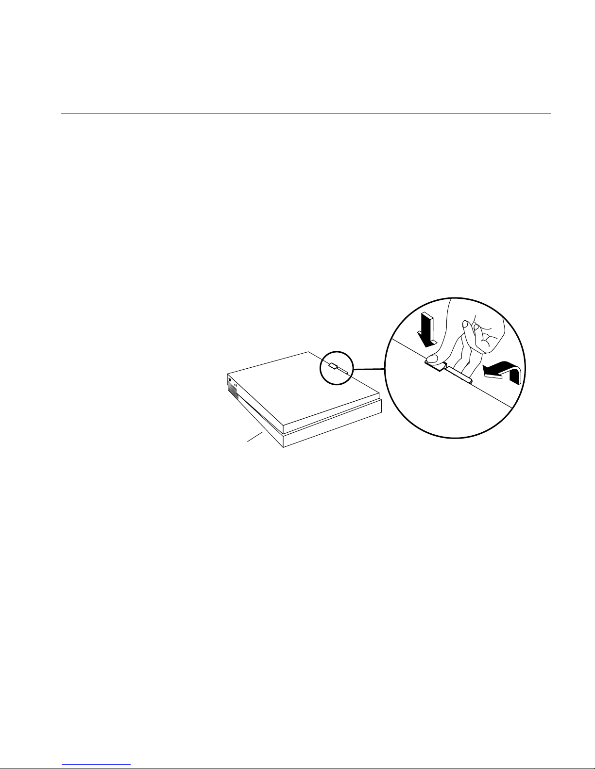
3. Facing the front of the Indy workstation, place your right thumb on the
small channel at the back of the cover, and your second and third
fingers under the finger ledge, as shown in Figure 3.
4. Snap the cover loose by bracing your thumb against the lip and
pushing up the finger ledge with the second and third fingers, followed
by a small push toward the front.
5. Slide the cover forward about one inch and tilt it up to remove it.
Tip: It may be difficult to release the cover the first time, and you may have
to use some force.
Front
Figure 3 Removing the top cover from the Indy workstation
Attaching the Wrist Strap
Wear the wrist strap to prevent the flow of static electricity, which can
damage the components in the Indy workstation.
Caution: The components inside the Indy are extremely sensitive to static
electricity. Handle all chips and modules carefully, and wear the wrist strap
shipped with the upgrade package while replacing parts inside the system.
To attach the wrist strap, follow these steps:
5
 Loading...