

Indy Presenter Owner's Manual

Indy Presenter™ Owner’s Guide
Document Number 007-9224-001

CONTRIBUTORS
Written by Judy Muchowski
Illustrated by Dany Galgani, Kay Maitz, Derrald Vogt
Engineering contributions by Dan Evanicky, Bert Keely, Alice Meng, Steve Siefert
Production by Chris Glazek
© Copyright 1994, Silicon Graphics, Inc.— All Rights Reserved
This document contains proprietary and confidential information of Silicon
Graphics, Inc. The contents of this document may not be disclosed to third parties,
copied, or duplicated in any form, in whole or in part, without the prior written
permission of Silicon Graphics, Inc.
RESTRICTED RIGHTS LEGEND
Use, duplication, or disclosure of the technical data contained in this document by
the Government is subject to restrictions as set forth in subdivision (c) (1) (ii) of the
Rights in Technical Data and Computer Software clause at DFARS 52.227-7013 and/
or in similar or successor clauses in the FAR, or in the DOD or NASA FAR
Supplement. Unpublished rights reserved under the Copyright Laws of the United
States. Contractor/manufacturer is Silicon Graphics, Inc., 2011 N. Shoreline Blvd.,
Mountain View, CA 94043-1389.
Dukane is a registered trademark of Dukane Corporation. Silicon Graphics is a
registered trademark and Indy, Indy Presenter, and Indybag are trademarks of
Silicon Graphics, Inc.
Indy PresenterTM Owner’s Guide
Document Number 007-9224-001

Contents
Introduction ix
1. Installing the Indy Presenter Hardware
and Software 1
The Indy Presenter Package 1
Identifying Your Indy’s Graphics Board 2
Checking the PROM Chip Version 3
Removing the Top Cover 6
Attaching the Wrist Strap 7
Removing the GIO Option Board 8
Replacing the PROM in an Indy Workstation 12
Removing the Indy Graphics Board 12
Replacing the PROM Chip 15
Replacing the Graphics Board 19
Installing the Indy Presenter Adapter Board 23
Installing the Indy Presenter XZ Adapter Board 30
Turning Off Your Indy Workstation 31
Removing the Top Cover 32
Attaching the Wrist Strap 33
Installing the Board 33
Replacing the Top Cover and Connecting the Cables 41
Installing the Software 42
iii

Contents
2. Setting Up and Using the Indy Presenter 43
Setting Up the Indy Presenter 43
Connecting the Cables 44
Using the Indy Presenter 48
Turning On the Indy Presenter 48
Turning Off the Indy Presenter 49
Setting Up on the Dukane Customized Projector 49
Using the Indy Presenter Software 54
Using the Monitor Control Panel 54
Turning on the Indy Presenter 54
Restarting the Indy Presenter 55
Adjusting the Brightness 55
Switching to 15-Bit Mode 56
Using the Audio Control Panel 56
Adjusting the Volume and Tone of the Speakers 57
Using Headphones 58
Transporting the Indy Presenter 58
Transporting the Dukane Overhead Projector 59
Cleaning and General Care of the Indy Presenter 60
Using a Screen Saver 61
3. Troubleshooting 63
Common Problems 63
No Image on the Indy Presenter 63
Image Is Too Light or Too Dark 64
Faint Vertical Streaks Above or Below Edges of Windows 64
No Image on the Overhead Projector or Image Is Reversed 65
No Sound From the Stereo Speakers 65
Diagnostics Tests For the Indy Presenter 66
Removing the Indy Presenter Adapter Board 67
Removing the Indy Presenter XZ Adapter Board 69
Returning the Presenter to Silicon Graphics 71
Product Support 71
iv

4. Technical Specifications and Regulatory Information 73
Technical Specifications 73
Manufacturer’s Regulatory Declarations 76
Electromagnetic Emissions 76
Electrostatic Discharge 77
Shielded Cables 77
Product Safety 77
A. About Liquid Crystal Display (LCD) Technology 79
Display 79
Differences Between LCD and CRT Technology 80
Quality 81
Backlight Brightness 81
Index 83
v

Contents
vi

Figures
Figure 1-1 System Shutdown Notifier 3
Figure 1-2 Okay to Power Off Notifier 4
Figure 1-3 Starting Up the System Notifier 4
Figure 1-4 Turning Off the Indy Workstation 5
Figure 1-5 Removing the Top Cover From the Indy Workstation 6
Figure 1-6 Indy Workstation With Single-Width GIO Option
Board 8
Figure 1-7 Removing the Screws From the GIO Board Connector 9
Figure 1-8 Removing the Screws From the GIO option Board 10
Figure 1-9 Disconnecting the GIO Option Board 10
Figure 1-10 Removing the Hexnut Screws From the Rear Panel 12
Figure 1-11 Removing the Screws From the Graphics Board 13
Figure 1-12 Disconnecting the Graphics Board From the System
Board 14
Figure 1-13 Locating the PROM Chip on the System Board 15
Figure 1-14 Removing the PROM Chip 16
Figure 1-15 Lining Up the PROM Chip 17
Figure 1-16 Pressing the PROM Chip Into the Socket 18
Figure 1-17 Positioning the Graphics Board Over the System
Board 19
Figure 1-18 Seating the Graphics Board’s Connectors 20
Figure 1-19 Standoff Screw 21
Figure 1-20 Inserting the Screws on the Graphics Board 21
Figure 1-21 Replacing the Screws on the Backplane 22
Figure 1-22 Removing the Faceplate From the GIO Option Port 23
Figure 1-23 The Indy Presenter Adapter Board 24
Figure 1-24 Positioning the Adapter Board Over the Graphics
Board 25
vii

Figures
Figure 1-25 Seating the Adapter Board’s Connectors 26
Figure 1-26 Inserting the Screws on the Rear Panel 27
Figure 1-27 Securing the Adapter Board 28
Figure 1-28 Connecting the Audio Cable 29
Figure 1-29 Turning Off the Indy Workstation 31
Figure 1-30 Removing the Top Cover 32
Figure 1-31 The Indy Presenter XZ Adapter Board 33
Figure 1-32 Removing the Faceplate From the GIO Option Port 34
Figure 1-33 Installing the Metal Bracket 35
Figure 1-34 Inserting the Screws on the Exterior of the Bracket 36
Figure 1-35 Positioning the Indy Presenter XZ Adapter Board 37
Figure 1-36 Inserting the Screws on the XZ Adapter Board 39
Figure 1-37 Attaching the External Screws 40
Figure 1-38 Replacing the Top Cover on the Indy Workstation 41
Figure 2-1 Placing the Indy Presenter on Top of the Indy
Workstation 44
Figure 2-2 Interface Cable Connector 45
Figure 2-3 Connecting the Interface Cable to the Indy Presenter 45
Figure 2-4 Connecting the Interface Cable: Indy Presenter
Adapter 46
Figure 2-5 Connecting the Interface Cable: Indy Presenter XZ
Adapter 46
Figure 2-6 Connecting the Power Cable 47
Figure 2-7 Turning On the Indy Workstation and the Indy
Presenter 48
Figure 2-8 Removing the Backlight Panel 51
Figure 2-9 Placing the Presenter on the Overhead Projector 52
Figure 2-10 Replacing the Backlight Panel 53
Figure 2-11 Rotating the Base for Packing the Indy Presenter 59
viii

Figure 3-1 Removing the Audio Cable 67
Figure 3-2 Removing the External Screws 67
Figure 3-3 Removing the Screws from the Adapter Board 68
Figure 3-4 Removing the Audio Cable and the External Screws 69
Figure 3-5 Removing the Screw from the XZ Adapter Board 70
Figure 4-1 Japanese VCCI Class 1 Statement 76
ix

Figures
x

Introduction
Congratulations on purchasing the Indy PresenterTM, the world’s first
1024 x 768 full-color, flat-panel monitor with stereo speakers and overhead
projection capability.
This guide explains how to install the necessary hardware for the Indy
Presenter in the IndyTM workstation, how to set up the Indy Presenter as a
monitor for your workstation, and how to use the Indy Presenter on the
Silicon Graphics® customized Dukane® overhead projector.
You will also learn how to use the Indy Presenter software, how to transport
the Indy Presenter, how to take care of it, and how to troubleshoot if you
have problems.
Read this guide once all the way through before you start to work. Then
you’ll be familiar with the Indy system and the parts you’ll be working with.
If you find a term you haven’t seen before, refer to your system owner’s
guide. The glossary in the owner’s guide contains definitions of many of the
terms used in this manual.
xi

Introduction
xii

Chapter 1
1. Installing the Indy Presenter Hardware
and Software
Before using the Indy Presenter, you need to prepare your Indy workstation
by installing some hardware and software.
To install the hardware, you will complete these steps:
• Identify which graphics board is installed in your Indy workstation.
• Shut down the system and check the version of your PROM chip from
the Command Monitor. (If your Indy has XZ graphics, you do not have
to do this step.)
• Remove the cover.
The Indy Presenter Package
• Remove and replace the PROM chip on the system board (if necessary).
• Install either the Indy Presenter adapter or the Indy Presenter XZ
adapter, depending on your system’s graphics configuration.
• Replace the cover.
• Connect the cables and restart your system.
Your Indy Presenter package includes all of the following items. If anything
is missing, contact your sales representative.
• Indy Presenter flat-panel monitor
• Power cable and interface cable
• Indy Presenter adapter board or the Indy Presenter XZ adapter board in
an antistatic bag
• Bag of hardware for installing the adapter board
1

Chapter 1: Installing the Indy Presenter Hardware and Software
• PROM chip in an antistatic bag
• Chip removal tool to remove the PROM chip
• Open-ended wrench to remove standoffs and hexnuts
• Phillips screwdriver
• Antistatic wrist strap
• Cleaning kit
• Indy Presenter Owner’s Guide (this manual)
• Compact disc (CD-ROM)
Identifying Your Indy’s Graphics Board
Before starting the installation process, you need to know whether your Indy
has the Indy graphics board or the Indy XZ graphics boardset. Follow these
steps:
1. From the Desktop toolchest, select “Unix Shell.”
2. At the shell prompt, type:
hinv
• If you see “Graphics board: GR3-XZ,” your system has the Indy XZ
graphics. Type exit to exit the shell, and go to “Installing the Indy
Presenter XZ Adapter Board” on page 30.
• If you see either “Graphics board: Indy 24-bit” or “Graphics board:
Indy 8-bit,” check the version of your graphics board by typing:
/usr/gfx/gfxinfo
If you see “NG1 revision 3” or greater, your system has the Indy
graphics. Type exit to exit the shell, and go to “Checking the
PROM Chip Version” on page 3.
If you see either “NG1 revision 1” or “NG1 revision 2,” you were
one of the first purchasers of an Indy system. You need to upgrade
your graphics board, free of charge. Contact your local Silicon
Graphics support office for a free graphics board upgrade. When
2
Checking the PROM Chip Version
You may or may not need to replace your system’s PROM chip, depending
what PROM version you have. You check the version of the PROM chip from
the Command Monitor while shutting down your system.
Follow these steps to check your system’s PROM version:
1. Shut down the system.
Checking the PROM Chip Version
you have the new graphics board, start with “Checking the PROM
Chip Version” on page 3. When you reach the section “Replacing
the Graphics Board” on page 19, install the new graphics board.
■ Place the cursor over the word “System” in the Toolchest in the
upper left corner of your screen.
■ Press and release the left or right mouse button so that you see the
menu.
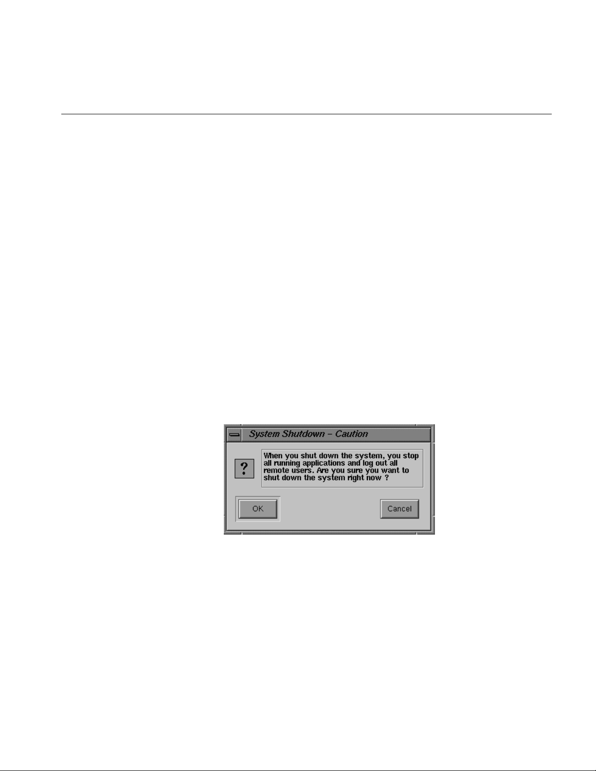
■ Click on “System Shutdown.”
After a few seconds you see the notifier shown in Figure 1-1.
Figure 1-1 System Shutdown Notifier
■ Click OK to shut down without powering off the system.
3
Chapter 1: Installing the Indy Presenter Hardware and Software
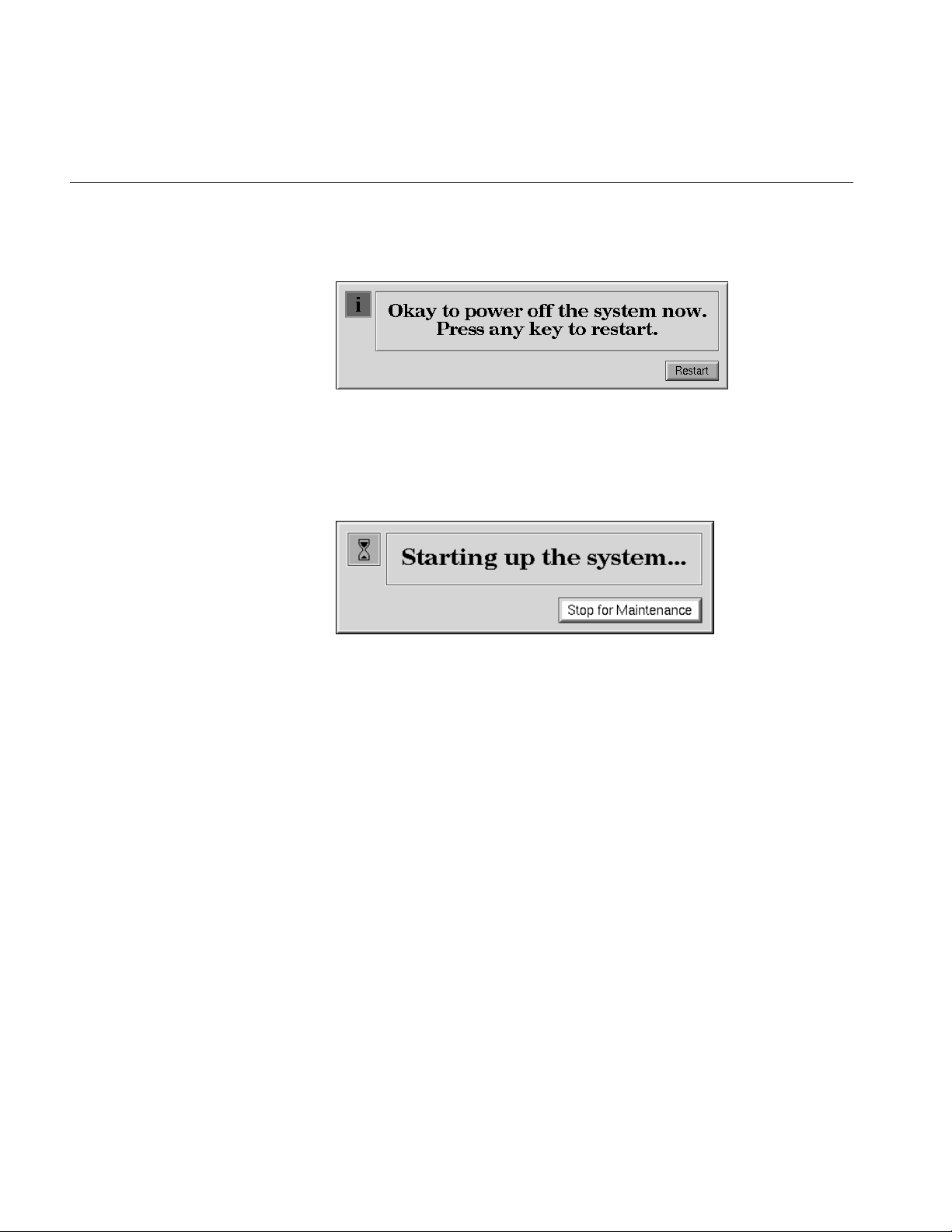
You see the message shown in Figure 1-2.
Figure 1-2 Okay to Power Off Notifier
■ Click the Restart button.
You then see the message shown in Figure 1-3.
Figure 1-3 Starting Up the System Notifier
■ Click on the Stop for Maintenance button. The System Maintenance
menu appears.
2. Press 5 on the keyboard, or click on the Enter Command Monitor icon on
the System Maintenance menu.
3. See what version of the PROM you have. At the >> prompt, type:
version
Then press <Enter>.
You see a line similar to this:
PROM Monitor SGI Version 5.0 Rev B5 IP24 Jul 15, 1994 (BE)
The date, “Jul 15, 1994” tells you the version of the PROM.
4
Checking the PROM Chip Version
• If your PROM is dated July 15, 1994 or later, you do not need to
replace the PROM chip. When installing the upgrade, skip
“Replacing the PROM in an Indy Workstation” on page 12, but
complete all the other installation steps.
• If your PROM is dated before July 15, 1994, you must replace the
PROM chip. Complete all the hardware installation steps.
4. After you have checked your PROM version, type exit to exit the
PROM monitor.
5. You see the System Maintenance menu again. It is safe to turn off your
Indy.
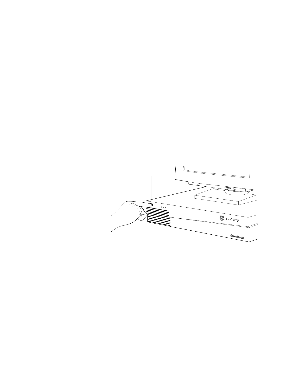
6. Turn off the power by pressing and releasing the power button on the
front of the Indy, as shown in Figure 1-4. The system powers off
automatically.
Power button
Figure 1-4 Turning Off the Indy Workstation
5
Chapter 1: Installing the Indy Presenter Hardware and Software
Removing the Top Cover
Follow these steps to remove the top cover of your Indy workstation.
Before removing any exterior cables, familiarize yourself with their location
so that you’ll find it easier when reconnecting them later.
Caution: Your monitor is very heavy. Have someone help you move it.
1. If the monitor is on top of the workstation, move it to one side.
2. Disconnect the black power cable and the monitor cable from the back
of the Indy workstation.
There are several other cables connected to the rear of the Indy chassis.
Disconnecting them is optional, however, if you do, you’ll have more
room to work with when removing the screws from the back panel.
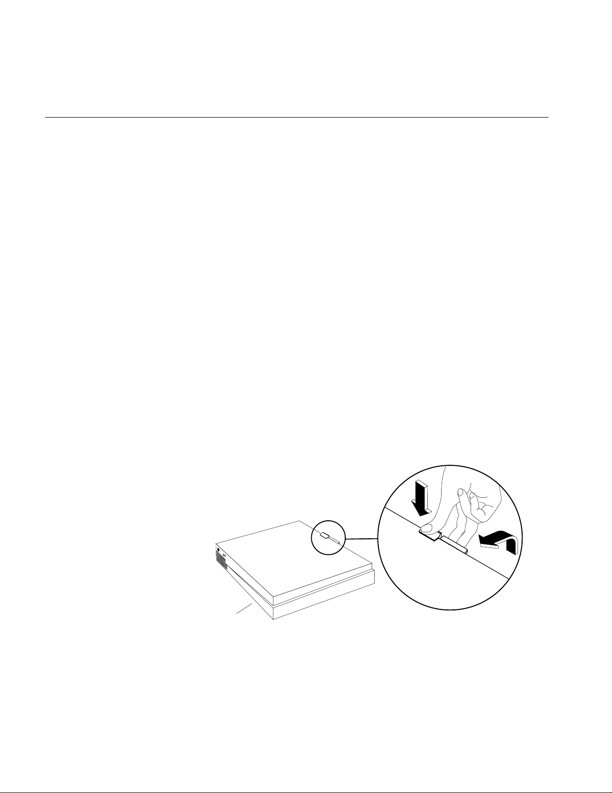
3. Facing the front of the Indy workstation, place your right thumb
against the lip at the back of the cover, and your second and third
fingers under the finger ledge, as shown in Figure 1-5.
4. Snap the cover loose by bracing your thumb against the lip and
pushing up the finger ledge with the second and third fingers, followed
by a firm push toward the front.
5. Slide the cover forward about one inch, tilt it up, and remove it.
Front
Figure 1-5 Removing the Top Cover From the Indy Workstation
6

Attaching the Wrist Strap
Attaching the Wrist Strap
Wear the wrist strap to prevent the flow of static electricity, which can
damage the components in the Indy workstation.
Caution: The components inside the Indy are extremely sensitive to static
electricity. Handle all chips and modules carefully, and wear the wrist strap
shipped with the upgrade package while replacing parts inside the system.
To attach the wrist strap, follow these steps:
1. Put the wrist strap over your wrist, making sure it is tight against your
arm.
2. Attach the alligator clip to a metal part of the Indy chassis.
7
Chapter 1: Installing the Indy Presenter Hardware and Software
Removing the GIO Option Board
To replace the PROM chip or to install either of the Indy Presenter adapter
boards, you must first remove any GIO option boards, if installed.
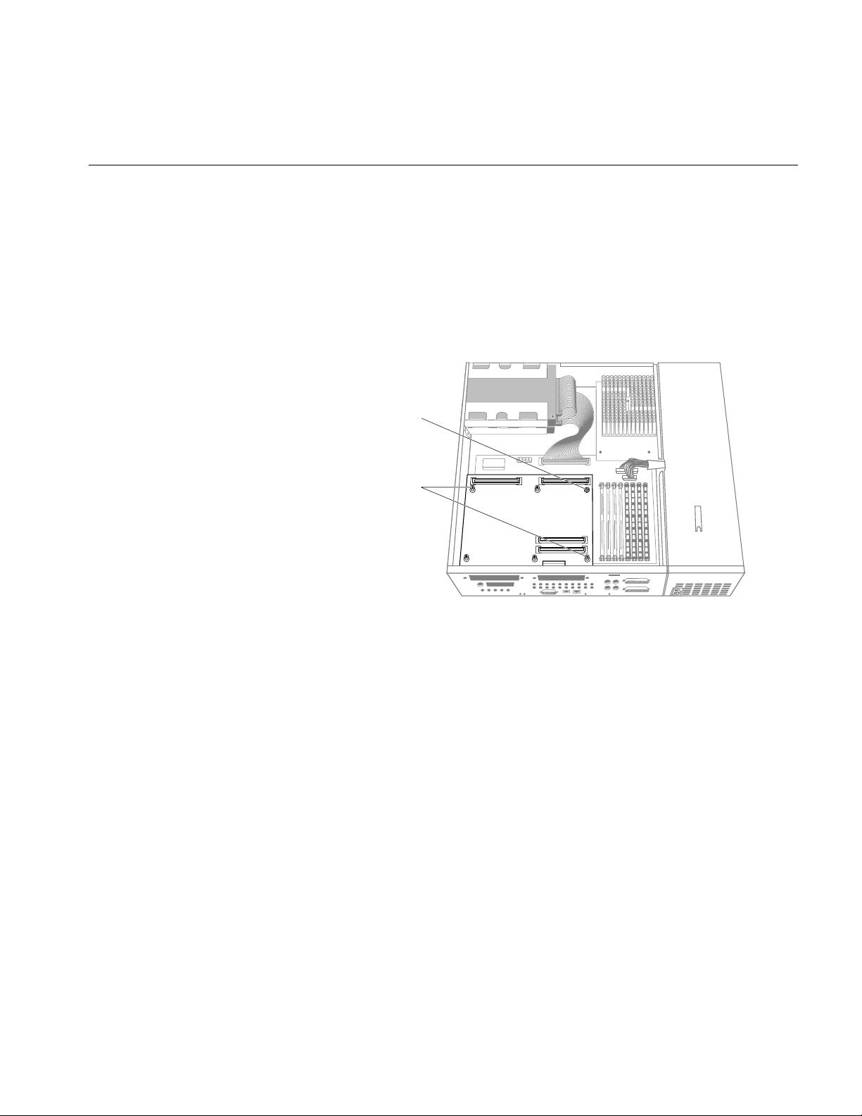
GIO option boards are located on top of the graphics board and can be
single-width, covering half of the graphics board, or double-width, covering
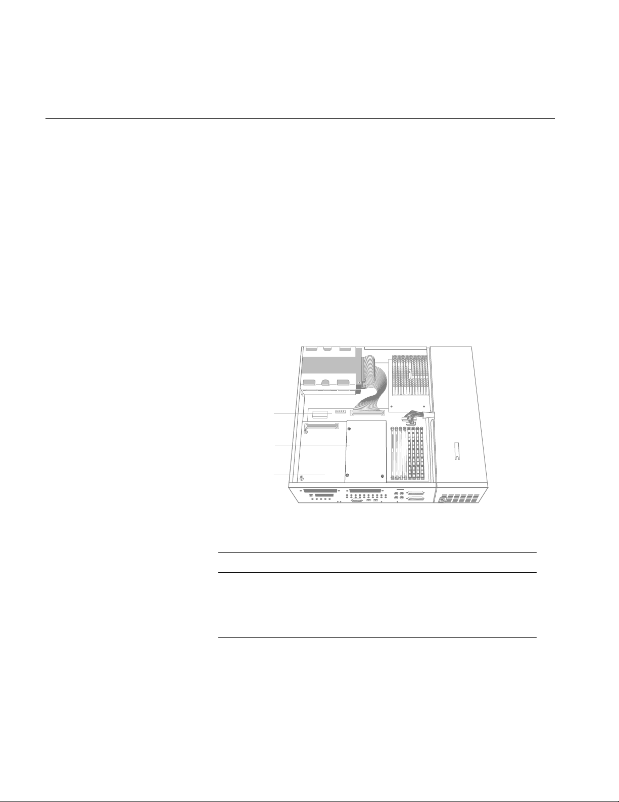
the entire graphics board. Figure 1-6 shows a single-width board. If there’s a
GIO board installed, your system will have three levels of boards: the system
board on the bottom, the graphics board in the middle, and the GIO board
on top.
To determine if you have a GIO option board installed, compare your system
to the one shown in Figure 1-6. Then follow the instructions below.
System board
Single-width
GIO board
Graphics board
Figure 1-6 Indy Workstation With Single-Width GIO Option Board
If your Indy workstation has: Then:
One or more GIO option boards
Go to step 1 on page 9.
installed
No GIO option boards installed Go to “Replacing the PROM in an
Indy Workstation” on page 12.
8
Removing the GIO Option Board
1. Locate the GIO option board, as shown in Figure 1-7.
Note: These instructions are for a single-width GIO option board. Use
the same steps to remove a double-width GIO option board. The only
difference is that there are more screws to remove on a double-width
board.
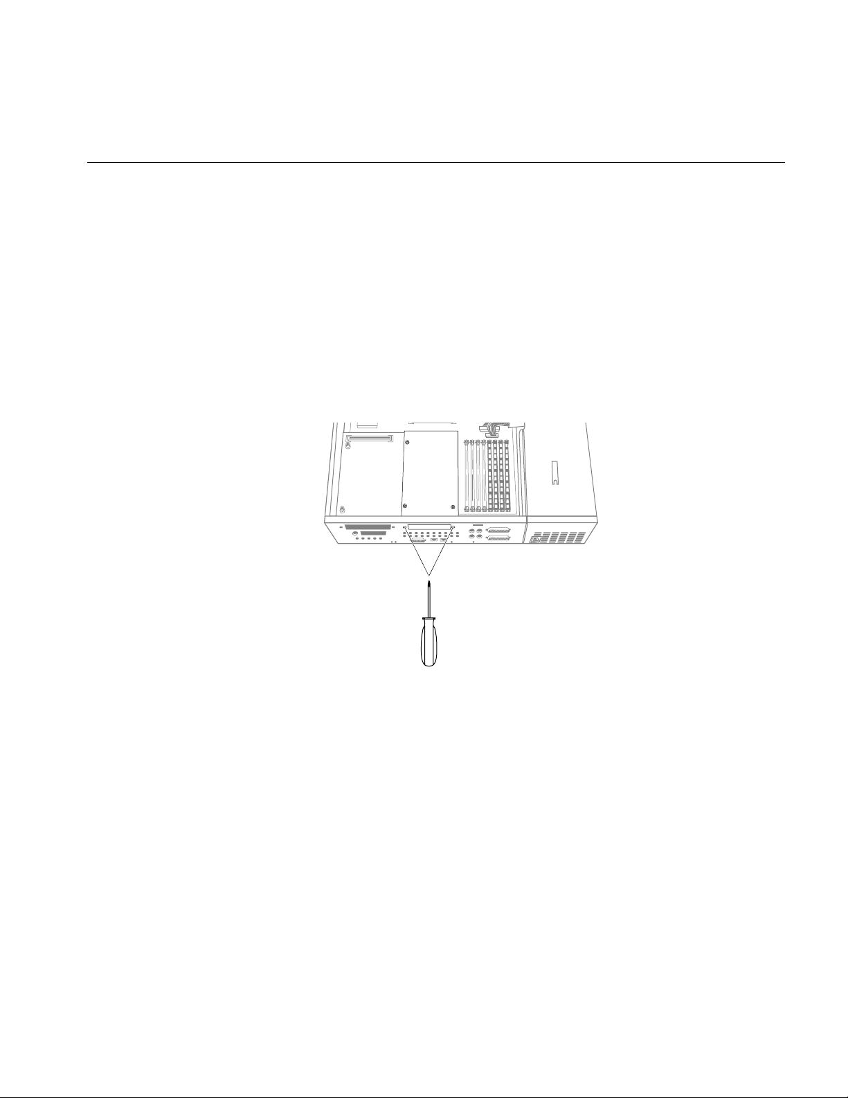
2. If there are external cables connected to the GIO option board’s I/O
connector on the rear of the workstation, disconnect them.
3. Using the Phillips screwdriver provided with this package, remove the
two screws from the GIO board connector on the rear of the
workstation, as shown in Figure 1-7.
Figure 1-7 Removing the Screws From the GIO Board Connector
9
Chapter 1: Installing the Indy Presenter Hardware and Software
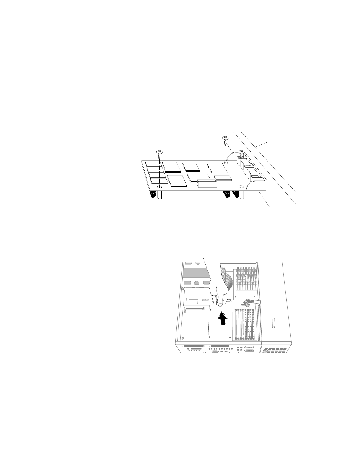
4. Using a Phillips screwdriver, remove the three screws that connect the
GIO option board to the graphics board, as shown in Figure 1-8.
Note: A double-width GIO option board has more than three screws
to remove.
Figure 1-8 Removing the Screws From the GIO option Board
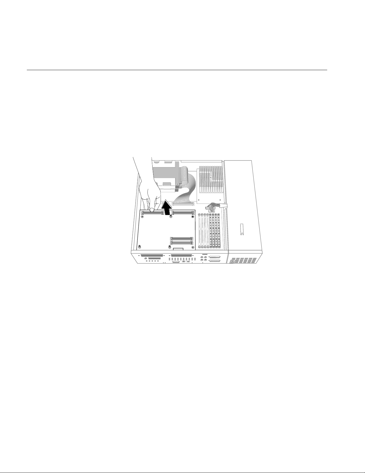
5. Disconnect the GIO board from the graphics board by grasping the GIO
board firmly and pulling it up, as shown in Figure 1-9.
Rear
10
GIO option board
Graphics board
Figure 1-9 Disconnecting the GIO Option Board

Removing the GIO Option Board
You are now ready to either replace the PROM chip, or to install the Indy
Presenter adapter board.
Follow the instructions in the table below.
If: Then:
You are replacing the PROM Go to “Replacing the PROM in an
Indy Workstation” on page 12.
You are not replacing the
PROM
Go to “Installing the Indy Presenter
Adapter Board” on page 23.
11
Chapter 1: Installing the Indy Presenter Hardware and Software
Replacing the PROM in an Indy Workstation
To reach the PROM chip on the system board, you must first remove the
graphics board.
Removing the Indy Graphics Board
Follow these steps to remove the graphics board:
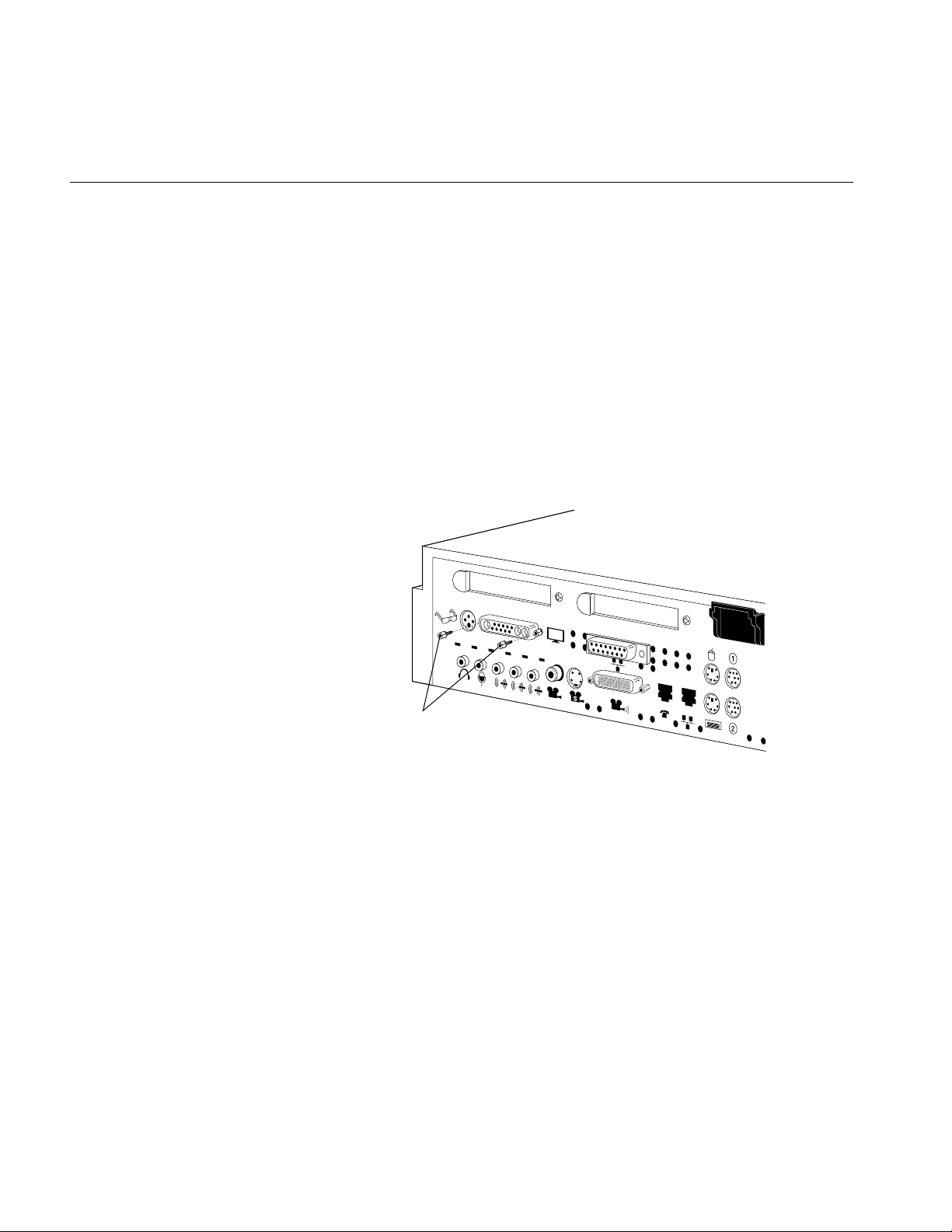
1. Use the open-ended wrench to unscrew the two hexnuts screws on
either side of the graphics board’s I/O connector on the rear of the
workstation. (See Figure 1-10.) The wrench is provided with this kit.
12
Hexnut screws
Figure 1-10 Removing the Hexnut Screws From the Rear Panel
Replacing the PROM in an Indy Workstation
2. Remove the following screws from the graphics board:
■ Use the open-ended wrench to unscrew the two standoff screws
(tall, hexagonal posts) from the graphics board. (See Figure 1-11.)
■ Use a Phillips screwdriver to remove one screw from the
graphics board.
Phillips screw
Standoff screws
Figure 1-11 Removing the Screws From the Graphics Board
13
Chapter 1: Installing the Indy Presenter Hardware and Software
3. Disconnect the graphics board from the system board, as shown in
Figure 1-12.
■ Grasp the board firmly on the side close to the system disk drive.
■ Pull up to disconnect the two connectors under the graphics board
from the sockets on the system board.
■ Lift the graphics board up and remove it.
14
Figure 1-12 Disconnecting the Graphics Board From the System Board
You are now ready to replace the PROM chip.
Replacing the PROM in an Indy Workstation
Replacing the PROM Chip
If your PROM chip is dated before July 15, 1994, follow the steps below to
replace it. (You should have already checked the version of your PROM chip
before shutting down and opening up the system. See “Checking the PROM
Chip Version” on page 3.)
Follow these steps to remove and replace the PROM chip.
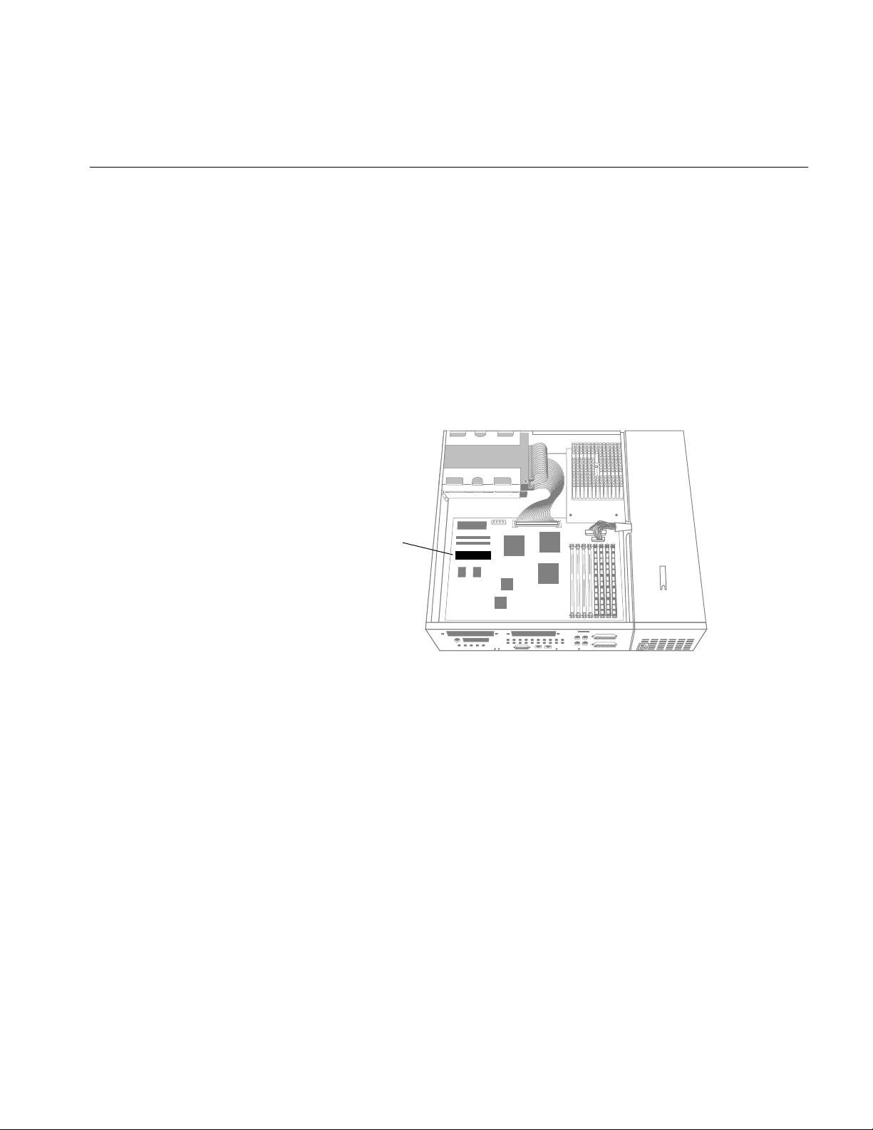
1. Locate the PROM chip on the system board, as shown in Figure 1-13.
PROM chip
Figure 1-13 Locating the PROM Chip on the System Board
Before removing the PROM chip, familiarize yourself with it. Note that it has
either a semicircular notch or a small, indented circle at the end facing the
memory SIMMs. You’ll use this notch or circle to orient the upgrade PROM
when you install it.
15
Chapter 1: Installing the Indy Presenter Hardware and Software
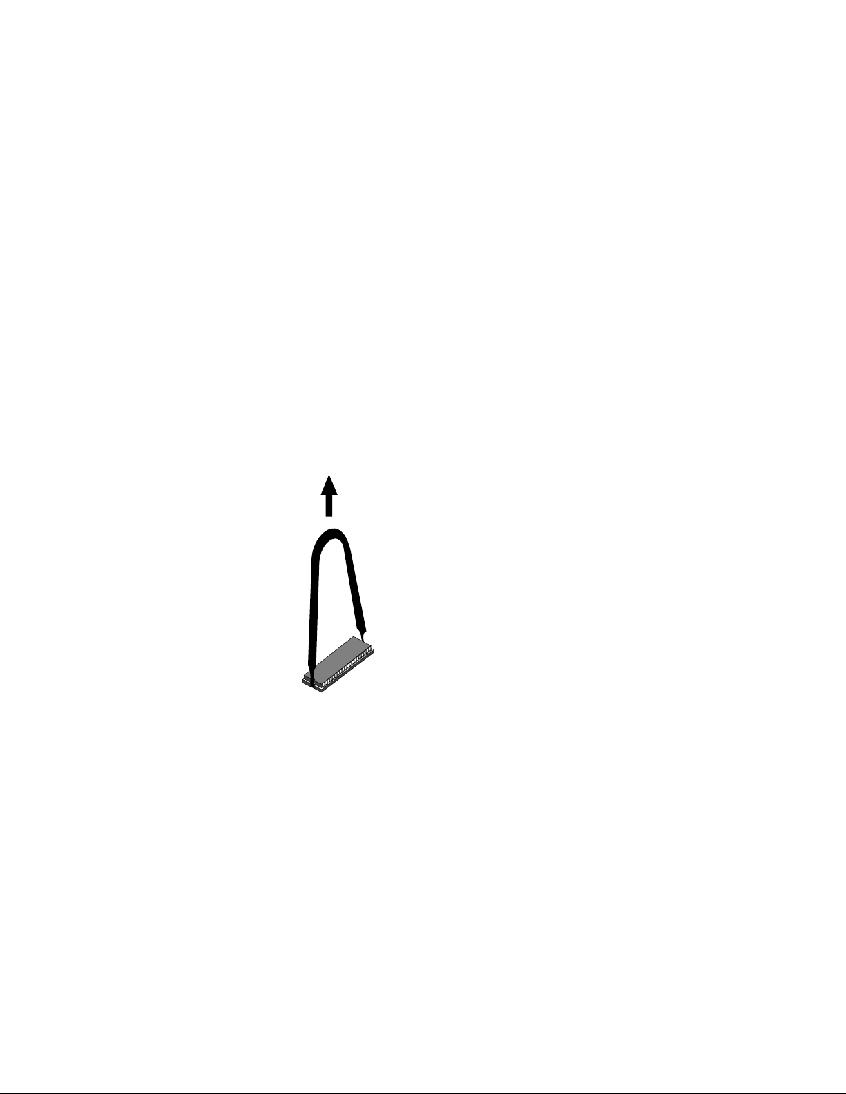
2. Remove the PROM chip from the system board.
The PROM chip is seated in a socket that is permanently attached to the
system board. You remove the chip with a chip removal tool, included
in this package. The tool looks like a pair of huge tweezers. When you
use the tool, be sure to insert it under the PROM chip itself, and not
under the socket.
■ Insert the chip removal tool between the PROM chip and the socket
on the board, as shown in Figure 1-14. Work the chip away from the
socket in a rocking motion, pulling up on one side of the chip and
then on the other side. It may be difficult to loosen.
■ Continue the rocking motion until the PROM chip is all the way out
of the socket.
16
Figure 1-14 Removing the PROM Chip

Replacing the PROM in an Indy Workstation
3. Install the new PROM chip.
■ Grasp the new PROM chip. Orient the PROM above the socket on
the system board so the end with the semicircular notch or small,
indented circle on the PROM chip lines up with the notch in the
socket. (See Figure 1-15.)
Caution: Make sure you line up the notch or the small circle on the
PROM chip with the notch in the socket. If you install the PROM
chip backwards, the system will not power on and you will damage
the PROM chip.
■ Line up all of the pins on the PROM with the corresponding holes
in the socket.
PROM chip
with notch
Notch
Figure 1-15 Lining Up the PROM Chip
PROM chip with
indented circle
Notch
17
Chapter 1: Installing the Indy Presenter Hardware and Software
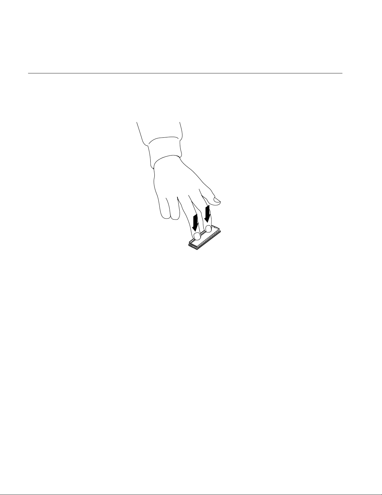
4. Once the pins are lined up, press down firmly on the top of the PROM
chip until it is seated in the socket, as shown in Figure 1-16.
18
Figure 1-16 Pressing the PROM Chip Into the Socket
5. Visually check to make sure that all the pins on the PROM are inserted
correctly in the holes on the socket and that the PROM is seated all the
way.
You are now ready to replace the graphics board.
 Loading...