


machine-service-no.
M16999 F
Indutherm order service
for consumables:
Tel.: +49 7203 9218-40
sales@indutherm.de
Indutherm
technical service
Tel.: +49 7203 9218-41
support@indutherm.de
INDUTHERM Erwärmungsanlagen GmbH
Brettener Straße 32
D-75045 Walzbachtal
Germany
Tel.: +49 (0)7203 9218-0
Fax: +49 (0)7203 9218-70
e-mail: info@INDUTHERM.de
Instruction Manual for
Vacuum Pressure Casting Machine
VC 400 LCD

Contents
Contents .......................................................................................................................... 2
1 Introduction ............................................................................................................. 3
1.1 General description of the VC400 ....................................................................... 3
1.2 Machine components .......................................................................................... 3
1.3 Technical data ..................................................................................................... 4
1.4 General information ............................................................................................. 5
2 Putting into operation .............................................................................................. 7
2.1 Set-up directions .................................................................................................. 7
2.2 Mains supply ........................................................................................................ 7
2.3 Cooling water ....................................................................................................... 7
2.4 Protective gas (Argon or Nitrogen) ...................................................................... 8
2.5 Vacuum ............................................................................................................... 8
2.6 Gas out ................................................................ ................................................ 8
2.7 Vacuum pump socket .......................................................................................... 8
2.8 RS232 Connector ................................................................................................ 8
3 Safety ..................................................................................................................... 9
3.1 Intended use ........................................................................................................ 9
3.2 Demands on staff, duty for utmost care ............................................................. 10
3.3 Protective measures .......................................................................................... 10
3.4 Safety marking ................................................................................................... 13
3.5 Safety advices ................................................................................................... 14
3.6 Residual risks .................................................................................................... 17
3.7 Behaviour in an emergency situation ................................................................. 17
4 Operation .............................................................................................................. 18
4.1 Operating elements ........................................................................................... 18
4.2 Casting .............................................................................................................. 23
4.3 Possible causes for dissatisfying casting results ............................................... 26
4.4 Configuration of flask ......................................................................................... 27
4.5 Granulating ........................................................................................................ 28
5 Consumable parts ................................................................................................ 29
5.1 Assembly drawing VC400 .................................................................................. 29
5.2 Consumables and spare parts list ..................................................................... 30
6 Service .................................................................................................................. 33
6.1 Troubleshooting ................................................................................................. 33
6.2 Diagram casting flasks without flange ............................................................... 34
6.3 Diagram casting flasks with flange .................................................................... 34
6.4 Maintenance ...................................................................................................... 35
6.5 Declaration of conformity ................................................................................... 36
7 Connection diagrams ............................................................................................ 38
8 Test result chart .................................................................................................... 41
9 Software documentation ....................................................................................... 42
86014010_04_OPERATING_MANUAL_VC400_LCD_GB.DOC 25.11.2016 KS page 2

Revision
date
document
index
topic
technical
responsible
30.09.13
-
first version
Schmidt
15.12.14
86014010_01
safety advice added
Schmidt
16.12.14
86014010_02
special function „automatic pressure start“
Schmidt
15.04.16
86014010_04
revised
RK
14.06.16
86014010_04
last corrections
RK
1 Introduction
1.1 General description of the VC400
With this vacuum pressure-casting machine, the melting charge is heated up by
induction under protective gas. The liquid metal is poured into evacuated, preheated
flasks for jewellery production (lost wax process) or is poured directly into the
granulating apparatus for the production of granules.
The special advantage of inductive heating is that the melting temperature is reached
rapidly, because the heat is directly generated in the metal and in the crucible. During
the melting process, the metal is thoroughly mixed by means of a magnetic field,
ensuring a homogenous mixing even when using new alloys. As the metal is poured
through the crucible bottom, only pure metal can reach the form, i.e. the die; whereas
contamination stays on the surface and can only cover the top of the cast.
Installing the thermocouple in the crucible allows an exact temperature measuring and
also the output of the unit is controlled in such a way that the set temperature remains
constant.
1.2 Machine components
The machine consists of separate units built into one casing:
1. Inside the casing, the following components are installed:
- microprocessor controlled induction generator F-type with
serial number F and 4 digits (Important for INDUTHERM!),
- medium frequency transformer,
- oscillation circuit capacities,
- pneumatic valves,
- pressure control for sealing pressure of sealing rod cylinder and
- pressure control for protection gas.
2. The front panel consists of:
- operating elements for the control of melting and casting cycles.
86014010_04_OPERATING_MANUAL_VC400_LCD_GB.DOC 25.11.2016 KS page 3

VC400 single phase
VC400 3 phase
Crucible volume
170 cm3 2.5 kg/Au
Flask
max. Ø 130 mm (5“) * 260 mm (10“) height
Crucible temperature
max. 1400 °C with type S thermocouple
Generator
INDUTHERM F type
Melting performance
3.5 kW
4.5 kW
Mains supply
1x230V/1x16A, 50 or 60 Hz
3x400V/3x16A, 50 or 60 Hz
Cooling water supply
2.5 - 5 bar/at least 200 l/h
2.5 - 5 bar/at least 200 l/h
Cooling water recoil
without pressure
Cooling water entry
temperature
15 – 25 °C
Room temperature
10 – 35 °C
Relative atmospheric
humidity
20 – 80 %
Protective gas supply
=>8 bar, pure N2 or pure Argon
Vacuum
0 - 20 mbar max., at least 21 m³/h
Weight
approx. 120 kg
Dimensions (width *
height * depth)
500 mm * 1450 mm * 810 mm
3. The casting unit consists of:
- water cooled inductor casing with inductor, crucible, insulation parts,
sealing rod device, thermocouple,
- water cooled bell,
- water cooled vacuum chamber,
- flask lift,
- vacuum chamber lift and
- granulating device (option).
1.3 Technical data
Those values marked with a * apply to the standard machine and can be modified on request.
86014010_04_OPERATING_MANUAL_VC400_LCD_GB.DOC 25.11.2016 KS page 4

1.4 General information
Safety information
In order to ensure a constant, ideal performance of the machine and to ensure safe
working conditions, the user is to observe the following safety measures:
The complete electrical wiring is to be performed only by qualified and specially
trained personnel.
Check the machine and the supply devices regularly on possible damages.
When opening cabinet/casings or when removing parts (exception: when this is
possible by hand), certain parts under electric power can cause danger. If opening
up the machine is necessary (before maintenance, change of machine settings,
repair or exchange of parts) the machine must be cut off the mains voltage. If
working on the opened machine is inevitable, only qualified trained personnel aware
of the danger caused hereby and aware of the relevant regulations may be
instructed to do this work.
Capacitors in the machine can still be charged even when the machine’s mains
supply is switched off.
When it seems that the machine can no longer be worked safely it has to be taken
out of production and secured against further unintentional use. The following
incidents indicate that safe working is no longer possible:
- the machine is visibly damaged
- the machine does not function
- uncommonly heavy wear from transportation
The safety valves placed inside the machine casing may not be removed, closed or
altered in any way.
As melted metal is processed with this machine (temperatures up to 1400 °C), the
utmost care and attention has to be applied when working with the VC400. The
following necessary safety clothing is principally to be worn:
- fireproof clothes,
- fireproof closed shoes,
- fireproof gloves and
- safety goggles.
Special caution is essential when working with graphite crucibles and graphite dies
because these are only visibly hot at temperatures above 500 °C!
In commercial enterprises the regulations for the prevention of accidents of the
relevant authority for electrical machinery are to be followed.
86014010_04_OPERATING_MANUAL_VC400_LCD_GB.DOC 25.11.2016 KS page 5

People with pacemakers must not be near the machine while it is running.
Trained responsible staff has to be supervised to work with this machine.
Use as determined/liability
This casting machine is designed and manufactured to comply with the latest technical
knowledge and according to approved safety regulations. When not putting into
operation correctly or not using the machine as determined, however, danger and
damages may occur. Therefore we suggest reading carefully and completely this
manual before putting the machine into operation and to follow the instructions given
therein:
This machine is only to be used for melting, casting and granulating of precious
metals normally used for the production of jewellery.
This machine may only be connected as mentioned in this manual. The mains
supply as well as in- and outgoing pressures are to be provided as stated on the
machine label.
This machine was designed for use in closed spaces (indoors) and may only be
used for the above-mentioned purpose.
Only original INDUTHERM consumable and spare parts are to be used.
The machine may not be modified in any way. Technical changes may only be
effected with INDUTHERM GmbH’s prior written permission.
Damages caused by disregard or false interpretation of the contents of this
instruction manual result in an immediate expiration of the machine guarantee.
This instruction manual is corresponding to the latest technical condition of the
machine when printed. Technical changes and fittings subject to change.
INDUTHERM GmbH cannot and will not take responsibility for any damages
resulting of the above mentioned.
This instruction manual may not even partially be reproduced (photocopy, micro
film, computer processing etc.) without prior written permission of INDUTHERM
GmbH.
86014010_04_OPERATING_MANUAL_VC400_LCD_GB.DOC 25.11.2016 KS page 6

2 Putting into operation
On delivery, immediately check if the machine is complete and if there are any
transportation damages. In the case of damages, please contact at once supplier or
forwarding agent.
2.1 Set-up directions
The machine should be placed on clean and dry ground. The ground should be even,
solid and level. The rear side of the machine must remain freely accessible to ensure
sufficient circulation of cooling air. The cooling air temperature must not exceed 35°C
and must not be contaminated. Only after all supply and connecting systems have been
connected, the machine may be put into operation.
2.2 Mains supply
Only trained personnel may connect the machine. Please pay attention to the nominal
voltage and frequency stated on the machine label. The voltage may differ +/- 10%
(maximum) from the nominal value. The mains supply must at least be furnished with a
16 A delay-action fuse. All lines (L1, L2, L3 and PE) must be connected correctly
2.3 Cooling water
Use two hoses with an inner ø of 8 mm for the cooling water. The water entry pressure
must be at least 2.5 bars and must not be more than 5 bars. The water drainage must
be without pressure. The water entry temperature must be above 15 °C and must not
exceed 25 °C. The concentration of lime in the water must not be more than 60 mg
CaO/l. The cooling water must not be contaminated.
The supply hose for the granulating apparatus (option) must have an inner ø of 8 mm
also, the draining hose an inner diameter of 19 mm.
Caution: As long as the crucible temperature is above 100 °C, the cooling water supply
must be open; otherwise the inductor insulation could be destroyed. In case the cooling
water supply stops while there is still a hot crucible inside the machine, the crucible
must be removed at once.

2.4 Protective gas (Argon or Nitrogen)
Purity to be no less than 99.95% must be used as protective gas. Use a compressed air
hose with an inner ø of 6 mm. The inlet pressure must be 8 bars. The machine will start
adding protective gas into the inductor housing at temperature higher the 500 °C.
2.5 Vacuum
When putting into operation, check the motor rotation direction (direction of arrow). Oil
level and air filter should be checked weekly. The first oil change should be done after
100 working hours. Later on, we recommend changing it regularly every 500 - 2000
working hours, depending on the working process, though at least every 6 months.
Recommended oil type: HD30 / SAE30.
The oil filter should be replaced on every second oil change. The pump should have a
minimum suction power of 21 m³/h and an end pressure of 2 mbar.
For more detailed information please refer to the instruction manual for the vacuum
pump.
The vacuum connection is through a suction hose with an inner diameter of 13 mm at
the rear side of the casing to the vacuum pump.
2.6 Gas out
Pressure release output. This output must be open all the time.
2.7 Vacuum pump socket
The vacuum pump socket is for 3 phase vacuum pumps (3 * 400 V AC) with a
maximum load of 1.5 kVA. During installation the rotation of the vacuum pump must be
checked. Otherwise the pump might be destroyed.
2.8 RS232 Connector
At this connector our modem article no. 71000320 or the serial cable article no.
50500060 can be connected.
86014010_04_OPERATING_MANUAL_VC400_LCD_GB.DOC 25.11.2016 KS page 8

3 Safety
3.1 Intended use
Operational safety of the plant for vacuum casting is only guaranteed at intended use.
The vacuum casting machine serves exclusively for melting and pouring of metals and
alloys. The specified temperature ranges must be complied with.
Every other use of the overall plant or parts is considered as not intended.
Unauthorized modifications of the plant are prohibited because of reasons for safety!
Intended use includes reading, knowing and obeying the operating instructions. That
also contains observing of servicing and maintenance regulations.
Set up, operation and maintenance is only allowed to be carried out by trained qualified
personal that has read and understood all documents.
The plant may affiliate only to the specified media. Supply voltage and input
respectively output pressure have to be observed to the given device labeling
accordingly.
The machine has been developed for use in enclosed spaces and for the above
mentioned application.
Only original INDUTHERM consumables and spare parts are admitted for operation.
It is not allowed to change or vary the system in any way. Technical changes need
explicit written approval of INDUTHERM.
Predictable abuse:
warming of human body parts on hot surfaces.

3.2 Demands on staff, duty for utmost care
Work on and with the machine is allowed to be accomplished by reliable, trained and
instructed staff only. Responsibilities for the separate sections have to be regulated
clearly which include operation, preparation, service and repair.
Only authorized personnel may act at the system.
The machine may never be operated by personnel under influence of reflex diminishing
medicine or people not able to work because of illness or disorder.
Running of the system has to be always supervised by trained staff.
Personnel which has to be trained und introduced to this job or within in the course of
vocational training may work only under permanent observation of a person
experienced with the machine.
Work on the electrical equipment is only allowed for workers skilled in the field of
electricity.
The instruction manual has to be freely disposable at the location of the system. The
employees have to know the storage place.
Every person working at the system has to read and apply the instruction manual
especially the safety advices. The personnel has to read and understand the chapters
referring to safety aspects for the particularly components of the machine. Please read
before beginning the work.
Please control the personnel for paying attention to all facts of safety and danger
prevention.
3.3 Protective measures
This operator’s guide contains all important advices to operate the system secure.
Basic prerequisite for safe dealing and trouble-free running of this system is the
knowledge of fundamental safety advices and industrial safety rules.
In commercial facilities you have to regard the accident prevention regulations of the
professional association for electrical systems and tools.
The internal regulations of industrial safety are to be observed.
86014010_04_OPERATING_MANUAL_VC400_LCD_GB.DOC 25.11.2016 KS page 10

Caution!
Wear always for every process step the right protective gear.
Caution!
Safety equipment protect from unintentional access of the staff
to danger spots. They prevent possible injuries. Never
manipulate the safety devices!
3.3.1 Concept of safety
Objective is the safety
of the staff against injuries
of the system against damage or standstill
of the environment against endangering
The list of actions taken:
deployment of protective equipment like covers and main-switch with emergency
stop function,
water-cooled inductor housing,
duty of wearing protective clothing with gloves and safety goggles (PPE),
affix safety markings on the installation and
create safety advices in the manual.
3.3.2 Protective gear
Protective gear (PPE) includes:
heat-resistant clothes,
heat-resistant, closed shoes,
heat-resistant protective gauntlets protecting artery,
face guard.
3.3.3 Safety equipment
The safety of the machine is only guaranteed if all safety equipment is proper installed
and working proper. Don’t use the system without the safety equipment!
Disassembling safety equipment is only allowed with locked main-switch. Install every
part of the safety equipment after repair. Perfect function has to be checked.
86014010_04_OPERATING_MANUAL_VC400_LCD_GB.DOC 25.11.2016 KS page 11

Caution!
With the emergency stop function you can stop the machine
in critical moments of health hazard. You help to diminish
potential consequences of injury.
safety
marking
meaning
safety
marking
meaning
warning of dangerous
electrical voltages
wear heatresistant
safety clothing
warning of hot
surfaces
wear heat-resistant
protective gauntlet
gloves protecting
artery
forbidden for persons
with pacemaker
wear face guard
wear protective
shoes
Advice
Keep the safety markings always clean. Replace the markings
if they aren’t recognizable. Observe the warnings and
commands. Don’t expose yourself careless to dangerous
situations.
3.3.4 Main switch with emergency stop function
It is allowed to start the machine or operation only with proper emergency stop function.
Don’t manipulate the emergency stop equipment.
Don’t obstruct the way to the emergency stop equipment.
3.3.5 Safety markings placed on the machine casing
A necessary condition for safe dealing with and undisturbed running of the machine is
the knowledge of safety instructions and industrial safety regulations.
On the front of the machine casing the following safety markings are attached.
86014010_04_OPERATING_MANUAL_VC400_LCD_GB.DOC 25.11.2016 KS page 12

Danger!
Death, serious body injury or substantial property damage will
result if proper precautions are not taken.
Warning!
Death, serious injury or substantial property damage can
result, if proper precautions are not taken.
Careful!
Minor personal injury can result if proper precautions are not
taken.
Danger!
Property damage can result, if proper precautions are not
taken.
Information/advice
Here you get information and advices to carry out the following
activities effective and safe.
3.4 Safety marking
The following signal words are used in this document which are associated with safety
markings for presentation of possible dangerous situations.
86014010_04_OPERATING_MANUAL_VC400_LCD_GB.DOC 25.11.2016 KS page 13
Danger!
Danger because of strong electromagnetical fields
(induction). For persons with pacemaker it is not
allowed to approach or to be near to the machine.
Warning!
Risk of burning on hot surfaces and hot metal
(until ~ 2100 °C). Wear always personal protective
equipment when you work with the machine.
Utmost caution during using graphite crucibles and
graphite molds. The heat of these parts is only
visible when the temperatures are over 500 °C.
Warning!
Maintenance and servicing of the machine only when the
system is disconnected from the mains supply. (Pull out mains
plug).
Danger!
Danger of burning. When you melt the metal without the supply
of protective gas a jet flame or a blow up can happen in the
moment you open the inductor chamber.
At temperatures exceeding 500 °C always use protective gas.
Use argon or nitrogen exclusively.
3.5 Safety advices
Check always the condition of the system before you switch on the system. Examine
the supply pipes and insulations if there are leaks and damages. Operate the system
only if it is in proper and faultless shape.
Operate the system never:
if there are malfunctions,
if it is showing damage or
after heavy transportation stress.
The system has to be constantly controlled when running to be able to recognize and
avoid dangerous situations. The system may not run if it is unsupervised.
Do never change, remove or close the safety valves inside the machine.
86014010_04_OPERATING_MANUAL_VC400_LCD_GB.DOC 25.11.2016 KS page 14

Danger!
Danger for the eyes.
Always place the gold coated foil for eye protection against
thermal radiation on top of the inspection window of the
crucible chamber.
In addition wear safety goggles suitable for welding operations.
Danger!
Danger because of touching parts conducting
voltage.
Work on the electrical equipment is only allowed for
authorized qualified staff.
Access to the electrical distribution box is only
allowed for authorized qualified staff with key or tool.
Work on the electrical equipment is only allowed
when the system is disconnected from power supply
(pull out power plug).
The capacitors can retain their charge even after
deactivation of the system.
Keep electrical distribution boxes closed
continually.
No work must be carried out on parts conducting
high voltage.
Remove loose connections.
Replace immediately damaged, scorched or
slightly burned cables. Perform work only when
mains plug is pulled out.
Cables may not wedge in or rather squeezed.
Cables have to be laid in a way that they not
become a tripping hazard or can be not
damaged.
Danger!
Threat of health injury by escape of medias from damaged
hoses. Danger of system damages.
Remove loose connections. Replace damaged hoses
immediately. Perform work only when mains plug is pulled
out.
Hoses may not wedge in or rather squeezed. Hoses have
to be laid in a way that they not become a tripping hazard
or can be not damaged.
86014010_04_OPERATING_MANUAL_VC400_LCD_GB.DOC 25.11.2016 KS page 15

Danger!
At crucible temperatures over 100 °C the cooling water supply
must be switched on. If it is not turned on, the inductor will be
destroyed. If cooling water supply fails, the heating system
immediately is turned off. Inspect the system for damage
before putting back into operation again.
Danger!
Lethal injuries happen because of false transport by forklift
truck.
Pay attention of the right attachment of the means of
transportation, otherwise the system can fall from forklift
truck. The system must be lifted from the side only,
because the center of gravity is located in front and
towards the upper third of the machine.
With too small dimensioned or forks adjusted too narrowly
there is danger for the system to fall from the means of
transportation.
Wear appropriate personal protective equipment. (PPE).
Move the system only by skilled personnel qualified for
transportation jobs.
For damages resulting from non-compliance of regulations in
transit there is no assertion possible for warranty claims.
Warning!
Risk of burns because of leaking molten metal.
Warning!
Risk of injury.
Make pressure leading system parts depressurized before you
carry out servicing.
Warning!
Risk of slip on the floor around the installation in case
someone had spilled lubricant or solvent.
Clean the floor from dirt immediately! Dispose cleaning tissues
in the particular collecting boxes.
86014010_04_OPERATING_MANUAL_VC400_LCD_GB.DOC 25.11.2016 KS page 16

Caution!
Observe regulations for the mains supply written
from the responsible electric power supply
company, the association VDE and the local electric
power station.
Inappropriate connecting can lead to injuries and
damages of the machine.
risk characterisation
risk reduction
Health risk for persons with
cardiac pacemaker who
approach the running system.
Instruct people.
Burn injury on hot surfaces or
hot molten metal.
Teach people.
Wear personal protective gear.
Jet flame or explosion when
opening the lid of the melting
chamber in case of melting
without protective gas.
Always melt with protective gas
at temperatures above 500 °C.
Tilting and toppling of the
system due to improper
transportation.
Consider shipping instructions.
3.6 Residual risks
3.7 Behaviour in an emergency situation
The personnel working at the facility must be trained about the behaviour in an
emergency situation.
All persons who are working with the machine must be informed of the possibility of
rapid standstill of the plant.
86014010_04_OPERATING_MANUAL_VC400_LCD_GB.DOC 25.11.2016 KS page 17

Top level =
Actual program
status
Bottom level =
Selectors for
different values
4 Operation
4.1 Operating elements
4.1.1 VC400 screen when starting the machine
On the top level shown:
378 °C == actual temperature
1000 °C == set temperature
‘1.46 bar crucible == actual crucible pressure (-1 to 1.5 bars)
‘-1.00 bar flask == actual flask pressure (-1 to 0 bars)
‘4.5 kW == actual heating power in kW
1 Program == active program with name "18 ct ye b"
On the bottom level shown:
Temp - == lower the set temperature even within a program
Temp + == rise the set temperature even within a program
Program - == go the next program one place below
Program + == go the next program one place higher (program 1)
Program setup == level to modify the selected program (here program 0)

Top level =
Actual program
status
Bottom level =
Selectors for
different values
4.1.2 VC400 modify program screen
On the top level shown:
0001 program == selected program to modify
1000 °C temperature == set temperature inside the crucible
0100 % heating power == heating power from 5-100%
00.8 s Turbo pressure start == time between confirming the “manual cast” start
1.50 bar turbo pressure
maximum == casting pressure maximum value
On the bottom level shown:
Λ == go to the value one step higher (here “Turbo Pressure Start”)
V == go to the value one step lower (change Label)
- == lower the value (here set Turbo pressure to 1.49 bar)
+ == rise the value (not possible)
Main page == go back to main page
If you go with the cursor down the VC400 allows you to modify the program name to
your needs (e.g.: 18ct ye b = 18 carat yellow gold and big pieces.
and turbo pressure rise
86014010_04_OPERATING_MANUAL_VC400_LCD_GB.DOC 25.11.2016 KS page 19

VC400 /
VC500
Material
Bronze
Yellow
gold 14k
(with
zinc)
Yellow
gold 18k
Aluminium
Brass
Silver
935
Test
Crucible
Graphite
Graphite
Graphite
Graphite
Graphite
Graphite
Graphite
Program No.
10
11
12
13
14
15
18
Temperature
°C
1150
1060
1080
740
1080
1000
0010
Heating
power
%
0100
0100
0100
0100
0100
0100
100
Turbo
pressure
start
s
00.8
00.8
00.8
00.8
00.8
00.8
00.8
Turbo
pressure
maximum
bar
1.00
1.00
1.00
1.00
1.00
1.00
0.50
Label
Bronze
YG 585
750/YG
Aluminum
Brass
935/Ag
InduTest
4.1.3 Pre-set casting programs
4.1.4 VC400 modify system parameter
If you start from the start page and you press“ Program setup“ for 5 seconds you get
access to the system parameter.
On the top level shown:
000:00002 == selected parameter == 000
value of parameter 00002: equals two == type N thermocouple
If you press “Λ” you get access to the parameter 001 and higher.
By pressing “+” you change the value of parameter 000 to 3
86014010_04_OPERATING_MANUAL_VC400_LCD_GB.DOC 25.11.2016 KS page 20
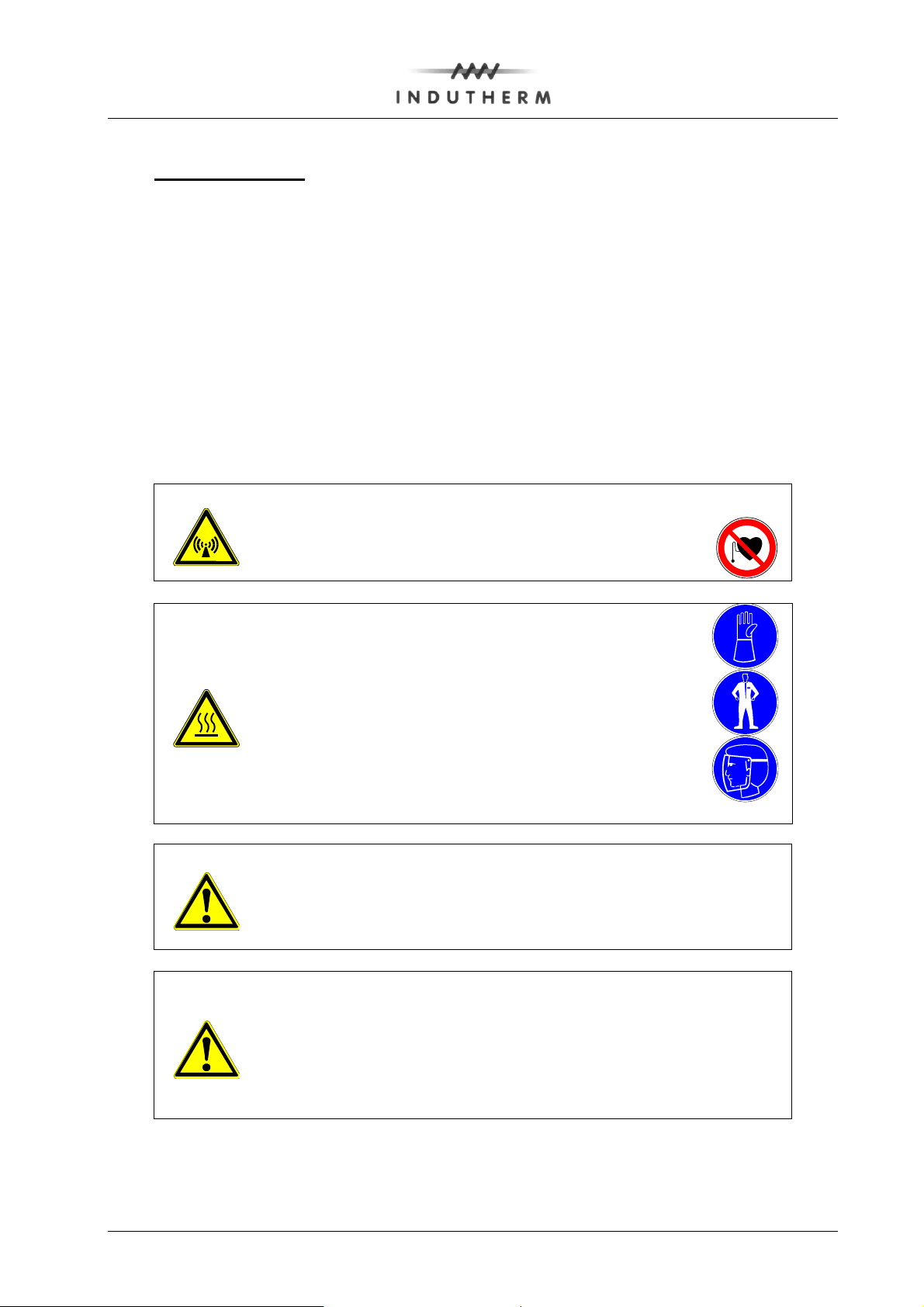
4.1.5 VC400 service info page 1
If you press now „Service“-button you see the software ID, generator number and
machine number.
If you press service again you get to the next page.
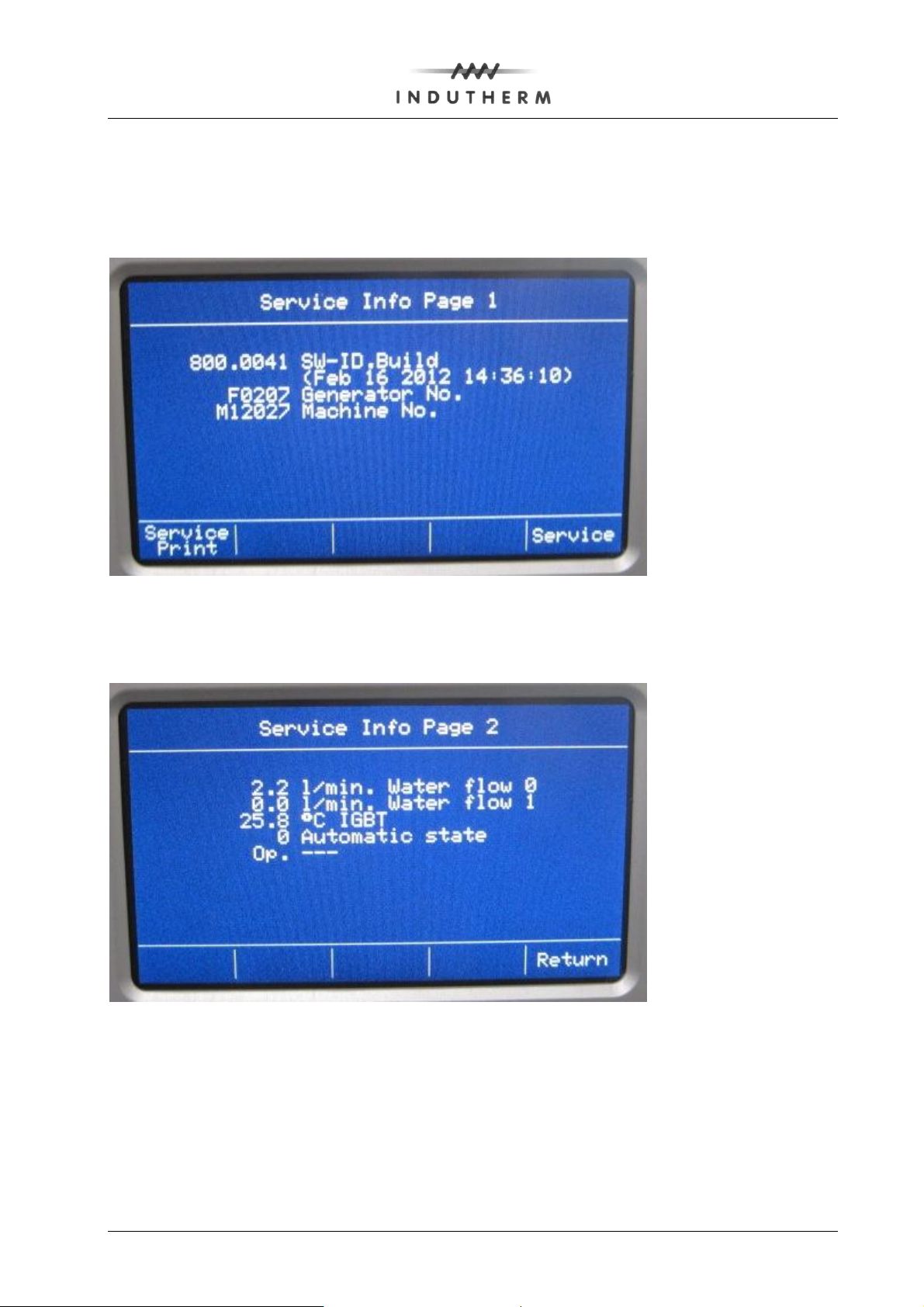
4.1.6 VC400 service info page 2
Here you see the water flow, the generator temperature and other features.
86014010_04_OPERATING_MANUAL_VC400_LCD_GB.DOC 25.11.2016 KS page 21

Generator area:
Generator Stop
==
stops heating ( if not operating in program )
Generator Starts
==
starts heating
Generator +
==
increases output power of generator
Generator -
==
decreases output power of generator
PGM Start
==
downloads the program settings into memory and
starts program
S.- rod dynamic
==
movement of sealing rod as long as the button is
pressed
S.- rod static
==
movement of sealing rod from close to open and
opposite
Turbo Press.
==
adds overpressure to the inductor housing as long
as the button is pressed (up to "Turbo pressure
maximum")
Vacuum pump
==
switches vacuum pump on and off
Crucible:
Use this rotary switch to select between standard pressure,
vacuum or over-pressure in the crucible area.
Normal No vacuum, no over-pressure in the crucible
area, only flow of protective gas (a very frequently used
casting mode!)
Pressure With this mode, the inductor housing is sealed,
which means that the pressure depends on the amount of
protection gas that is used. When less gas is used than is
exhausted under the flask, there is an under-pressure.
Vacuum In this mode, the inductor housing is directly
connected with the vacuum pump, so that the maximum
possible vacuum is created. This enables, for example, to
melt the metal under vacuum.
4.1.7 VC400 buttons below display
Additional operating elements
86014010_04_OPERATING_MANUAL_VC400_LCD_GB.DOC 25.11.2016 KS page 22

Flask (rotary switch):
By using this rotary switch, select if the flask is to be
evacuated or ventilated.
Locked- Standard position to add or remove the flask
into the vacuum chamber.
Vacuum- After putting in place the flask, the vacuum is
turned on. Approx. 20 seconds afterwards the casting
process can be started.
Release- Having this position the vacuum chamber will be
filled with protective gas.
Flask:
When this switch is in upper position, the pneumatic cylinder
installed in the vacuum chamber rises so that the flask can
be taken out easily.
When putting in a larger flask, the cylinder should be in high
position.
When now turning the FLASK switch, the flask moves back
into the vacuum chamber.
Vacuum chamber:
When this pneumatic switch is in upper position, the vacuum
chamber is lifted, so that – when the chamber is closed – the
whole casting area is sealed. When moving the switch down,
the vacuum chamber moves to lower position and can then
be moved aside.
Main switch:
The machine is turned on/turned off by turning this switch.
- Granulating tank (option):
Regulate the water stream in a way that the water is in motion, but does not
sprinkle.
After the granulating process the metal can be taken out by lifting out the insert.
4.2 Casting
Before starting check crucible, sealing rod and crucible insulation for dirt
residues/possible damages. It is recommended to use a vacuum cleaner to clean the
entire inductor. The metal filter (left of the sealing rod) should be taken out and cleaned
with compressed air.
A suggestion for a general casting process (vacuum in flask, normal pressure in
crucible):
1. Open cooling water, compressed air and protective gas supplies.
86014010_04_OPERATING_MANUAL_VC400_LCD_GB.DOC 25.11.2016 KS page 23

2. Switch on vacuum casting machine and vacuum pump.
3. Grind in the sealing rod into the crucible bottom (rotating movement)
4. Set the desired melting program.
5. Select 'normal’ with the valve ‘crucible’ (standard selection: normal-pressure).
If pressure or vacuum is selected, the vacuum chamber must be closed with your
flask already inside.
6. Start program with the button “PGM start”.
7. The generator will start to preheat the crucible to almost set-temperature.
8. If the crucible reaches the set temperature, fill the melting charge into the
crucible.
9. Shortly before the set-point temperature is reached, set in the flask without delay
and switch on vacuum with the valve ‘Flask’.
10. The machine will show now “confirm manual cast”.
11. Now change the rotary switch “crucible” to the desired position. For overpressure
to the position “12 o’clock”.
12. Take a final look at your metal if the metal surface meets your requirements.
13. The machine will show now “confirm turbo pressure end” and count the cooling
time (here 26 seconds gone).
86014010_04_OPERATING_MANUAL_VC400_LCD_GB.DOC 25.11.2016 KS page 24

14. Release the vacuum with the valve ‘flask’.
If the crucible was put under over- or under-pressure, also release it with the
valve ‘crucible’ to ‘normal’ position.
15. Lower the vacuum chamber with the valve ‘chamber lift’ and swing out the
chamber.
Now the flask can be removed.
- Before or just after opening the sealing rod, the pressure at the top of the flask
can be changed with the valve ‘crucible’ to normal-pressure, under-pressure or
over-pressure.
A new casting cycle can start, beginning with step 3.
If casting process is finished:
1. Press "Generator stop".
2. Vacuum pump should run at least 5 minutes after last casting to remove humidity.
86014010_04_OPERATING_MANUAL_VC400_LCD_GB.DOC 25.11.2016 KS page 25

1.
Casting temperature is too low/too high.
2.
Flask temperature is too low/too high.
3.
Configuration of flask is disadvantageous ("branches" too thin or too close to
the top).
4.
Flask is not totally heated up (at least 2 hours on end temperature).
5.
Flask was slaked too early/too late.
6.
Contamination in the alloy (for example "bad copper").
7.
Material was not pre-alloyed/granulated.
8.
Investment for flask was bad/old
9.
Eventually not enough protective gas or the gas had water inclusions.
10.
Wrong crucible position (different crucible temperatures).
11.
Not enough vacuum inside the vacuum chamber (at least - 0.9 bar for good
casting).
12.
Vacuum was turned on too late/turned off too early.
13.
Contamination in the investment because of wax residues (steam out flasks).
14.
Graphite contamination (use ceramic insert or crucible of better graphite quality).
Please note that INDUTHERM cannot be held responsible for dissatisfying casting
results.
4.3 Possible causes for dissatisfying casting results
Dissatisfying casting results can have various causes and, depending on the material,
can have various effects. The following "check list" is to help find the different causes:
86014010_04_OPERATING_MANUAL_VC400_LCD_GB.DOC 25.11.2016 KS page 26

4.4 Configuration of flask
86014010_04_OPERATING_MANUAL_VC400_LCD_GB.DOC 25.11.2016 KS page 27

Remove container.
Dump the water.
Remove material.
4.5 Granulating
Before starting check crucible, sealing rod and crucible insulation for dirt
residues/possible damages. It is recommended to use a vacuum cleaner to clean the
entire inductor. The metal filter (left of the sealing rod) should be taken out and cleaned
with compressed air.
For the production of granules, a crucible with a casting opening of 2 mm in diameter is
recommended.
A suggestion for the granulating process:
1. Open cooling water, compressed air and protective gas supplies.
2. Fill the tank with water until overflow is reached.
3. Turn on the vacuum casting machine.
4. Set the desired melting temperature and start the heating (button “Start”).
Protective gas will be added at temperatures above 500 °C automatically.
5. When the set-point-temperature is reached, carefully grind in the sealing rod into
the crucible bottom (rotating movement) and fill in the material.
6. When the material is melted, regulate the water inlet through the spray nozzles in
a way that the water is in motion, but does not splash.
7. Depending on the alloy, the metal should be kept on temperature for a few
minutes or be stirred manually.
8. Open sealing rod.
9. If the crucible is not complete empty remove remaining material with the turbo
pressure button.
If you want to continue with the same alloy restart at 5. or
10. Stop heating.
11. Move granulating tank to the left side and remove inlet.
86014010_04_OPERATING_MANUAL_VC400_LCD_GB.DOC 25.11.2016 KS page 28

Attention:
The numbers like C008 are placeholder for the
position in the machine. The article number to order
this piece is 8 digits and listed in your machine
specific order list G16999_00.pdf.
5 Consumable parts
5.1 Assembly drawing VC400

first digit
machine
service
number
function
(here
vacuum
casting)
crucible
outside
dimension
vacuum
chamber
inside
index
G
15033
VC
68
169
00
SI sintering
parts
GR parts to
granulate
name
function
where to find
optional spare
parts
list shows parts for:
e.g. high temperatures
and special alloys
replacement
parts
parts that might go
defective during the
years of operation
accessory parts
parts that might help
you to operate your
machine
5.2 Consumables and spare parts list
At following side the spare parts list for this machine will start.
INDUTHERM is now using only machine specific spare parts lists, which contain all the
information for your machine.
The name is encoded. One example could be G15033_VC_68_169_00
If spare parts are replaced by new parts, the index will be incremented. This ensures
that you always receive the latest version of consumables and spares. To be sure that
the data is correct, INDUTHERM and our sales partners or end customers must work
together.
G13xxx show you only the spare part that wears off. In the web shop you will find other
lists that might help you:
Genuine INDUTHERM parts are clearly marked with our 3D hologram.
86014010_04_OPERATING_MANUAL_VC400_LCD_GB.DOC 25.11.2016 KS page 30

Attention!
To order parts or to receive your order list as PDF file please contact
your local sales partner.
E-mail
consumables@indutherm.de
Telephone no
+49-7203-9218-40.
Attention!
Please understand that INDUTHERM has to support more than 3000
machines. We cannot sort spare parts only with your customer name.
We always need your machine service number, to send you the
correct spare part.
If you open the accessory part list, you will see this screen:
For direct customers, please contact our order department
86014010_04_OPERATING_MANUAL_VC400_LCD_GB.DOC 25.11.2016 KS page 31

This page will be replaced with G16999_00
(16999= machine no.).
_00 is version of spare parts list. Changes will be
done with _01, _02, due to customer’s requirements.
Example: G16999_01 (second version of the list for
machine 16999).
86014010_04_OPERATING_MANUAL_VC400_LCD_GB.DOC 25.11.2016 KS page 32

6 Service
6.1 Troubleshooting
Only trained personnel should open the machine.
The machine cannot be turned on:
- when there is no mains supply.
The heating cannot be turned on:
- when there is no cooling water supply,
- when there is no compressed air supply,
- when there is no protective gas supply,
- when thermocouple is not in place or defective and
- when generator is running hot.
For other error codes and warnings, see chapter_Software_documentation software
documentation.
Incorrect temperature indication:
- thermocouple was not programmed correctly on temperature control
(in this case generator can be stopped)!
Low generator output:
- nominal value of temperature control too low.
Problems with pressure in the bell:
- bad flask gaskets (replace gaskets, lower gasket: use silicon, upper gasket: use
graphite),
- clean flask flange and
- error with vacuum supply (when using vacuum).
Problems with vacuum in the flask:
- bad flask gaskets (replace gaskets, lower gasket: use silicon, upper gasket: use
graphite),
- clean flask flange,
- clean vacuum pump filter and
- vacuum supply not in order.
86014010_04_OPERATING_MANUAL_VC400_LCD_GB.DOC 25.11.2016 KS page 33

vacuum area
force of the air
pressure
force of the
overpressure
Possible problems of losing vacuum
1.) O-Ring vacuum chamber is
not OK.
2.) Flask top surface is not flat
enough.
3.) Silicon ring is missing or
defect.
4.) Flask lift cylinder is not in “up”
position.
5.) By using overpressure on the
crucible area you need 8 bars
air pressure. With 6 bars
pressure the flask will move
down and the vacuum will be
lost.
6.) Flask has cracks.
vacuum
area
force of the
overpressure
Possible problems of losing vacuum
1.) Flask flange is not flat enough.
2.) Silicon ring is missing or
defect.
3.) Flask has cracks.
6.2 Diagram casting flasks without flange
6.3 Diagram casting flasks with flange
86014010_04_OPERATING_MANUAL_VC400_LCD_GB.DOC 25.11.2016 KS page 34

6.4 Maintenance
A routine check/regular cleaning of the following is necessary: (Caution: disconnect the
machine first!):
Daily (before casting):
1. Remove thermocouple, sealing rod, crucible and insulation materials, carefully
clean inductor housing with a vacuum cleaner. Before reinstalling the above
parts, check those and replace if necessary.
2. Caution: The “sealing rod cylinder” must not be placed on lowest position when
sealing rod is in place. A sealing up of the casting hole is not guaranteed in this
case. If problems occur, check sizes of sealing rod, graphite ball, crucible and
crucible bottom insulations!
3. Clean metal filter placed left of sealing rod.
Weekly:
1. Lubricate threads of sealing rod holder (top) with high temperature grease.
2. Clean vacuum pump filter and check oil level/change oil. Recommended oil type:
HD30/SAE30.
Every 4 month:
1. Check vacuum pump filter and oil separator filter of vacuum pump.
Annually:
Depending on the water quality, the cooling system should be cleaned with 25 %-citric
acid. The cooling system should be treated with this acid for approx. 1 hour. Then clean
the system thoroughly with pure water and check on eventual leakages.
1. Tighten all electric wirings, especially those for power current.
2. Tighten all connections of water-cooling, pneumatic systems and protective gas.
86014010_04_OPERATING_MANUAL_VC400_LCD_GB.DOC 25.11.2016 KS page 35

6.5 Declaration of conformity
86014010_04_OPERATING_MANUAL_VC400_LCD_GB.DOC 25.11.2016 KS page 36

86014010_04_OPERATING_MANUAL_VC400_LCD_GB.DOC 25.11.2016 KS page 37

7 Connection diagrams
86014010_04_OPERATING_MANUAL_VC400_LCD_GB.DOC 25.11.2016 KS page 38

86014010_04_OPERATING_MANUAL_VC400_LCD_GB.DOC 25.11.2016 KS page 39

86014010_04_OPERATING_MANUAL_VC400_LCD_GB.DOC 25.11.2016 KS page 40

6
5
4
3
2
1
Material
Quantity
Type of cast
pieces
Crucible
temperature
Flask
temperature
Casting mode
(standard, vacuum,
over-pressure)
Flask size
Investment
Particularities
Result
Test date
8 Test result chart
Attention: On our new Internet page
http://www.indutherm.de/webshop
you can find examples how to troubleshoot errors.
9 Software documentation
The software documentation INDUTHERM article no. 86380000 with the error and
warning codes start on the next pages. For the F generator the software starts with 80000
xx = software index.
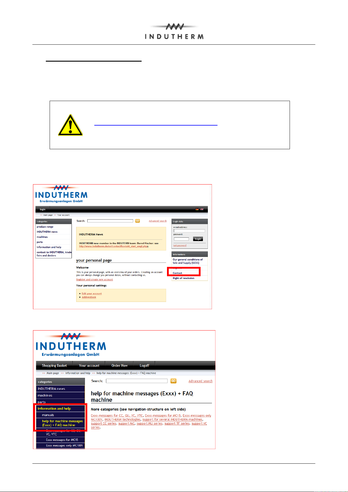
Before you can do so, you need to apply for a login. Only with the serial number we can
give you complete access. Click contact form and send it to us.
Then we will send you the login information’s. At the subdirectory "Help for machine
messages", you will find support documents.
86014010_04_OPERATING_MANUAL_VC400_LCD_GB.DOC 25.11.2016 KS page 42
 Loading...