

industrie technik TH-xxxSx1 Series User Manual
EN
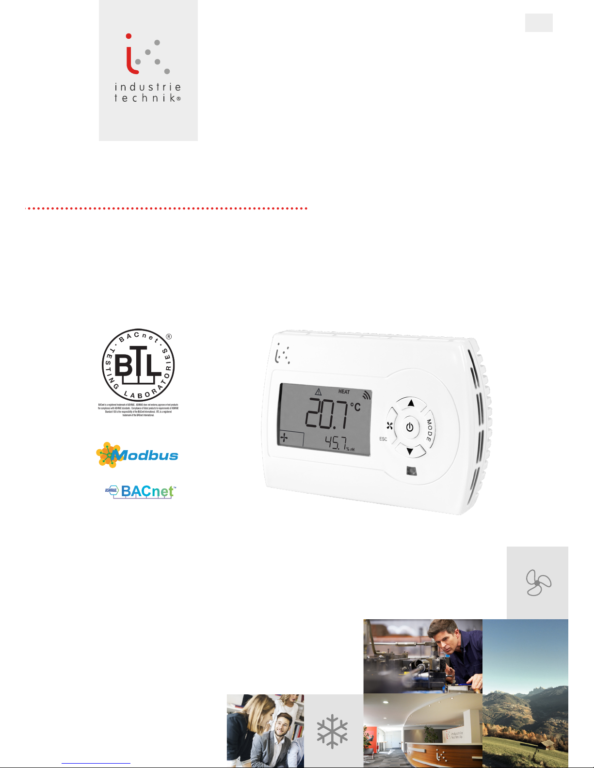
ROOM CONTROLLER
EVOLUTION
SERIES TH-xxxSx1
USER MANUAL

2/126
1. Technical features 10
2.
Code selection 10
3.
Display, keyboard and icons 11
4.
Quick access parameter setting 12
Keyboard lock: 12
Switch on and off 12
Setpoint setting 12
Fancoil operating mode 13
MODE button functionality 13
5.
Date and time setting (Model TH-xxCSx1) 15
6.
TIME ZONES operation and setting
(Model TH-xxCSx1) 15
7.
TIME ZONE duplication (Model TH-xxCSx1) 17
8.
Manufacturer parameter setting
(level 1 password) 18
9.
Installer parameter setting (level 2 password) 20
10.Digital and analogue input logic 24
Digital inputs 24
Analogue inputs 25
11.
Regulation sensor(s) 28
12.
Automatic season changeover
with water sensor (M01=2 or 5) 28
13.
Frost protection 28
14.
Working setpoint, ECONOMY mode
and HOLIDAY mode 29
15.
Timer extension mode 31
16.
Fancoil with EC motor
(models TH-0xxSx1, TH-1xxSx1, TH-2xxSx1) 31
EC motor automatic speed control logic
with on/off outputs 31
EC motor automatic speed control logic
with 0..10 V modulating outputs 32
17.
Fancoil with 3 speed on-off motor
(models TH-2xxSx1, TH-3xxSx1, TH-4xxSx1) 33
3 speed on-off motor speed control logic
with on/off outputs 33
3 speed on-off motor speed control logic
with 0...10V modulating outputs 33
18.
Manual speeds and ventilation
maintenance with no control 34
19.
Fan boost 34
20.
Minimum thermostat 34
21.
Destratication cycle 35
22.
Dirty lter 35
23.
Window contact 35
24.
Summertime changeover 35
25.
Sensor AI3 used as input 0...10V 35
26.
Outputs forced via Modbus 36
27.
Alarms 37
28.
Resetting the default parameters 39
29.
Control with EC motor (Model TH-0xxSx1) 40
HEATING mode (M01=0) 40
Wiring diagram 40
HEATING/HEATING mode (M01=1) 41
Wiring diagram 41
2 PIPE HEATING/COOLING mode with
AUTOMATIC SEASON CHANGEOVER (M01=2): 42
2 PIPE HEATING/COOLING mode with
SEASON CHANGEOVER by CONTACT (M01=3): 42
2 PIPE HEATING/COOLING with
SEASON CHANGEOVER by PARAMETER (M01=4): 42
Wiring diagram 43
2 PIPE HEATING/COOLING
+ ELECTRIC RESISTANCE mode with
AUTOMATIC SEASON CHANGEOVER (M01=5): 44
2 PIPE HEATING/COOLING
+ ELECTRIC RESISTANCE mode with
SEASON CHANGEOVER by CONTACT (M01=6): 44
2 PIPE HEATING/COOLING
+ ELECTRIC RESISTANCE mode with
SEASON CHANGEOVER by
PARAMETER (M01=7): 45
Wiring diagram 47
4 PIPE HEATING/COOLING mode (M01=8) 48
Wiring diagram 48
4 PIPE HEATING/COOLING mode
+ ELECTRIC RESISTANCE (M01=9) 49
Wiring diagram 49
TABLE OF CONTENT
AB Industrietechnik srl | Via Julius Durst, 70 | 39042 BRESSANONE (BZ) Italy | +39 0472/830626 | info@industrietechnik.it | industrietechnik.it

3/126
COOLING mode (M01=10) 50
Wiring diagram 50
COOLING/COOLING mode (M01=11) 51
Wiring diagram 51
30.
Regulation (Model TH-1xxSx1) 52
HEATING mode (M01=0) 52
Wiring diagram 52
HEATING/HEATING mode (M01=1) 53
Wiring diagram 53
2 PIPE HEATING/COOLING mode with
AUTOMATIC SEASON CHANGEOVER (M01=2): 54
2 PIPE HEATING/COOLING mode with
SEASON CHANGEOVER by CONTACT (M01=3): 54
2 PIPE HEATING/COOLING with
SEASON CHANGEOVER by PARAMETER (M01=4): 54
Wiring diagram 55
2 PIPE HEATING/COOLING
+ ELECTRIC RESISTANCE mode with
AUTOMATIC SEASON CHANGEOVER (M01=5): 56
2 PIPE HEATING/COOLING
+ ELECTRIC RESISTANCE mode with
SEASON CHANGEOVER by CONTACT (M01=6): 56
2 PIPE HEATING/COOLING
+ ELECTRIC RESISTANCE mode with
SEASON CHANGEOVER by
PARAMETER (M01=7): 56
Wiring diagram 58
4 PIPE HEATING/COOLING mode (M01=8) 59
Wiring diagram 60
4 PIPE HEATING/COOLING mode
+ ELECTRIC RESISTANCE (M01=9) 61
Wiring diagram 62
COOLING mode (M01=10) 63
Wiring diagram 63
COOLING/COOLING mode (M01=11) 64
Wiring diagram 64
31.
Regulation with EC motor (Model TH-2xxSx1) 65
HEATING mode (M01=0) 65
Wiring diagram 65
HEATING/HEATING mode (M01=1) 66
Wiring diagram 66
2 PIPE HEATING/COOLING mode with
AUTOMATIC SEASON CHANGEOVER (M01=2): 67
2 PIPE HEATING/COOLING mode with
SEASON CHANGEOVER by CONTACT (M01=3): 67
2 PIPE HEATING/COOLING with
SEASON CHANGEOVER by PARAMETER (M01=4): 68
Wiring diagram 69
2 PIPE HEATING/COOLING
+ ELECTRIC RESISTANCE mode with
AUTOMATIC SEASON CHANGEOVER (M01=5): 70
2 PIPE HEATING/COOLING
+ ELECTRIC RESISTANCE mode with
SEASON CHANGEOVER by CONTACT (M01=6): 70
2 PIPE HEATING/COOLING
+ ELECTRIC RESISTANCE mode with
SEASON CHANGEOVER by
PARAMETER (M01=7): 71
Wiring diagram 73
4 PIPE HEATING/COOLING mode (M01=8) 74
Wiring diagram 74
4 PIPE HEATING/COOLING mode
+ ELECTRIC RESISTANCE (M01=9) 75
Wiring diagram 76
COOLING mode (M01=10) 77
Wiring diagram 77
COOLING/COOLING mode (M01=11) 78
Wiring diagram 78
32.
Control with 3 speed ON/OFF motor
(Model TH-2xxSx1) 79
HEATING mode (M01=0) 79
Wiring diagram 79
2 PIPE HEATING/COOLING mode with
AUTOMATIC SEASON CHANGEOVER (M01=2): 80
2 PIPE HEATING/COOLING mode with
SEASON CHANGEOVER by CONTACT (M01=3): 80
2 PIPE HEATING/COOLING with
SEASON CHANGEOVER by PARAMETER (M01=4): 80
Wiring diagram 82
COOLING mode (M01=10) 83
Wiring diagram 83
AB Industrietechnik srl | Via Julius Durst, 70 | 39042 BRESSANONE (BZ) Italy | +39 0472/830626 | info@industrietechnik.it | industrietechnik.it

4/126
33. Regulation (Model TH-3xxSx1) 84
HEATING mode (M01=0) 84
Wiring diagram 84
HEATING/HEATING mode (M01=1) 85
Wiring diagram 85
2 PIPE HEATING/COOLING mode with
AUTOMATIC SEASON CHANGEOVER (M01=2): 86
2 PIPE HEATING/COOLING mode with
SEASON CHANGEOVER by CONTACT (M01=3): 86
2 PIPE HEATING/COOLING with
SEASON CHANGEOVER by PARAMETER (M01=4): 86
Wiring diagram 88
4 PIPE HEATING/COOLING mode (M01=8) 89
Wiring diagram 90
COOLING mode (M01=10) 91
Wiring diagram 91
COOLING/COOLING mode (M01=11) 92
Wiring diagram 92
34.
Regulation (Model TH-4xxSx1) 93
HEATING mode (M01=0) 93
Wiring diagram 94
HEATING/HEATING mode (M01=1) 95
Wiring diagram 95
2 PIPE HEATING/COOLING mode with
AUTOMATIC SEASON CHANGEOVER (M01=2): 96
2 PIPE HEATING/COOLING mode with
SEASON CHANGEOVER by CONTACT (M01=3): 96
2 PIPE HEATING/COOLING with
SEASON CHANGEOVER by PARAMETER (M01=4): 96
Wiring diagram 98
2 PIPE HEATING/COOLING
+ ELECTRIC RESISTANCE mode with
AUTOMATIC SEASON CHANGEOVER (M01=5): 99
2 PIPE HEATING/COOLING
+ ELECTRIC RESISTANCE mode with
SEASON CHANGEOVER by CONTACT (M01=6): 99
2 PIPE HEATING/COOLING
+ ELECTRIC RESISTANCE mode with
SEASON CHANGEOVER by
PARAMETER (M01=7): 99
Wiring diagram 103
4 PIPE HEATING/COOLING mode (M01=8) 104
Wiring diagram 105
COOLING mode (M01=10) 106
Wiring diagram 106
COOLING/COOLING mode (M01=11) 107
Wiring diagram 107
35.
USB connection 108
36.
Jumper settings 108
37.
Modbus (for versions TH-xMxSx1) 109
Default parameters reset via MODBUS 114
Clock setting via MODBUS 115
MODBUS communications alarm 115
MODBUS connection diagram 116
38.
BACnet (for versions TH-xBxSx1) 117
BACnet connection diagram 117
BACnet protocol implementation
conformance statement 118
Product description 118
BACnet Standardized Device Prole (Annex L) 118
List of all BACnet Interoperability
Building Blocks Supported (Annex K) 118
Segmentation Capability 118
Standard Object Types Supported 119
Data Link Layer Options 120
Device Address Binding 120
Networking Options 120
Network Security Options 120
Character Sets Supported 120
BACnet signals 121
Analogue inputs 121
Analogue values 121
Binary inputs 122
Binary values 123
Multistate values 124
Device 125
39.
Electrical connection 126
40.
Dimensions 128
41.
Installation instructions 128
AB Industrietechnik srl | Via Julius Durst, 70 | 39042 BRESSANONE (BZ) Italy | +39 0472/830626 | info@industrietechnik.it | industrietechnik.it

5/126
AB Industrietechnik srl | Via Julius Durst, 70 | 39042 BRESSANONE (BZ) Italy | +39 0472/830626 | info@industrietechnik.it | industrietechnik.it

6/126
TH room controller
1. Technical features
Power: 110...230 V AC ±10%, 50/60 Hz
Power consumption: max 1.3W
Operating temperature: 0...50°C
Display: backlit LCD display
Inputs: 2 potential free contacts
2 or 3 NTC10K sensors
USB for conguration and software updates
Outputs: 3 analogue outputs 0...10V (RL > 10K) depending on model
5 SPST relays, 250V AC, 3A (AC1) depending on model
Communications: Modbus RTU or BACnet B-ASC depending on model
Temperature reading range: -15...90°C
Dimensions: 128 x 80 x 55.5 mm
Installation: 3 module ush-mounted box
Protection class: IP30, class 2
CE standard conformity: EN 60730-1, EN 61000-6-3, EN 61000-6-1
2. Code selection
Room controller
TH
- x x x
S
x 1
Version:
1 digital output + 3 analogue outputs + 3 analogue inputs
2 digital outputs + 2 analogue outputs + 3 analogue inputs
3 digital outputs + 1 analogue output + 3 analogue inputs
3 digital outputs + 2 analogue outputs + 2 analogue inputs
5 digital outputs + 0 analogue outputs + 3 analogue inputs
0
1
2
3
4
Communications:
Without bus
Modbus
Bacnet
S
M
B
Clock:
Without clock
With clock
S
C
Internal sensor:
Temperature
Temperature + humidity
T
H

7/126
3. Display, keyboard and icons
%rH
485
°C
°F
set
HEAT
COOL
M
O
D
E
%rH
485
°C
°F
set
%
HEAT
COOL
ESC
M
O
D
E
%rH
485
°C
°F
set
%
HEAT
COOL
ESC
M
O
D
E
ESC
M
O
D
E
%rH
485
°C
°F
set
HEAT
COOL
M
O
D
E
Display A
%rH
485
°C
°F
set
%
HEAT
COOL
ESC
M
O
D
E
Display B
On/Off
ashing
Timer extension on
on
Clock setting
Economy function on
General alarm
Communications alarm
Parameters menu
Working season
Filter dirty alarm
Cooling on
Frost protection on
Heating on
Electric resistance on
Holiday mode
Fancoil speed
%rH
485
°C
°F
set
%
HEAT
COOL
ESC
M
O
D
E
Display C
Time zone number with status
Keyboard
On/Off, navigation and conrm key
Change setpoint, navigation and value entry keys
ESC
Speed type key and ESC in navigation
M
O
D
E
Manual season or occupation changeover key or operating mode
(see “MODE button functionality” page 9)
8/126
4. Quick access parameter setting
The controller provides the following functions with a simple button press:
• Switch on and off
• Setpoint setting
• Fancoil operating mode
• MODE button functionality
The MODE button can be assigned one quick access function and two normal access functions, depending on parameter I44
(see “MODE button functionality” page 9)
I44=0: season changeover (if it is local, for 2 pipe systems)
I44=1: timer extension.
I44=2: operating mode (without clock, with time program, holiday)
• Keyboard lock:
To lock the keyboard, press simultaneously buttons
ESC
M
O
D
E
, script LK appears on display for one second.
It is then not possible to access parameters if a key is pressed, script LK appears on display for one second.
To unlock the keyboard, simultaneously buttons
ESC
M
O
D
E
, script NLK appears on display for one second.
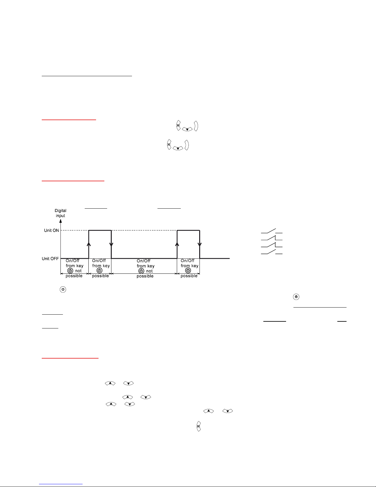
• Switch on and off
Switching on and off can be done in two ways: with an external contact or manually If one of the digital contacts is congured as “Remote On/Off”(M03=1 or M05=1) or one of the sensors is used as a digital input congured as “Remote On/Off”
(M07=4 or M09=4 or M11=4), the device can be switched off remotely by positioning the contact appropriately.
On this case the display A shows OFF and the display B shows rem if keyboard is not locked or Lrem if keyboard is locked.
Example for digital input 1 (M03=1):
Unit ON=
(M04=0)
Unit OFF= (M04=0)
Unit ON= (M04=1)
Unit OFF= (M04=1)
If the device is switched on by an external contact, it is however manually possible to switch on the device by pressing
button
until ON or OFF is displayed.
When the device is switched off by an external contact, it is not possible to switch it on with button
.
If the device is off, all outputs are deactivated except heating outputs in case of frost protection (see “13. Frost protection”
page 24).
If external contact is not used as remote on/off, when unit is switched off manually, the display A shows OFF and the dis-
play B shows nothing if keyboard is not locked or Lc if keyboard is locked.
• Setpoint setting
Based on parameter I52 value(CONFORT function), it is possible to modify directly the setpoint if I52=0 or to set only a
variation of ±3°C [±5°F] if I52=1. On the last case, this offset is added to the setpoint I07, I08, I09. This function is used
when it is necessary that the setpoint is not directly accessible to users.
With I52=0 pressing the or button, the value of actual setpoint is shown corresponding to setpoint I07 (for heating mode M01=0..7) or I08 (for cooling mode M01=2..7,10,11) or I09 (for 4 pipes operating mode).
The “set” icon ashes. With the or button it is possible to modify the value; the new value is automatically saved.
With I52=1 pressing the or button, the value of offset to apply to current setpoint is displayed.
The icon “°C” or “°F” is ashing based on actual unit. With the or button it is possible to modify the value; the
new value is automatically saved.
To exit the setting menu, wait for 4 seconds or press button
ESC
9/126
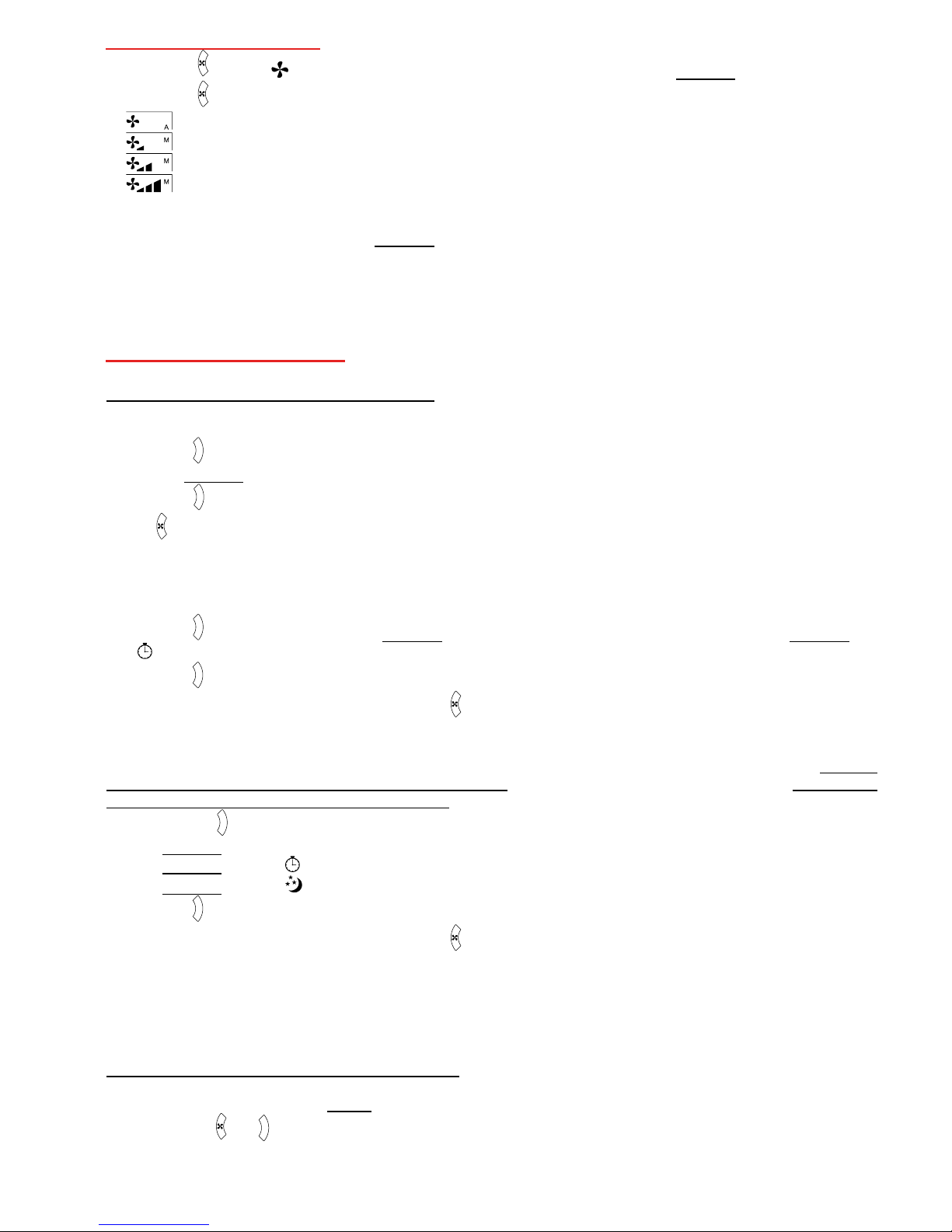
• Fancoil operating mode
Press button
ESC
, the icon ashes with the indication of the fancoil operating mode on display B.
Press button
ESC
one or more times to select the fan operating mode:
AUtO=automatic control,
SPE1=control with speed 1,
SPE2=control with speed 2,
SPE3=control with speed 3.
The value is automatically saved.
To exit the menu, wait for 4 seconds until display B stops ashing.
• MODE button functionality
To access quick functions of the MODE button:
If I44=0 (local season selection setting for 2 pipe systems: M01=4 or M01=7)
Press button
M
O
D
E
, the “HEAT” icon ashes (for heating) or “COOL” (for cooling) based on the actual setting and the same
appears on display B.
Press button
M
O
D
E
to change the settings. The value is automatically saved. To exit the menu, wait for 4 seconds or press
button
ESC
.
If I44=1 (timer extension setting)
The timer extension function extends operation with the base setpoint excluding the economy function and the “not occupied holiday” function for a time corresponding to parameter I47.
Press button
M
O
D
E
, the script noOC ashes on display B (to stop the timer extension if started) or script OC on display B and
icon
ashes (to activate the timer extension)
Press button
M
O
D
E
to change the settings. The value is automatically saved.
To exit the menu, wait for 4 seconds or press button
ESC
.
If I44=2 (operating mode setting)
The operation mode setting selects the control mode, either excluding or including the time program (see “6. TIME
ZONES operation and setting (Model TH-xxCSx1)” page 11), or in “not occupied holiday” mode (see “14. Working
setpoint, Economy mode and holiday mode” page 25).
Press the button
M
O
D
E
, the following script ashes:
nOrM on display B (for control without time zones) or
tiMB on display B and icon
(for control with time zones) or
HOLY on display B and icon
(for control in “not occupied holiday” mode).
Press button
M
O
D
E
one or more times to select the control mode. The value is automatically saved.
To exit the menu, wait for 4 seconds or press button
ESC
.
To access the other functions of the MODE button:
■ If the quick access mode of the MODE button is set to: Local season changeover (I44=0), to access other functions,
press buttons
ESC
and
M
O
D
E
together to enter the menu for changing the timer extension function and the operating mode:
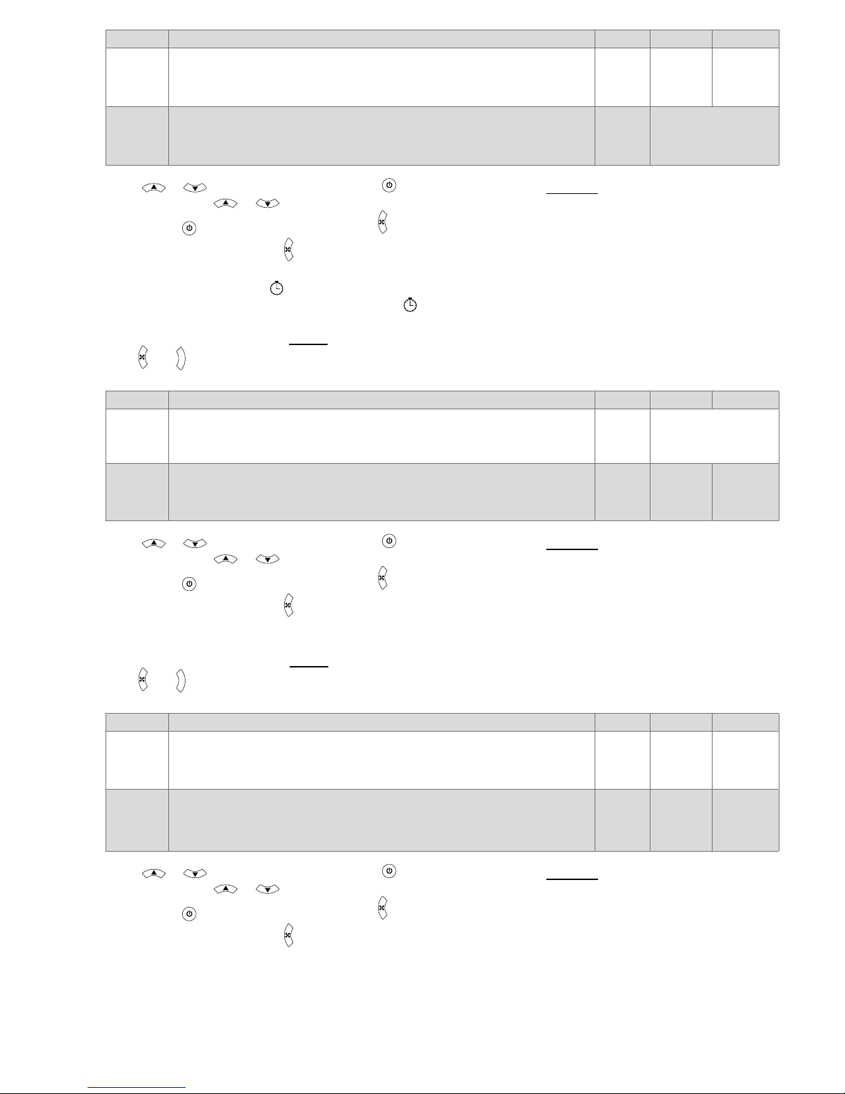
10/126
Parameter Description Default Min Max
MOC
Timer extension
noOC=timer extension off
OC=timer extension on (this excludes the economy and not occupied
holiday modes for the time set with parameter I47)
noOC noOC OC
MOD
Operating mode
nOrM=operation without time zones
tiMb=operation with time zones
HOLY=not occupied holiday mode
nOrM nOrM, tiMb, HOLY
Press or to select a parameter and key to enter data entry mode, display B ashes with the current setting.
Then press button or to change the value.
Press button
to save the settings, or button
ESC
to quit without saving
To exit the menu press button
ESC
again or wait for about 10 seconds.
If timer extension is on, icon
ashes for the time set in parameter I47.
If the timer extension function is not active, the icon
is off.
■ If the quick access mode of the MODE button is set to: Timer extension (I44=1), to access other functions, press but-
tons
ESC
and
M
O
D
E
together to enter the menu for setting the timer extension and season changeover functions.
Parameter Description Default Min Max
MOD
Operating mode
nOrM=operation without time zones
tiMb=operation with time zones
HOLY="not occupied holiday" mode
nOrM nOrM, tiMb, HOLY
SEA
Local season changeover (local season changeover setting for 2 pipe systems:
M01=4 or M01=7)
HEAT=heating mode
CooL=cooling mode
HEAT HEAT CooL
Press or to select a parameter and key to enter data entry mode, display B ashes with the current setting.
Then press button or to change the value.
Press button
to save the settings, or button
ESC
to quit without saving
To exit the menu press button
ESC
again or wait for about 10 seconds.
■ If the quick access mode of the MODE button is set to: Operating mode (I44=2), to access other functions press but-
tons
ESC
and
M
O
D
E
together to enter the menu for setting the timer extension and season changeover functions.
Parameter Description Default Min Max
SEA
Local season changeover (local season changeover setting for 2 pipe systems:
M01=4 or M01=7)
HEAT=heating mode
CooL=cooling mode
HEAT HEAT CooL
MOC
Timer extension
noOC=timer extension off
OC=timer extension on (this excludes the economy and not occupied
holiday modes for the time set with parameter I47)
noOC noOC OC
Press or to select a parameter and key to enter data entry mode, display B ashes with the current setting.
Then press button or to change the value.
Press button
to save the settings, or button
ESC
to quit without saving
To exit the menu press button
ESC
again or wait for about 10 seconds.
11/126
5. Date and time setting (Model TH-xxCSx1)
CLk
yMdH
y-r
2012
M-h
11
day
29
Hr.
11:37
Press and together.
CLK is displayed on display A and yMdH on display B.
Press button
to enter the date and hour setting menu
Parameter Description Min Max
CLk
Date and time setting menu
Y-r
Year
2012 2100
M-h
Month
1 12
day
Day
1 31
Hr.
Time (hour)
0 23
Time (minutes)
0 59
Press button or to select a parameter to be modied and button to enter edit mode, display B ashes with the
current value of the parameter.
Then press button or to change the value.
Press button
to save the settings, or button
ESC
to quit without saving.
To exit the menu press button
ESC
again or wait for about 120 seconds.
Note: setting parameter I46=1 for European zone or I46=2 for USA zone, the device is able to automatically update summertime. If parameter I46=0 (other zones), the summertime update is deactivated.
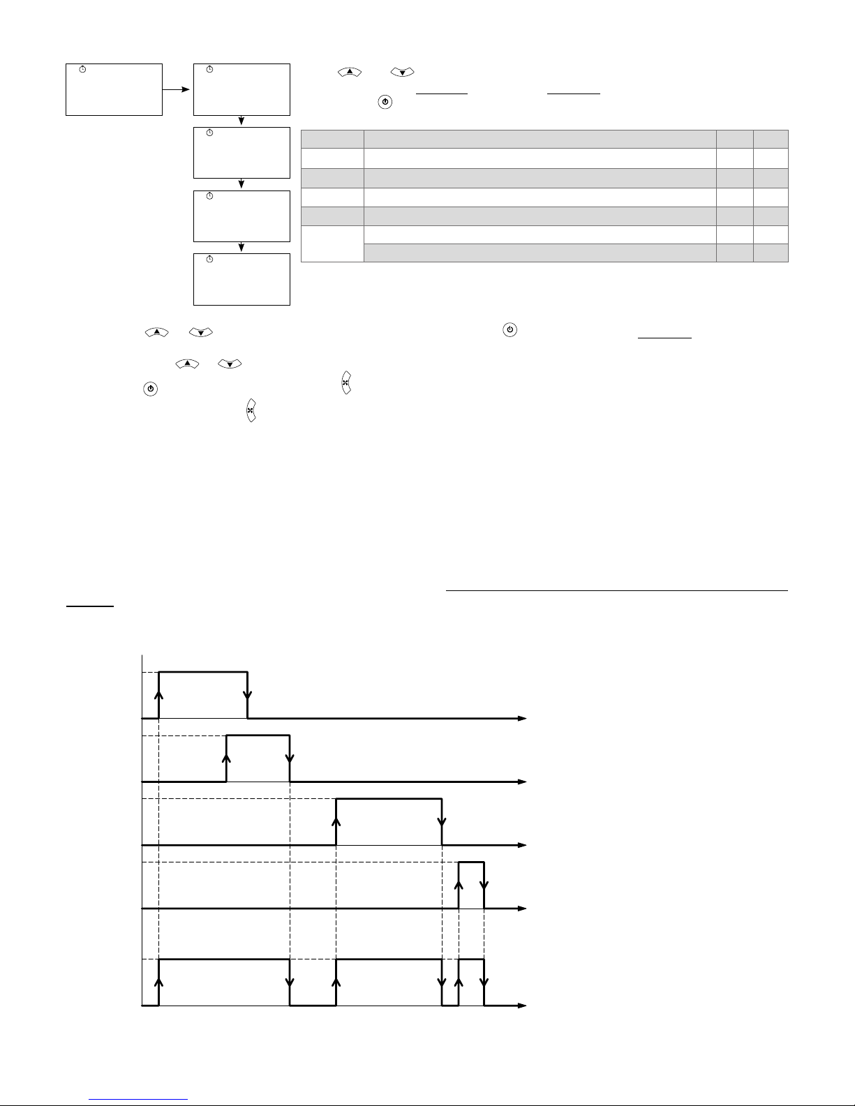
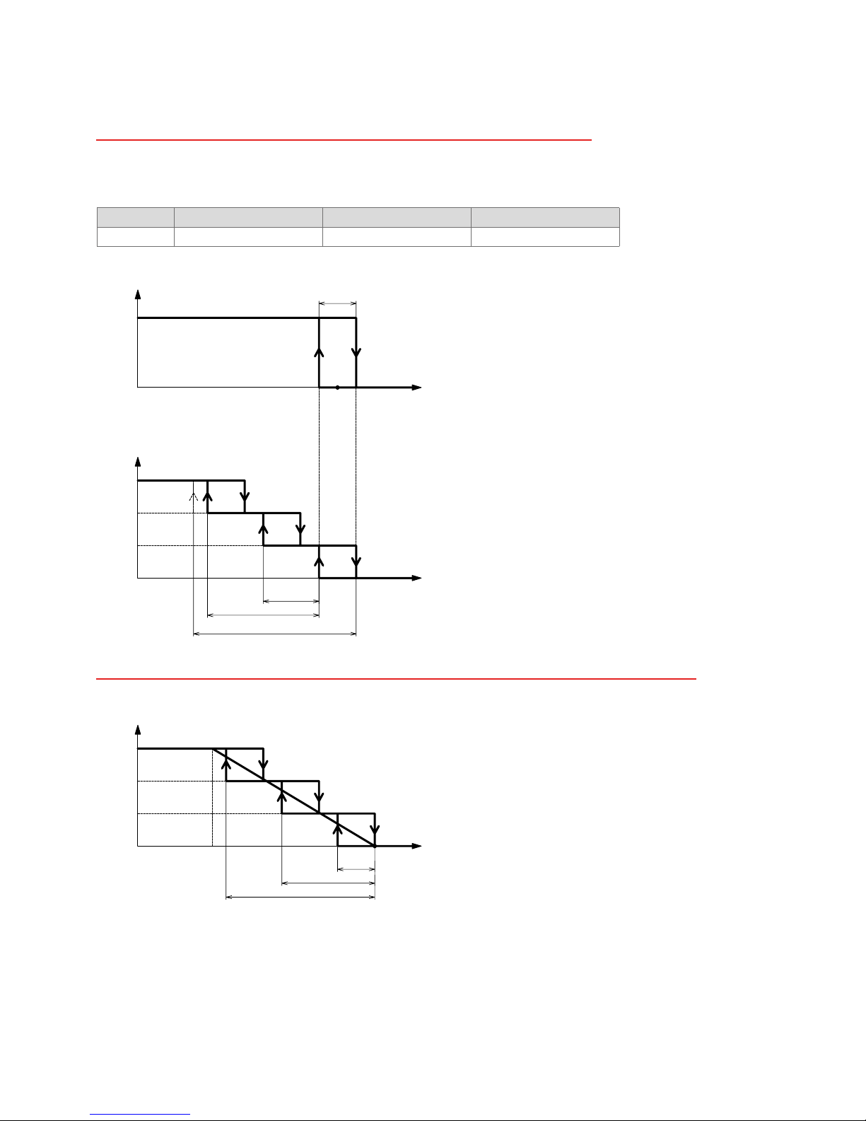
6. TIME ZONES operation and setting (Model TH-xxCSx1)
It is possible to use up to 4 time zones per day. Control is normal within an ON zone.
Outside ON zones, the controller works in economy mode (see “14. Working setpoint, Economy mode and holiday mode”
page 25).
To work with a time zone, set the start time (ON) and the end time (OFF).
If the start time (ON) is equal or previous to the end time (OFF), the corresponding time zone is excluded.
If a time zone is included in another time zone, the rst start time and the last end time will be used by the system.
Time
Time
Time
Time
OFF
ON
OFF
ON
OFF
ON
OFF
ON
Time
OFF
ON
ECO
NO
ECO
NO
ECO
NO
ECO
ECO
ECO
Time
zone 1
Time
zone 2
Time
zone 3
Time
zone 4
Operating
mode
ECO=economy mode, NO ECO=normal mode (control with base setpoint)

12/126
To modify a time zone proceed as follows:
Press buttons and together, the main screen is displayed:
CLK
yMdH
Press button , the following screen is displayed:
WPR
1--7
Press button , the screen with digit 1 ashing (corresponding to zone 1) is displayed;
Tib
1
Press button or to select the zone time to be modied.
Press button
, the screen displays the day of the ashing time zone:
Mon
Press button or to select the day.
Press button
, the screen displays the day, time zone number, and the starting hour (ON) of the ashing zone:
Mon
06:00
1
Then press button or to select the hour.
Press button
, the zone start time stops ashing and is saved to memory, and the minutes of the selected time zone start
ashing.
Press button or to select the minutes.
Press button
, the minutes of the starting time of the time zone stop ashing and are saved to memory.
The screen for setting the end time of the time zone is displayed:
Mon
08:00
1
Then press button or to select the hour.
Press button
, the zone start time stops ashing and is saved to memory, and the minutes of the end of the selected time
zone start ashing
Press button or to select the minutes.
Press button
, the minutes of the ending time of the zone stop ashing and are saved to memory.
The screen for selecting the time zone day is displayed (ashing).
Press button
ESC
to return to the zone selection menu:
Tib
1
Press button
ESC
to return to the main menu or repeat the procedure to set another time zone.
Parameter Description Min Max
WPR
Time zone settings menu
Tib
Zone selection 1 4
x Day of week (x=Mon, Tue, Wed, Thu, Fri, Sat, Sun)
Mon Sun
ON Start of zone (hours) 0 23
Start of zone (minutes) 0 59
OFF End of zone (hours) 0 23
End of zone (minutes) 0 59
13/126
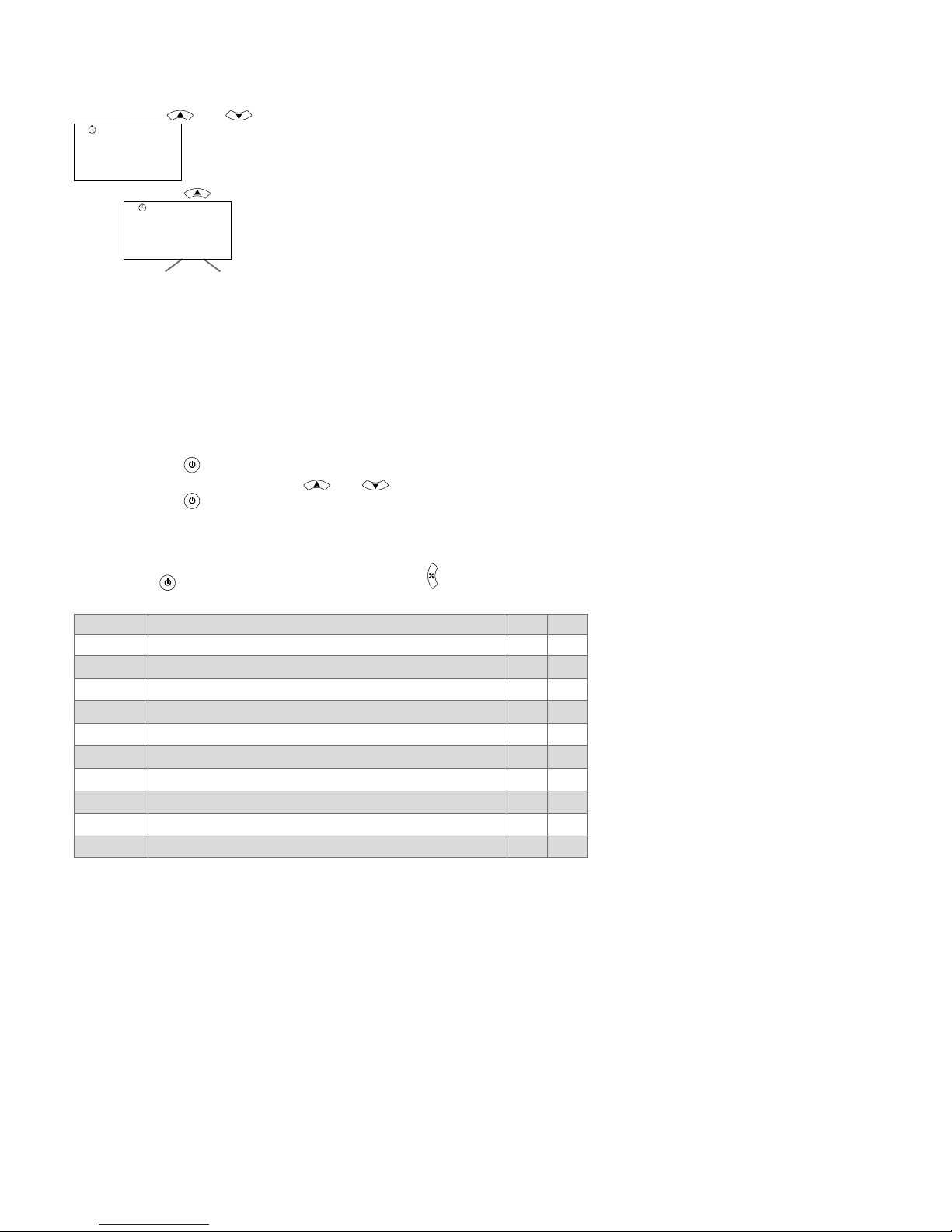
7. TIME ZONE duplication (Model TH-xxCSx1)
It is possible to copy the settings of the time zones of a day on another single day or on 5 days from Monday to Friday or on
2 days from Saturday to Sunday.
To copy the zones from one day to another day follow the procedure described below.
Press buttons and together, the main screen is displayed:
CLK
yMdH
Press the button , the following screen is displayed:
Mo
tu
Ve
tH
fr
Sa
su
MF
SS
Mo
tu
Ve
tH
fr
Sa
su
Day to be copied: destination day
CTb
Mo:Mo
Press the button , the day to be copied ashes:
Select the day to copy with buttons and .
Press the button
, the destination day ashes on which the copy will be done:
If you set “MF“ as the destination, the selected day will be copied to the days from Monday to Friday.
If you set “SS“ as destination, the selected day will be copied to the days from Saturday to Sunday.
Press button
to proceed with duplication, or button
ESC
to cancel.
Parameter Description Min Max
CTb
Copy time zones (Mo, tu, UE, tH, Fr, SA, Su) Mo SS
Mo
Monday
tu
Tuesday
Ve
Wednesday
tH
Thursday
fr
Friday
Sa
Saturday
su
Sunday
MF
copy to Monday, Tuesday, Wednesday, Thursday and Friday
SS
copy to Saturday and Sunday
14/126
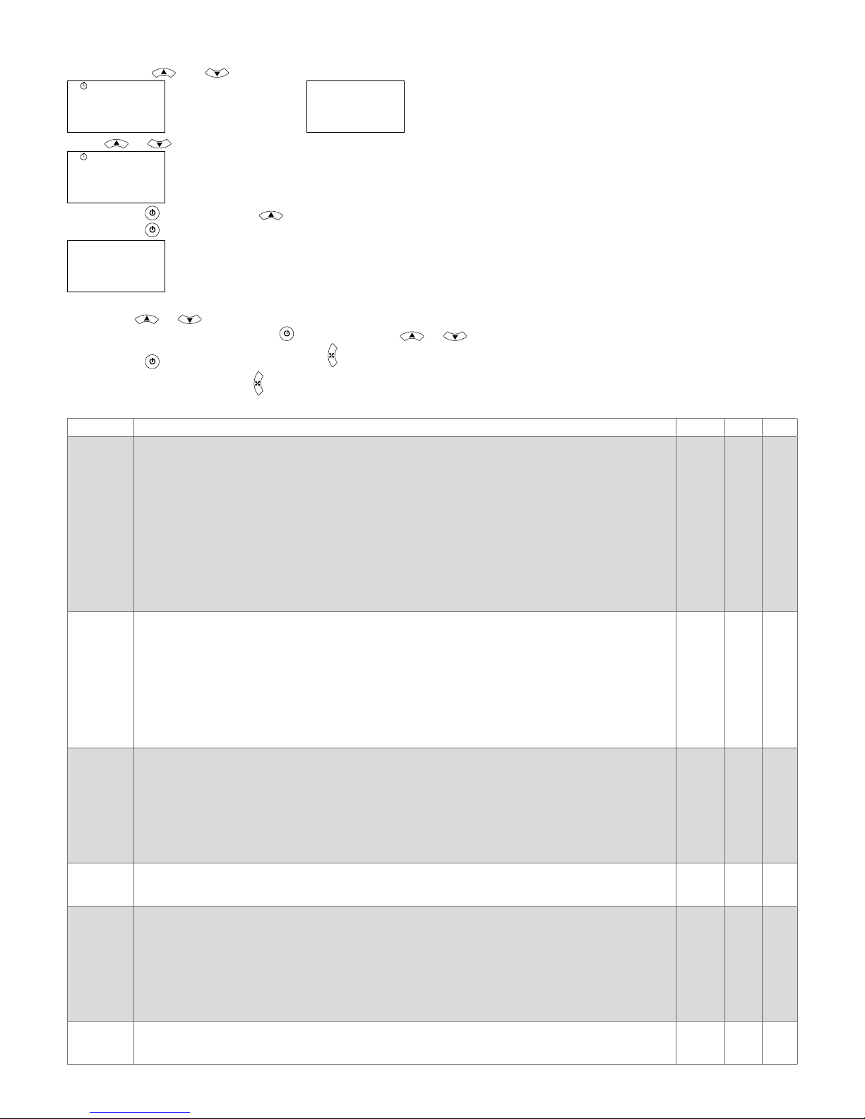
8. Manufacturer parameter setting (level 1 password)
The manufacturer parameters are password protected.
Press buttons and together to access the main menu. The following screen is displayed:
CLK
yMdH
(model TH-xxCSx1) or
AL
noAL
(model TH-xxSSx1)
Press or to display the following screen:
PAS
1
Press button and then button until the value 22 is displayed.
Press button
to access level 1. The screen corresponding to the rst level 1 parameter is displayed:
M01
0
Use button or to scroll through the parameters.
To modify a parameter press button
and then buttons or to select its value.
Press button
to save the value or button
ESC
to quit parameter editing mode without saving.
To quit the menu, press button
ESC
again or wait for about 120 seconds.
Parameter Description Default Min Max
M01
Unit regulation type
0=Heating
1=Heating/heating (2 stage)
2=Heating/cooling with automatic season changeover (2 pipe)
3=Heating/cooling with season changeover via remote contact (2 pipe)
4=Heating/cooling with season changeover via parameter (2 pipe)
5=Heating + electric resistance/cooling, with automatic season changeover (2 pipe + electric resistance)
6=Heating + electric resistance/cooling, with season changeover via remote contact (2 pipe)
7=Heating + electric resistance/cooling, with season changeover via parameter (2 pipe)
8=Heating/Cooling (4 pipe)
9=Heating + electric resistance/cooling (4 pipe + electric resistance)
10=Cooling
11=Cooling/cooling (2 stage)
0 0 11
M02
Electric resistance stage
Determines which heating stages use the electric resistance
0=no stage
1=stage 1
2=stage 2
3=stages 1 and 2
If M01=5, 6 or 7, M02 is automatically forced to 2.
If M01=0, 1, 2, 3 or 4, and M02=0, the fancoil and stage 1 are switched off together without delay.
If the electric resistance is present, and is deactivated, at least the delay set in parameter I35 (see
installer parameters table) must be expired before the fancoil can switch off.
0 0 3
M03
Digital input 1 function:
0=Remote season changeover (INPUT ON=winter, INPUT OFF=summer)
1=Remote On/Off
2=Not occupied holidays (INPUT ON=occupied)
3=Economy (INPUT ON=economy on)
4=Window contact (INPUT OFF=window open)
5=Alarm (INPUT ON=alarm present)
6=Minimum thermostat contact, fancoil water coil
7=Not used
7 0 7
M04
Digital input 1 contact logic:
0=Normally open (open=INPUT OFF, closed=INPUT ON)
1=Normally closed (closed=INPUT OFF, open=INPUT ON)
0 0 1
M05
Digital input 2 function:
0=Remote season changeover (INPUT ON=winter, INPUT OFF=summer)
1=Remote On/Off
2=Not occupied holidays (INPUT ON=occupied)
3=Economy (INPUT ON=economy on)
4=Window contact (INPUT OFF=window open)
5=Alarm (INPUT ON=alarm present)
6=Minimum thermostat contact, fancoil water coil
7=Not used
7 0 7
M06
Digital input 2 contact logic:
0=Normally open (open=INPUT OFF, closed=INPUT ON)
1=Normally closed (closed=INPUT OFF, open=INPUT ON)
0 0 1

15/126
Parameter Description Default Min Max
M07
Analogue input 1 function:
0=Remote regulation sensor
1=Water sensor for automatic season changeover
2=Minimum thermostat sensor (fancoil water coil)
3=Season changeover remote contact (INPUT ON=winter, INPUT OFF=summer)
4=Remote On/Off
5=Not occupied holidays (INPUT ON=occupied)
6=Economy (INPUT ON=economy on)
7=Window contact (INPUT OFF=window open)
8=Alarm (INPUT ON=alarm present)
9=Not used
9 0 9
M08
Analogue input 1 logic (only with M07=3...8):
0=Normally open (open=INPUT OFF, closed=INPUT ON)
1=Normally closed (closed=INPUT OFF, open=INPUT ON)
0 0 1
M09
Analogue input 2 function:
0=Remote regulation sensor
1=Water sensor for automatic season changeover
2=Minimum thermostat sensor (fancoil water coil)
3=Season changeover remote contact (INPUT ON=winter, INPUT OFF=summer)
4=Remote On/Off
5=Not occupied holidays (INPUT ON=occupied)
6=Economy (INPUT ON=economy on)
7=Window contact (INPUT OFF=window open)
8=Alarm (INPUT ON=alarm present)
9=Not used
9 0 9
M10
Analogue input 2 logic (only with M09=3...8):
0=Normally open (open=INPUT OFF, closed=INPUT ON)
1=Normally closed (closed=INPUT OFF, open=INPUT ON)
0 0 1
M11
Analogue input 3 function:
0=Remote regulation sensor
1=Water sensor for automatic season changeover
2=Minimum thermostat sensor (fancoil water coil)
3=Season changeover remote contact (INPUT ON=winter, INPUT OFF=summer)
4=Remote On/Off
5=Not occupied holidays (INPUT ON=occupied)
6=Economy (INPUT ON=economy on)
7=Window contact (INPUT OFF=window open)
8=Alarm (INPUT ON=alarm present)
9=Not used
10=Input 0...10V (Jumper JP1 must be set on 2-3 (0...10V))
9 0 10
M12
Analogue input 3 logic (only with M11=3...8):
0=Normally open (open=INPUT OFF, closed=INPUT ON)
1=Normally closed (closed=INPUT OFF, open=INPUT ON)
0 0 1
M13
Motor type
0=EC motor
1=3 speed on-off motor
0 0 1
M14
EC motor type
0=EC motor with auxiliary relay
1=standard EC motor
0 0 1
M15
Half season function enable
Determines whether to enable the electric resistance for M01=5, 6 and 7 operation on models
TH-0xxSx1, TH-1xxSx1, TH-2xxSx1 (
M13=0), TH-4xxSx1.
0=half season function not enabled
1=half season function enabled In cooling mode, you can use the electric resistance for heating if
the temperature drops below the setpoint (see heating/cooling 2 pipe + electric resistance (M01=5, 6,
7) for the models indicated)
1 0 1
16/126
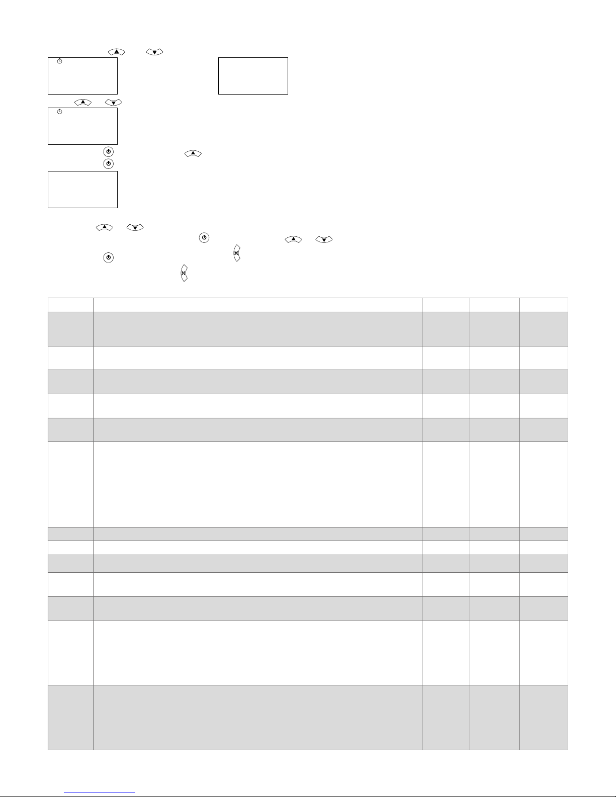
9. Installer parameter setting (level 2 password)
Installer parameters are password protected.
Press buttons and together to access the main menu. The following screen is displayed:
CLK
yMdH
(model TH-xxCSx1) or
AL
noAL
(model TH-xxSSx1)
Press or to display the following screen:
PAS
1
Press button and then button until the value 11 is displayed.
Press button
to access level 1. The screen corresponding to the rst level 1 parameter is displayed:
I01
0
Use button or to scroll through the parameters.
To modify a parameter press button
and then buttons or to select its value.
Press button
to save the value or button
ESC
to quit parameter editing mode without saving.
To quit the menu, press button
ESC
again or wait for about 120 seconds.
Parameter
Description
Default Min Max
I01
Internal temperature correction (K) (°C [°F])
The correction factor is added to the temperature reading of the internal sensor
I01
0 -5.0 [-9.0] 5.0 [9.0]
I02
Measured internal humidity correction (%r.H)
Correction parameter I02 is added to the humidity reading (TH-xxxSH1 models only)
0 -10.0 10.0
I03
External temperature correction AI1 (K) (°C [°F])
Correction factor I03 is added to the external sensor reading AI1
0 -5.0 [-9.0] 5.0 [9.0]
I04
External temperature correction AI2 (K) (°C [°F])
Correction factor I04 is added to the external sensor reading AI2
0 -5.0 [-9.0] 5.0 [9.0]
I05
External temperature correction AI3 (K) (°C [°F])
Correction factor I05 is added to the external sensor reading AI3
0 -5.0 [-9.0] 5.0 [9.0]
I06
Weighting (%) of external sensor AI1 in relation to the internal sensor (if M07=0) to
create the regulation sensor.
I06=0 → only internal sensor used as regulation sensor
I06=100 → only sensor AI1 used as regulation sensor
I06=Y → sensor AI1 and internal sensor used together to create the regulation sensor,
using the following formula Treg=[Ti (100 - Y) + (TA1 x Y)] / 100
The remote sensor AI1 must be set as remote regulation sensor, otherwise the parameter I06 is not considered
0 0 100
I07
Heating setpoint for regulation other than 4 pipe system (°C [°F]) 20.0 [70]
I11 I10
I08
Cooling setpoint for regulation other than 4 pipe system (°C [°F]) 25.0 [77]
I11 I10
I09
Setpoint for 4 pipe regulation (°C [°F]) 21.0 [70]
I11 I10
I10
Maximum regulation setpoint value (°C [°F])
Sets a maximum limit for setpoints I07, I08 and I09
40.0 [104]
I11
40.0 [104]
I11
Minimum regulation setpoint value (°C [°F])
Sets a minimum limit for setpoints I07, I08 and I09
6.0 [43] 6.0 [43]
I10
I12
Economy offset (K) (°C [°F])
In economy mode, the cooling setpoint is increased by I12
In economy mode, the heating setpoint is decreased by I12
Example: I12= 3
BHS=20 - I12= 17°C
BCS=25 + I12= 28°C
3.0 [5] 1.0 [2] 6.0 [11]
I13
"Not occupied holiday" mode offset (K) (°C [°F])
In "not occupied holiday" mode, the cooling setpoint is increased by I13
In "not occupied holiday" mode, the heating setpoint is decreased by I13
Example: I13= 5
BHS=20 - I13= 15°C
BCS=25 + I13= 30°C
5.0 [9] 1.0 [2] 10.0 [18]

17/126
Parameter
Description
Default Min Max
I14
Frost protection setpoint (°C [°F]) 5.0 [41] 4.0 [39] 10.0 [50]
I15
Heating setpoint for automatic season changeover sensor (water sensor) (°C [°F]).
Used only for the following congurations: M01=2, 5
28.0 [82] 26.0 [79] 40.0 [104]
I16
Cooling setpoint for automatic season changeover sensor (water sensor) (°C [°F]).
Used only for the following congurations: M01=2, 5
17.0 [63] 10.0 [50] 25.0 [77]
I17
Minimum thermostat setpoint (°C) (constant hysteresis=2°C)
Can be used with M07=2, M09=2, M11=2 and when M03≠6 and M05≠6
(see “20. Minimum thermostat” page 30)
21.0 [70] 19.0 [66] 50.0 [122]
I18
Heating hysteresis for on/off output (K) (°C [°F]) 1.0 [1.8] 0.5 [1.0] 2.0 [3.6]
I19
Cooling hysteresis for on/off output (K) (°C [°F]) 1.0 [1.8] 0.5 [1.0] 2.0 [3.6]
I20
Differential between 2 stages (K) (°C [°F]) 2.0 [3.6] 0 [0] 3.0 [5.4]
I21
Neutral zone for 4 pipe systems (K) (°C [°F]) 0.5 [1.0] 0.5 [1.0] 5.0 [9.0]
I22
Heating proportional band (K) (°C [°F]) 2.0 [3.6] 1.0 [1.8] 5.0 [9.0]
I23
Cooling proportional band (K) (°C [°F]) 2.0 [3.6] 1.0 [1.8] 5.0 [9.0]
I24
Integral time (s). Parameter used to regulate the 0..10V modulating valves
If I24=0, integral action is excluded.
0 0 999
I25
Speed 1 activation point for 3 speed motor (%) (see ventilation function) 10 1 15
I26
Speed 2 activation point for 3 speed motor (%) (see ventilation function) 65 30 75
I27
Speed 3 activation point for 3 speed motor (%) (see ventilation function) 100 80 100
I28
Speed maintained when setpoint reached.
Maintains speed 1 without regulation depending on season.
0=fancoil stopped when setpoint reached
1=fancoil at speed 1 when setpoint reached in heating/cooling modes
2=fancoil at speed 1 when setpoint reached in cooling mode only
3=fancoil at speed 1 when setpoint reached in heating mode only
4=fancoil at manual speed selected when setpoint reached in heating/cooling modes
5=fancoil at manual speed selected when setpoint reached in cooling mode only
6=fancoil at manual speed selected when setpoint reached in heating mode only
0 0 6
I29
Minimum EC motor starting voltage (see ventilation function) 1.0 0
I30
I30
Maximum voltage applicable to EC motor (see ventilation function) 8.0
I29
10.0
I31
Starting point of EC motor in regulation (% valve regulation).
Enables the EC motor to be started only if the minimum opening percentage set in
I31 has been reached by the valve (see ventilation function)
10 0 100
I32
Speed 1 of EC motor (% of range I30 - I29)
0%=I29 setting
100%=I30 setting (see ventilation function)
10 0 15
I33
Speed 2 of EC motor (% of range I30 - I29)
0%=I29 setting
100%=I30 setting (see ventilation function)
65 30 75
I34
Speed 3 of EC motor (% of range I30 - I29)
0%=I29 setting
100%=I30 setting (see ventilation function)
100 80 100
I35
Delay on ventilation deactivation (s) (only considered if electric resistance is active)
Determines the minimum fan run time following deactivation of the electric resistance
to prevent the resistance itself overheating.
30 0 600
I36
Fan start delay after valve opening (s)
Prevent irritating ventilation (too cold in the winter or hot in the summer) and allows the
coil to heat or cool enough before starting the fan.
0 10 600
I37
Fan boost
Denes the fan start during regulation
0=Fan starts at set speed
1=Fan starts at maximum speed for 1 s and then goes to set speed
1 0 1
I38
Air destratication function
Determines whether to start the fan at minimum speed if regulation is not active to
prevent stratifying the air when the regulation sensor is mounted on the fancoil return.
0=OFF
1=ON in heating and cooling
2=ON in heating only
3=ON in cooling only
1 0 3
I39
Fan start time during destratication cycle (minutes) 1 1 5

18/126
Parameter
Description
Default Min Max
I40
Fan stop time if regulation is not active before starting a new destratication cycle
(minutes)
10 1 60
I41
Maximum fan run time before lter is considered dirty (hours)
0=Not used
X=Maximum number of hours of fan operation before a warning is displayed.
2000 0 9990
I42
Value displayed on display A
0= Internal sensor temperature
1= external sensor temperature AI1
2= external sensor temperature AI2
3= external sensor temperature AI3
4= operating temperature (see “11. Regulation sensor(s)” page 24)
5= humidity reading (only models TH-xxxSH1)
6= operating setpoint (see “14. Working setpoint, Economy mode and holiday mode”
page 25)
7= value of 0..10V output AO1 (V)
8= value of 0..10V output AO2 (V)
9= value of 0..10V output AO3 (V)
0 0 9
I43
Value displayed on display B
0= Internal sensor temperature
1= external sensor temperature AI1
2= external sensor temperature AI2
3= external sensor temperature AI3
4= operating temperature (see “11. Regulation sensor(s)” page 24)
5= humidity reading (only models TH-xxxSH1)
6= operating setpoint (see “14. Working setpoint, Economy mode and holiday mode”
page 25)
7= value of 0..10V output AO1 (V)
8= value of 0..10V output AO2 (V)
9= value of 0..10V output AO3 (V)
10= current hours:minutes
11= total hours of fancoil operation
12= measure of input AI3 set as 0...10V input
13= display B switched off
10 0 13
I44
Mode key function
0= local season changeover with M01=4, M01=7
1= timer extension.
2= operating mode (normal, time zones, or “not occupied holiday”)
1 0 2
I45
Unit of measurement (0=°C, 1=°F) 0 0 1
I46
Summertime changeover
Determines whether summertime is used automatically
0=no
1=yes (European summertime)
2=yes (USA summertime)
1 0 2
I47
Duration of extension timer (minutes)
In timer extension mode, the working setpoint does not consider economy and
holiday mode for the time I47
60 1 480
I48
Baudrate:
Modbus 1=2400, 2=4800, 3=9600, 4=19200, 5=38400 bit/s only TH-xMxSx1
BACnet 3=9600, 4=19200, 5=38400, 6=76800 bit/s only TH-xBxSx1
4
4
1
3
5
6
I49
Modbus parity (0=none, 1= odd, 2=even)
(only models TH-xMxSx1)
2 0 2
I50
Device's Modbus address (1…247)
(only models TH-xMxSx1)
1 1 247
I51
Reset fancoil hour counter
Hours of fancoil operation are memorised.
When it exceeds I41, the icon
is displayed. To reset the counter, enter I51=1.
The parameter returns to 0 automatically after resetting.
0 0 1
I52
Comfort function
0= current setpoint adjustable in quick access parameter setting
1= offset of setpoint adjustable in quick access parameter setting
For further details see paragraph “Setpoint setting” page 8
0 0 1
I53
Relay for pump (only for model TH-4xxSx1 set as 2-pipe system (M01=2, 3, 4))
0= relay for pump always deactivated
1= relay for pump activated together with regulation valve
0 0 1

19/126
Parameter
Description
Default Min Max
I54
Working season selection in 2-pipe system (M01=2, 5) with temperature of water sensor between I15 and I16 (see paragraph “12. Automatic season changeover with
water sensor (M01=2 or 5)” page 24)
0= heating (on startup)
1= cooling (on startup)
2= season not dened, regulation stopped
0 0 2
I55
Low limit of scale for input 0...10V 0 -50
I56
I56
High limit of scale for input 0...10V 2000
I55
9999
I57
Unit of measure on display B for input 0...10V
0= ppm
1= %r.h.
2= without unit
0 0 2
I58
Correction for input 0...10V AI3 0 -98.0 98.0
I59
Fan activation
It allows exclusion of the fan
0= fan not used
1= fan used
1 0 1
I60
BACnet mac address 3 0 254
I61
BACnet max masters 127 0 127
I62
BACnet low device ID
BACnet device ID = (I63 x 10000) + I62
7000 0 9999
I63
BACnet high device ID
BACnet device ID = (I63 x 10000) + I62
22 0 419

20/126
10. Digital and analogue input logic
• Digital inputs
1. Digital input 1 (DI1):
Parameter
M03=0
Remote season changeover
contact
M04 =
0 1
Summer
Winter
M03=1
Remote On/Off
M04 =
0 1
On
Off
M03=2
Not occupied
M04 =
0 1
"Not occupied holiday" mode
Occupied mode
M03=3
Economy mode
M04 =
0 1
No economy
Economy
M03=4
Window contact
M04 =
0 1
Window open
Window closed
M03=5
Alarm
M04 =
0 1
No alarm
Alarm active
M03=6
Minimum thermostat
M04 =
0 1
Open
Closed
2. Digital input 2 (DI2):
Parameter
M05=0
Remote season changeover
contact
M06 =
0 1
Summer
Winter
M05=1
Remote On/Off
M06 =
0 1
On
Off
M05=2
Not occupied
M06 =
0 1
"Not occupied holiday" mode
Occupied mode
M05=3
Economy mode
M06 =
0 1
No economy
Economy
M05=4
Window contact
M06 =
0 1
Window open
Window closed
M05=5
Alarm
M06 =
0 1
No alarm
Alarm active
M05=6
Minimum thermostat
M06 =
0 1
Open
Closed
21/126
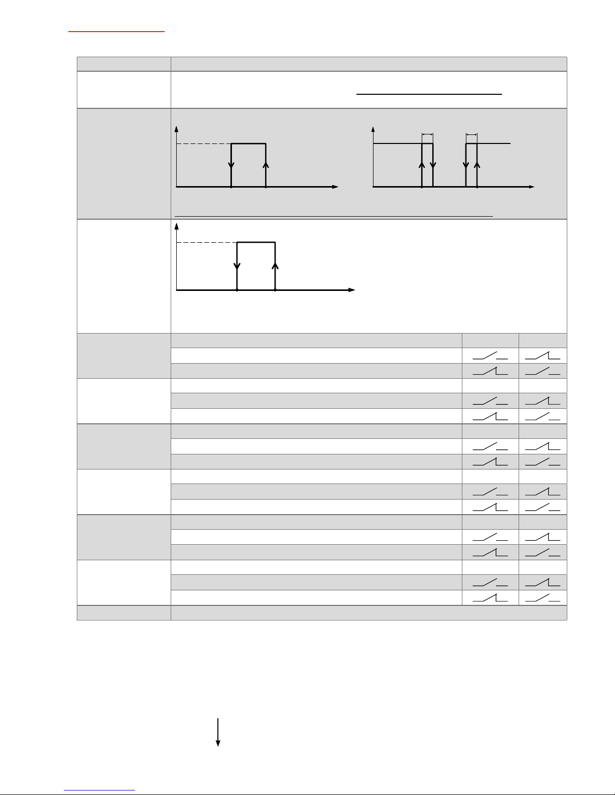
• Analogue inputs
1. Analogue input 1 (AI1)
Parameter
M07=0
Remote regulation
sensor
Sensor AI1 is used in combination with the internal sensor to obtain the nal regulation temperature in relation to the value of I06 (see “11. Regulation sensor(s)” page 24)
M07=1
Water sensor for
season changeover
I54=0 or 1 I54=2
Summer
Winter
Temp. water
I16
I15
Summer
Winter
Temp. water
I16
I15
0,5°C
[1,0°F]
0,5°C
[1,0°F]
On startup, if the water temperature sensor reading is between I16 and I15, see paragraph
“12. Automatic season changeover with water sensor (M01=2 or 5)” page 24
M07=2
Minimum thermostat
sensor
Minimum
thermostat
open
Minimum
thermostat
closed
I17 -
2°C
I17
Temp.
water coil
On startup, if the temperature of the heating coil is between I17 and I17 - 2, the minimum
thermostat is deemed to be open
M07=3
Remote season
changeover contact
M08 =
0 1
Summer
Winter
M07=4
Remote On/Off
M08 =
0 1
On
Off
M07=5
Not occupied holi-
day
M08 =
0 1
"Not occupied holiday" mode
Occupied mode
M07=6
Economy mode
M08 =
0 1
No economy
Economy
M07=7
Window contact
M08 =
0 1
Window open
Window closed
M07=8
Alarm
M08 =
0 1
No alarm
Alarm active
M07=9
Sensor not used
For congurations M07 from 3 to 8, analogue input 1 is used as digital input. The contact is considered closed if it is shortcir-
cuited at the analogue input. The contact is considered open if there is no connection.
Note:
If one or more digital and/or analogue inputs are congured with the same control functionality, then the input with the higher
priority is considered.
Input priority:
Digital input 1 (DI1) - Highest priority
Digital input 2 (DI2)
Analogue input 1 (AI1)
Analogue input 2 (AI2)
Analogue input 3 (AI3) - Lowest priority
22/126
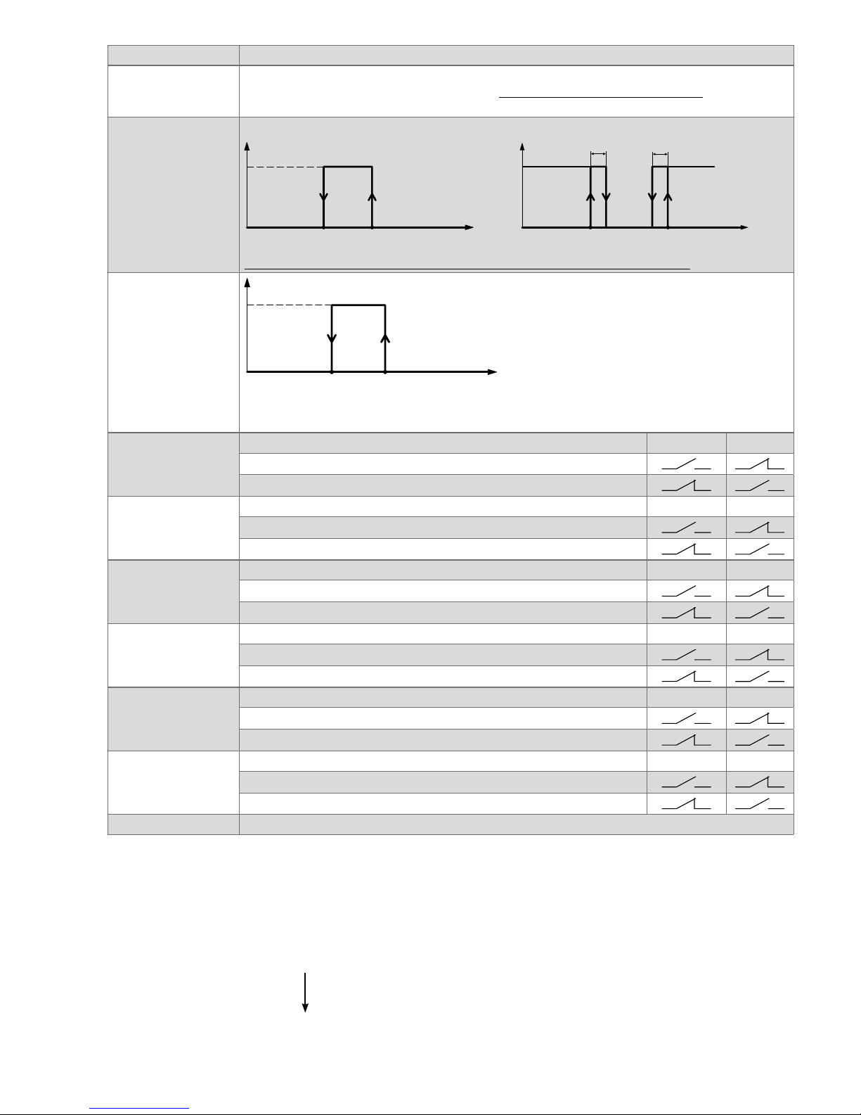
2. Analogue input 2 (AI2)
Parameter
M09=0
Remote internal
sensor
Sensor AI2 is used in combination with the internal sensor to obtain the nal regulation temperature in relation to the value of I06 (see “11. Regulation sensor(s)” page 24).
M09=1
Water sensor for
season changeover
I54=0 or 1 I54=2
Summer
Winter
Temp. water
I16
I15
Summer
Winter
Temp. water
I16
I15
0,5°C
[1,0°F]
0,5°C
[1,0°F]
On startup, if the water temperature sensor reading is between I16 and I15, see paragraph
“12. Automatic season changeover with water sensor (M01=2 or 5)” page 24
M09=2
Minimum thermostat
sensor
Minimum
thermostat
open
Minimum
thermostat
closed
I17 -
2°C
I17
Temp.
water coil
On startup, if the temperature of the heating coil is between I17 and I17 - 2, the minimum
thermostat is deemed to be open
M09=3
Remote season
changeover contact
M10 =
0 1
Summer
Winter
M09=4
Remote On/Off
M10 =
0 1
On
Off
M09=5
Not occupied holi-
day
M10 =
0 1
“Not occupied holiday” mode
Occupied mode
M09=6
Economy mode
M10 =
0 1
No economy mode
Economy mode
M09=7
Window contact
M10 =
0 1
Window open
Window closed
M09=8
Alarm
M10 =
0 1
No alarm
Alarm active
M09=9
Sensor not used
For congurations M09 from 3 to 8, analogue input 1 is used as a digital input. The contact is considered closed if it is shortcir-
cuited at the analogue input. The contact is considered open if there is no connection.
Note:
If one or more digital and/or analogue inputs are congured with the same control functionality, then the input with the higher
priority is considered.
Input priority:
Digital input 1 (DI1) - Highest priority
Digital input 2 (DI2)
Analogue input 1 (AI1)
Analogue input 2 (AI2)
Analogue input 3 (AI3) - Lowest priority
23/126
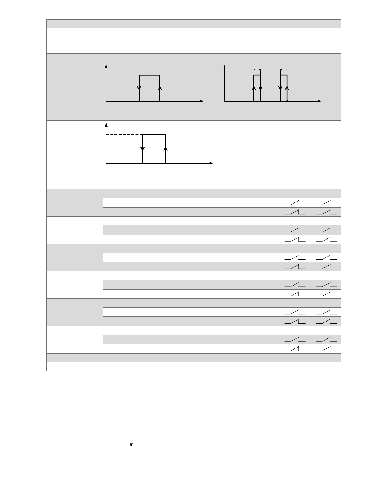
3. Analogue input 3 (AI3):
Parameter
M11=0
Remote internal
sensor
Sensor AI3 is used in combination with the internal sensor to obtain the nal regulation temperature in relation to the value of I06 (see “11. Regulation sensor(s)” page 24)
.
M11=1
Water sensor for
season changeover
I54=0 or 1 I54=2
Summer
Winter
Temp. water
I16
I15
Summer
Winter
Temp. water
I16
I15
0,5°C
[1,0°F]
0,5°C
[1,0°F]
On startup, if the water temperature sensor reading is between I16 and I15, see paragraph
“12. Automatic season changeover with water sensor (M01=2 or 5)” page 24
M11=2
Minimum thermostat
sensor
Minimum
thermostat
open
Minimum
thermostat
closed
I17 -
2°C
I17
Temp.
water coil
On startup, if the temperature of the heating coil is between I17 and I17 - 2, the minimum
thermostat is deemed to be open
M11=3
Remote season
changeover contact
M12 =
0 1
Summer
Winter
M11=4
Remote On/Off
M12 =
0 1
On
Off
M11=5
Not occupied holi-
day
M12 =
0 1
"Not occupied holiday" mode
Occupied mode
M11=6
Economy mode
M12 =
0 1
No economy
Economy
M11=7
Window contact
M12 =
0 1
Window open
Window closed
M11=8
Alarm
M12 =
0 1
No alarm
Alarm active
M11=9
Sensor not used
M11=10
Input 0...10V
For congurations M11 from 3 to 8, analogue input 1 is used as a digital input. The contact is considered closed if it is shortcir-
cuited at the analogue input. The contact is considered open if there is no connection.
Note:
If one or more digital and/or analogue inputs are congured with the same control functionality, then the input with the higher
priority is considered.
Input priority:
Digital input 1 (DI1) - Highest priority
Digital input 2 (DI2)
Analogue input 1 (AI1)
Analogue input 2 (AI2)
Analogue input 3 (AI3) - Lowest priority
24/126
11. Regulation sensor(s)
The sensor used for control can be:
- the internal controller sensor
- an external sensor selected between AI1,AI2,AI3.
- the internal controller sensor combined to any of the remote sensor AI1,AI2,AI3 with a certain weight This permits to obtain
an optimized control in rooms where temperature may be different from one side to another
To use the internal sensor as a control sensor, set parameter I06 to 0.
To use external sensor AI1 as a control sensor, set parameter M07=0 and I06=100.
To use the internal sensor together with sensor AI1 with a 25% weighting of remote sensor AI1, set parameters M07=0 and
I06=25.
The operating temperature becomes Treg=[Ti (100 - I06) + (TAI1 x I06)] / 100
with Ti=internal sensor temperature, TAI1=remote sensor temperature AI1.
In the case one or more sensors are congured as external working sensors (M07=0 and/or M09=0 and/or M11=0), only one
sensor is considered to be combined with the internal sensor: the sensor with highest priority.
The sensor AI1 has priority over sensor AI2, and sensor AI2 has priority over sensor AI3.
Note: if no external sensor is used as a remote sensor (M07≠0, M09≠0, M11≠0), the internal sensor is used as the control sensor even if I06 is different from 0.
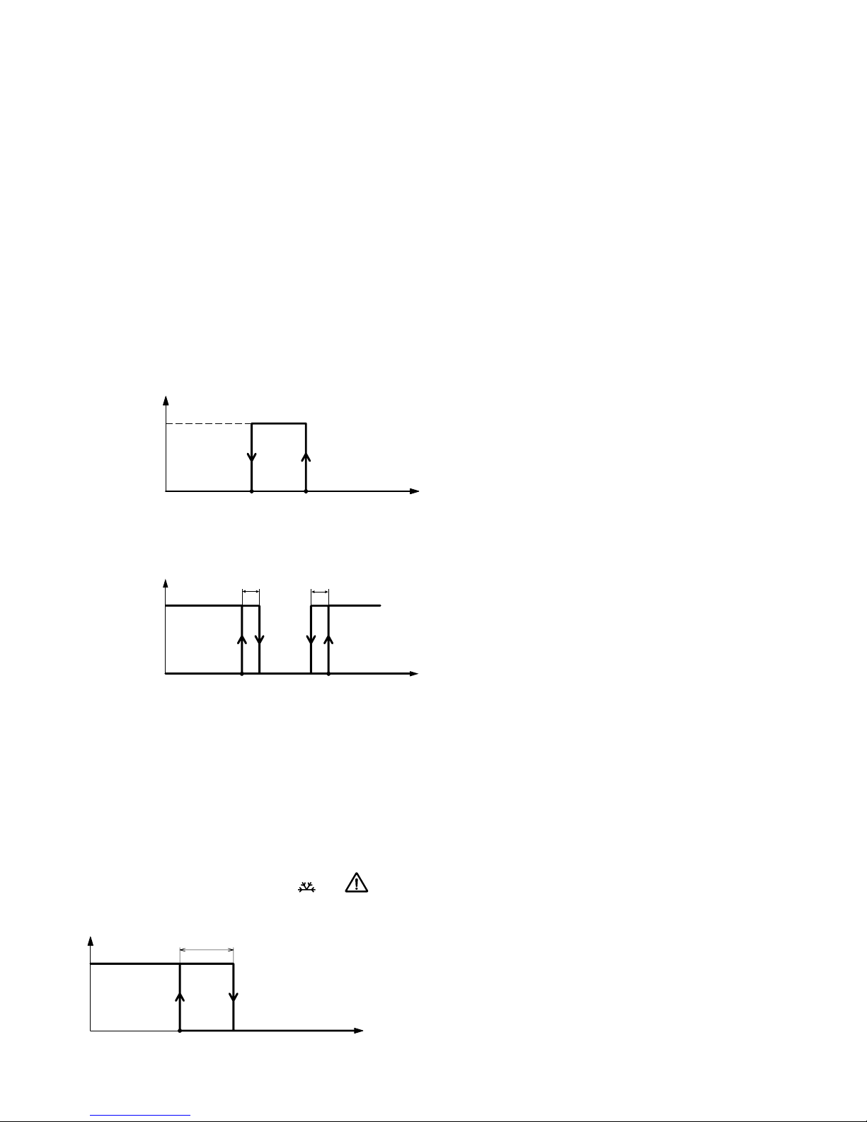
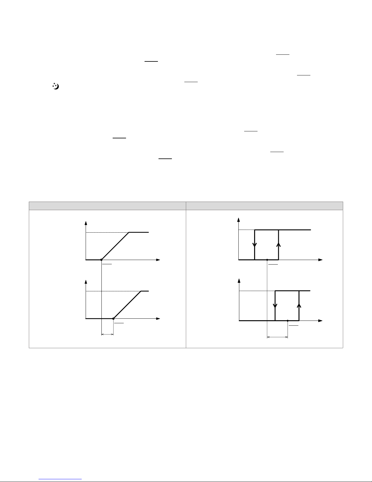
12. Automatic season changeover with water sensor (M01=2 or 5)
The selection of working season si done automatically (for operating modes M01=2 or 5) by external sensor set as water sen-
sor (M07=1 or M09=1 or M11=1). According to parameter’s value I54, season changeover is done on the following way:
I54=0 o 1
Summer
Winter
Temp. water
I16
I15
On startup, if temperature of water sensor is between I16 and I15 the working season is heating (if I54=0) or cooling (if
I54=1). If temperature of water sensor then increases and reaches I15, the working season becomes heating. If temperature
of water sensor then decreases and reaches I16, the working season becomes cooling.
I54=2
Summer
Winter
Temp. water
I16
I15
0,5°C
[1,0°F]
0,5°C
[1,0°F]
On startup, if temperature of water sensor is between I16 and I15 the working season is not dene and no regulation takes
place. If temperature of water sensor then increases and reaches I15, the working season becomes heating. If temperature
of water sensor then decreases and reaches I15 - 0.5°C [1.0°F], the working season is not dened and regulation is stopped.
If temperature of water sensor then decreases and reaches I16, the working season becomes cooling. If temperature increases and reaches I16 + 0.5°C [1.0°F], the working season is not dened and regulation is stopped.
13. Frost protection
If operating temperature falls below I14 (frost setpoint), heating outputs are activated and the fan starts at maximum speed (if
heating outputs are present) and icons and ash.
If operating temperature rises above I14 + 2°C, the frost protection is deactivated.
Note: frost protection is active even if device is OFF
ON
OFF
Temp.
2°C
Anti Frost
AFS
(I14)
25/126
14. Working setpoint, ECONOMY mode and HOLIDAY mode
If a digital contact is congured as remote contact “not occupied holiday” M03=2 or M05=2 or a remote sensor is congured
as remote contact “not occupied holiday” M07=5 or M09=5 or M11=5, “not occupied holiday“ mode can be activated if the
corresponding contact is in the appropriate position (see digital and analogue input logic ).
Installations different from 4 pipe system (M01≠8 and 9):
In “not occupied holiday” mode, the heating setpoint is decreased by I13 (see chart 2 pipe heating, WHS), the cooling setpoint
is increased by I13 (see chart 2 pipe cooling, WCS).
Installations with 4 pipe system (M01=8 and 9):
In “not occupied holiday” mode, the heating activation point is decreased by I13 (see chart 4 pipe heating, WHS), the cooling
activation point is increased by I13 (see chart 4 pipe cooling, WCS).
The icon
is activated to indicate that “not occupied holiday” mode is active.
If one of the digital contacts is congured as remote contact “energy saving” M03=3 or M05=3 or a sensor is congured as
remote contact “energy saving” M07=6 or M09=6 or M11=6, energy saving mode can be activated if the corresponding contact
is in the appropriate position (see digital and analogue inputs logic).
Installations different from 4 pipe system (M01≠8 and 9):
In economy mode, the heating setpoint is decreased by I12 (see chart 2 pipe heating, WHS), the cooling setpoint is increased
by I12 (see chart 2 pipe cooling, WCS).
Installations with 4 pipe system (M01=8 and 9):
In economy mode, the heating activation point is decreased by I12 (see chart 4 pipe heating, WHS), the cooling activation
point is increased by I12 (see chart 4 pipe cooling, WCS).
The “ECO“ icon is activated to indicate “energy saving” mode.
The “not occupied holiday” mode has priority over economy mode when both modes are activated.
Chart 2 pipe (analog output, cooling) Chart 2 pipe (digital output, cooling)
100
0
Temp.
Outputs
BCS
(I08)
100
0
Temp.
Outputs
(I12 o I13)
WCS
WCS
ECONOMY
or
HOLIDA
Y
100
0
Temp.
Outputs
BHS
(I07)
100
0
Temp.
Outputs
WHS
WHS
ECONOMY
or
HOLIDAY
(I12 o I13)
100
0
Temp.
Outputs
BCS
(I08)
100
0
Temp.
Outputs
ON
OFF
Temp
Outputs
BCS
(
I08
)
ON
OFF
Temp
Outputs
(I12 o I13)
(I12 o I13)
WCS
WCS
WCS
WCS
ECONOMY
or
HOLIDAY
ECONOMY
or
HOLIDA
Y
100
0
Temp.
Outputs
BHS
(I07)
100
0
Temp.
Outputs
ON
OFF
Temp
Outputs
BHS
(
I07
)
ON
OFF
Temp
Outputs
(I12 o I13)
WHS
WHS
WHS
WHS
ECONOMY
or
HOLIDAY
ECONOMY
or
HOLIDAY
(I12 o I13)
26/126
Chart 2 pipe (analog output, heating) Chart 2 pipe (digital output, heating)
100
0
Temp.
Outputs
BHS
(I07)
100
0
Temp.
Outputs
WHS
WHS
ECONOMY
or
HOLIDAY
(I12 o I13)
100
0
Temp.
Outputs
BHS
(I07)
100
0
Temp.
Outputs
ON
OFF
Te
mp
Outputs
BHS
(
I07
)
ON
OFF
Te
mp
Outputs
(I12 o I13)
WHS
WHS
WHS
WHS
ECONOMY
or
HOLIDAY
ECONOMY
or
HOLIDAY
(I12 o I13)
Chart 4 pipe (analog output) Chart 4 pipe (digital output)
100
0
Temp
.
Outputs
BS4P
(I09)
100
0
Temp
.
Outputs
BS4P
(I09)
(I12 o I13)(I12 o I13)
WCSWHS
WCSWHS
ECONOMY
or
HOLIDA
Y
100
0
Temp.
Outputs
BS4P
(I09)
100
0
Temp.
Outputs
BS4P
(I09)
ON
OFF
Temp
Outputs
BS4P
(
I09
)
ON
OFF
Te
mp
Outputs
BS4P
(I09)
(I12 o I13)(I12 o I13)
(I12 o I13)(I12 o I13)
WCSWHS
WCSWHS
WCSWHS
WCSWHS
ECONOMY
or
HOLIDAY
ECONOMY
or
HOLIDA
Y
It is possible to visualize the working setpoint by setting parameter I42 or I43 to 6. On this case the value of WHS is visualized
in heating mode, the value of WCS is visualized in cooling mode and if working season is not dened (I54=2, and temperature
of water sensor between I15 and I16), the message “---“ is visualized.
If no contacts or sensors are congured in “not occupied holiday” or "energy saving" mode, and if the operating mode has
been set manually with time zones (see “4. Quick access parameter setting” page 8), then within the time zone regulation
is controlled with the basic setpoint; in this case “display C” (see “3. Display, keyboard and icons” page 7) indicates the
number of the active zone. Outside the time zone, economy mode is active.
Otherwise, the contact or sensor status congured in “not occupied holiday” or “energy saving” mode has higher priority, and
time zones are not considered (TH-xxCSx1 models)
If no contacts or sensors are congured as “not occupied holiday” or “energy saving” and if operating mode is in holiday mode
(manually set using quick access parameters → see “MODE button functionality” page 9), holiday mode is active. Other-
wise the contact or sensor status congured in the “not occupied holiday” or “energy saving” mode has priority over manual
setting.
When timer extension mode is activated manually, it takes priority over energy saving, holiday (see “15. Timer extension
mode” page 27) and time zone modes (TH-xxCSx1 models).
27/126
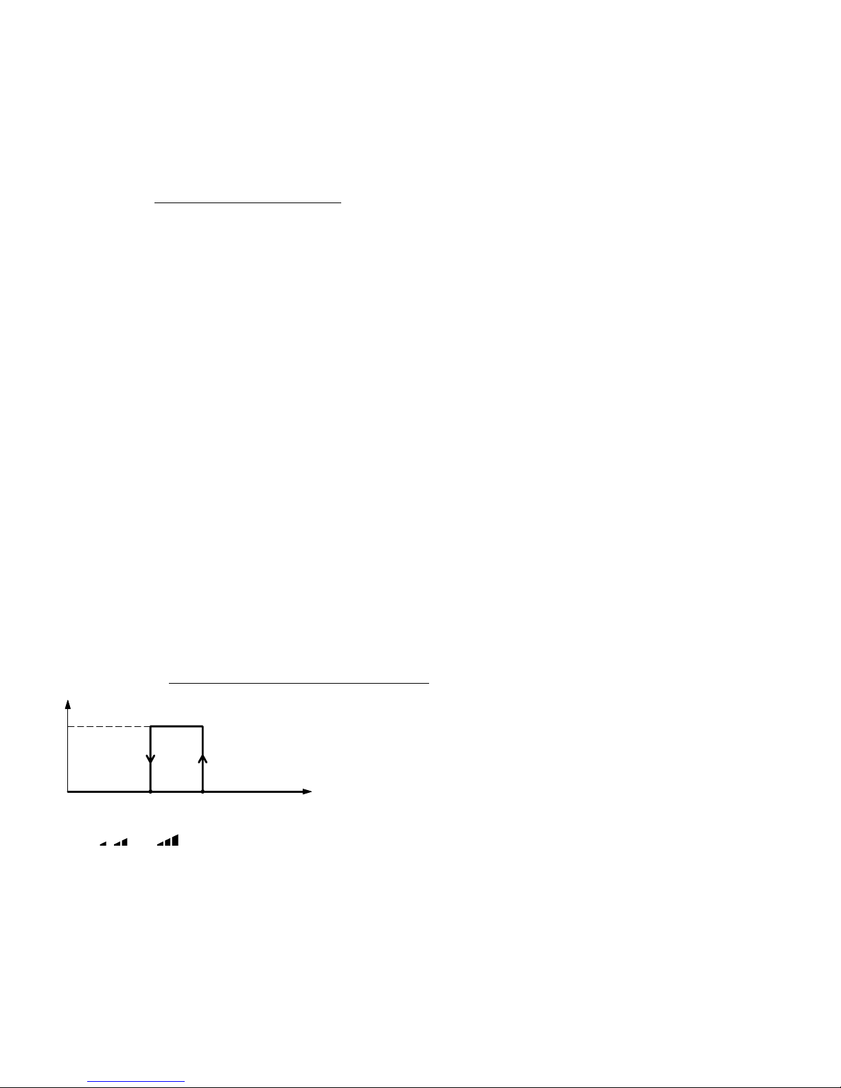
15. Timer extension mode
If the “energy saving”, ”not occupied holiday” and time zone modes are active, the operating setpoints are calculated in relation
to parameters I12 (economy offset) and I13 (“not occupied holiday” offset).
It is possible to bypass these functions for a certain time (parameter I47) and to maintain control with the base setpoints, by
activating timer extension mode.
Timer extension mode can be activated manually by setting parameter MOC to OC (see “MODE button functionality” page 9).
Once activated, a delay equal to the value of I47 must expire before normal operation resumes.
16. Fancoil with EC motor (models TH-0xxSx1, TH-1xxSx1, TH-2xxSx1)
Parameter M13=0.
Device is able to control 2 EC motors with parameter M14.
If M14=0, 2 outputs are used to control the EC motor: one relay output and one 0...10V analogue output.
When the motor starts, the relay output is activated rst, while the analogue output remains at 0V.
After 1 second, the analogue output is also activated.
When the motor is stopped, the analogue output returns to 0V.
After 1 second, the relay is deenergized.
If M14=1, only the analogue 0…10V output is activated to control the EC motor, without the auxiliary relay.
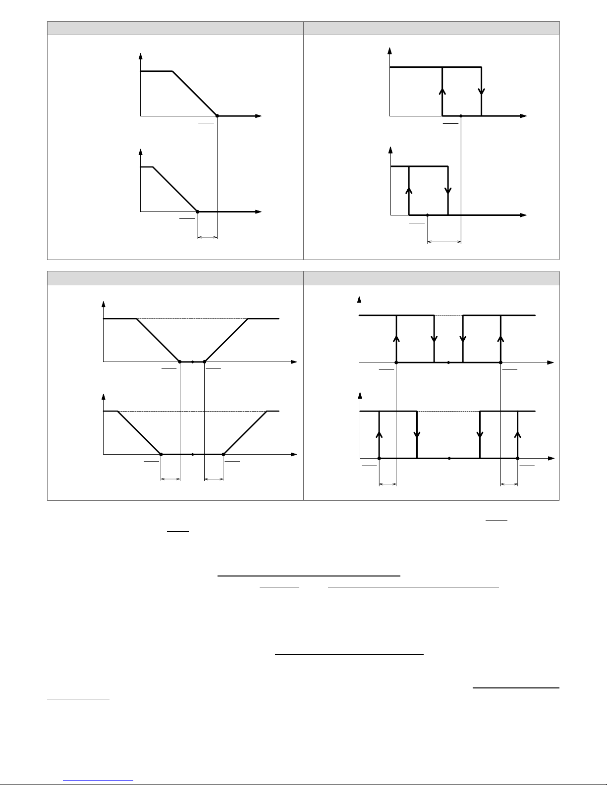
• EC motor automatic speed control logic with on/off outputs
Depending on the value of the stage 1 differential, a fan temperature band (FB) is set, within which the fancoil speed can
vary from speeds 1 to 3.
Hysteresis 0.5 - 1.0 °C > 1.0...1.5 °C > 1.5...2.0 °C
FB 2.0 °C 3.0 °C 4.0 °C
ON
OFF
Temp.
HH
(I18)
Output
BHS
(I07)
ECM speed 1
Temp.
FB
Fan
ECM speed 3
(I27 < 100%)
DO1
AO1
I27 = 100%
The graph refers to heating mode operation.
Set the EC motor parameters as follows:
- Set the voltage corresponding to the minimum EC motor
speed with parameter I29.
- Set the voltage corresponding to the maximum EC motor
speed with parameter I30.
- Set parameters I32, I33, I34 for speeds 1, 2, 3 respectively.
Example: if I29=1V, I30=8V and I32=10%, speed 1 cor-
responds to 1.7V → [I32 x (I30 - I29) + I29]
Automatic speed control is linear over the range of speeds 1
to 3, while manual control simply sets a given speed (see
“4.
Quick access parameter setting” page 8
).
To set speed 1 to the minimum EC motor speed, set I32 to 0.
To set speed 3 to the maximum EC motor speed, set
I34 to 100.
To set speed 2 to the midpoint between speeds 1 and 3,
set I33 to 50.
- Set I27 to dene the point at which maximum speed is
reached within the fan band.
N.B.: parameters I25 and I26 are not used in this application.
The activation/deactivation of the fancoil at speed 1 correspond to the activation/deactivation of stage 1.
28/126
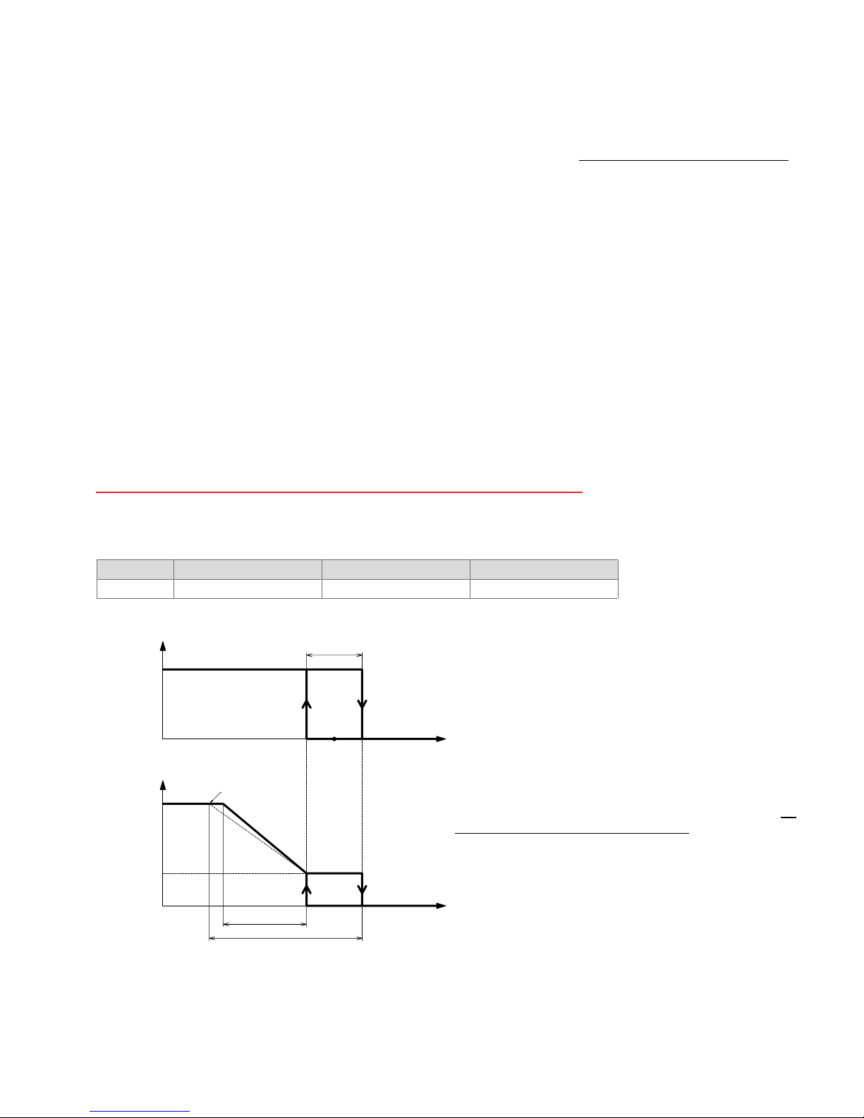
• EC motor automatic speed control logic with 0..10 V modulating outputs
We take the example of control in heating mode.
Temp.
BHS
(I07)
ECM speed 1
% opening valve
Fan
ECM speed 3
PBH
(I22)
(I31)
0%100%
100
0
Output valve
AO1
The graph refers to heating mode.
Set the EC motor parameters as follows:
- Set the voltage corresponding to the minimum EC motor speed with parameter I29.
- Set the voltage corresponding to the maximum EC motor speed with parameter I30.
- Set parameters I32, I33, I34 for speeds 1, 2, 3 respectively.
Example: if I29=1V, I30=8V and I32=10%, speed 1 corresponds to 1.7V → [I32 x (I30 - I29) + I29]
Automatic speed control is linear over the range of speeds 1 to 3, while manual control simply sets a given speed (see
“4. Quick access parameter setting” page 8).
To set speed 1 to the minimum EC motor speed, set I32 to 0.
To set speed 3 to the maximum EC motor speed, set I34 to 100.
To set speed 2 to the midpoint between speeds 1 and 3, set I33 to 50.
- Set parameter I31 to determine the point at which the motor starts in relation to the valve's opening percentage.
This enables the fan to start when water is already circulating in the fancoil coil.
Example: if I31=5%, the motor starts when the valve's modulating output exceeds 0.5V → [I31*10 V]. The fan stops
when the valve closes.
N.B.: parameters I24, I25 and I26 are not used in this application.
29/126
17. Fancoil with 3 speed on-off motor (models TH-2xxSx1, TH-3xxSx1,
TH-4xxSx1)
Parameter M13=1.
The device can control 3 speed on-off fancoils. Parameter M14 is not considered in this case.
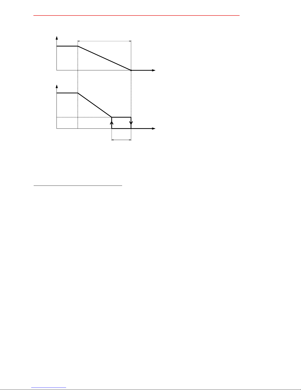
• 3 speed on-off motor speed control logic with on/off outputs
Depending on the value of the stage 1 differential, a fan temperature band (FB) is set, within which the fancoil speed can
vary from speeds 1 to 3.
Hysteresis 0.5 - 1.0 °C > 1.0...1.5 °C > 1.5...2.0 °C
FB 2.0 °C 3.0 °C 4.0 °C
speed 1
Fan
speed 3
BHS
(I07)
speed 2
(I26)
(I27)
ON
OFF
Temp.
HH
(I18)
Output
Temp.
FB
The graph refers to heating mode operation.
Set the 3 speed on-off motor parameters as follows:
- Set parameters I26, I27 to dene the activation points of
speeds 2 and 3 within the fan band.
Example: if Stage 1 hysteresis=0.5°C, FB=2°C and I26=50%,
I27=100%, then speed 2 starts at 0.75°C → [I26 x (FB - hys-
teresis)] below the activation point of speed 1 and speed 3
starts 1.5°C → [I27 x (FB - hysteresis)] below the activation
point of speed 1.
The hysteresis of speeds 2 and 3 corresponds to 20% of the
FB band.
The activation/deactivation of speed 1 correspond to the activation/deactivation of stage 1.
N.B.: parameters I25, I29 and I34 are not used in this application.
• 3 speed on-off motor speed control logic with 0...10V modulating outputs
We take the example of control in heating mode.
speed 1
% opening
valve
Fan
speed 3
(I25)
0%100%
BHS
(I07)
speed 2
(I26)
(I27)
Set the 3 speed on-off motor parameters as follows:
- Set parameters I25, I26 and I27 to dene the activation points of speeds 1, 2 and 3 in relation to the valve opening.
Example: with I25=5%, I26=50%, I27=100%
speed 1 starts when the valve is at ≥ 5% of its total aperture.
speed 2 starts when the valve is at ≥ 50% of its total aperture.
speed 3 starts when the valve is at ≥ 100% of its total aperture.
Speed 1 is deactivated when the valve is closed.
The hysteresis of speeds 2 and 3 corresponds to 20% of the respective activation point.
In the above example:
30/126
speed 2 deactivates when the valve is at ≤ 40% (50% - 20% of 50) of its total aperture.
speed 3 deactivates when the valve is at ≤ 80% (100% - 20% of 100) of its total aperture.
N.B.: parameters I29 to I34 are not used in this application.
18. Manual speeds and ventilation maintenance with no control
The regulation speed type can be selected automatically or manually, at speeds 1, 2 and 3. To see how to select the type of
ventilation, see “Fancoil operating mode” page 9.
If the regulation speed is manual, it stays at the set speed once started throughout regulation.
When it reaches the setpoint, the fan stops if I28=0.
You can keep speed 1 active or the manual speed selected, regardless of the type of speed used in regulation, even if the
regulation itself does not require it. This maintains constant ventilation to keep the air circulating.
To keep speed 1 active in cooling without regulation, set I28=2.
To keep speed 1 active in heating without regulation, set I28=3.
To keep speed 1 active regardless of the season and without regulation, set I28=1.
To keep manual speed selected active in cooling without regulation, set I28=5.
To keep manual speed selected active in heating without regulation, set I28=6.
To keep manual speed selected active regardless of the season and without regulation, set I28=4.
To stop ventilation once the setpoint is reached, set I28=0.
19. Fan boost
The boost function eliminates the problem of incorrect motor starting at low speeds.
Set I37=1, this starts the motor at maximum speed for 1 second, after which it runs at the regulation speed.
If this option is not wanted, set I37=0.
When I37=0, the motor starts directly at the regulation speed.
20. Minimum thermostat
In all heating modes, when a digital input is set as minimum thermostat (M03=6 or M05=6) or remote sensor is congured as
minimum thermostat M07=2 or M09=2 or M11=2, ventilation does not start until the minimum thermostat is closed.
For digital contacts, the minimum thermostat is considered closed, in relation to the position of the contact and the digital
contact logic (see “10. Digital and analogue input logic” page 20).
For the analogue inputs, the logic is as follows:
Minimum
thermostat
open
Minimum
thermostat
closed
I17 -
2°C
I17
Temp.
water coil
On startup, if the temperature of the heating coil is between I17 and I17 - 2, the minimum thermostat is deemed to be open.
Icons , and turn on in sequence when the minimum thermostat is open during heating mode without electric resistance.
N.B.: if the electric resistance is present, the minimum thermostat function is not considered. The fan is activated immediately
when the electric resistance is activated even if the minimum thermostat is considered to be open.
If no regulation is present or in cooling mode, the minimum thermostat is not considered.
 Loading...