

Product
Manual
The Essential Guide for
Safety Teams and
Instrument Operators
Edition 3
March 23, 2016
Part Number: 17156830-1

Industrial Scientific Corporation, Pittsburgh, PA USA
Industrial Scientific Co., Ltd. Shanghai, China
© 2015, 2016 Industrial Scientific Corporation
All rights reserved. Published 2016.
Revision 1
www.indsci.com/ventispro

Contents
General Information .......................................................................................................................................................................... 1
Certifications ................................................................................................................................................................................. 1
Warnings and Cautionary Statements .......................................................................................................................................... 2
Recommended Practices .............................................................................................................................................................. 4
Instrument Maintenance ........................................................................................................................................................... 4
First Use .................................................................................................................................................................................... 5
Wearing the Instrument ............................................................................................................................................................. 5
Remote Sampling ..................................................................................................................................................................... 6
Cold-weather Operation ............................................................................................................................................................ 6
Product Information ........................................................................................................................................................................... 7
Overview ....................................................................................................................................................................................... 7
Key Features ................................................................................................................................................................................. 7
Compatibility ................................................................................................................................................................................. 8
Sensors ..................................................................................................................................................................................... 8
Batteries .................................................................................................................................................................................. 10
Specifications .............................................................................................................................................................................. 11
Instrument ............................................................................................................................................................................... 11
Battery Specifications ............................................................................................................................................................. 12
Sensor Specifications ............................................................................................................................................................. 12
Getting Started ................................................................................................................................................................................ 21
Unpacking the Instrument ........................................................................................................................................................... 21
Hardware Overview .................................................................................................................................................................... 22
Display Overview ........................................................................................................................................................................ 24
Power On .................................................................................................................................................................................... 30
Power Off .................................................................................................................................................................................... 33
Settings ........................................................................................................................................................................................... 35
Guidelines ................................................................................................................................................................................... 35
Accessing and Protecting Settings ............................................................................................................................................. 35
Settings Menus ........................................................................................................................................................................... 36
Examples for Working in Settings ............................................................................................................................................... 36
Reviewing and Editing Settings .................................................................................................................................................. 38
Maintenance menu ................................................................................................................................................................. 39
Start-up menu ......................................................................................................................................................................... 41
Operation menu ...................................................................................................................................................................... 42
Alarm menu ............................................................................................................................................................................. 43
Sensor menu ........................................................................................................................................................................... 45
Admin Menu ............................................................................................................................................................................ 46
Operation ........................................................................................................................................................................................ 49

The Instrument Buttons ............................................................................................................................................................... 49
The Instrument Display ............................................................................................................................................................... 50
Operating the Instrument ............................................................................................................................................................ 50
Information .............................................................................................................................................................................. 50
Utilities .................................................................................................................................................................................... 50
Wearing the Instrument ............................................................................................................................................................... 52
Alarms and Warnings At-a-glance .............................................................................................................................................. 52
Alarms ..................................................................................................................................................................................... 52
Warnings ................................................................................................................................................................................. 53
User-site Assignments ................................................................................................................................................................ 54
Alarms, Warnings, and Other Notifications ..................................................................................................................................... 55
Overview ..................................................................................................................................................................................... 55
Alarms ......................................................................................................................................................................................... 55
Warnings ..................................................................................................................................................................................... 58
Indicators .................................................................................................................................................................................... 59
Failures and Errors ..................................................................................................................................................................... 59
Maintenance ................................................................................................................................................................................... 61
Guidelines ................................................................................................................................................................................... 61
Process At-a-glance .................................................................................................................................................................... 61
Supplies and Preparation ............................................................................................................................................................ 62
Instruction ................................................................................................................................................................................... 63
Service and Warranty ..................................................................................................................................................................... 67
Service ........................................................................................................................................................................................ 67
Guidelines ............................................................................................................................................................................... 67
Supplies .................................................................................................................................................................................. 67
Instruction ............................................................................................................................................................................... 68
Warranty ..................................................................................................................................................................................... 77
Limitation of Liability ................................................................................................................................................................ 77
Assignments ................................................................................................................................................................................... 79
Introduction ................................................................................................................................................................................. 79
iAssign Overview ........................................................................................................................................................................ 79
Procedures .................................................................................................................................................................................. 81
Appendix ......................................................................................................................................................................................... 85
Supplemental Information about Gases and Sensors ................................................................................................................ 85
Toxic Gases ............................................................................................................................................................................ 85
Combustible Gases ................................................................................................................................................................. 86
Contact Information ....................................................................................................................................................... Back cover90

Tables and Figures
Table 1.1 Hazardous area certifications ........................................................................................................................................... 1
Table 1.2 Wireless certifications ....................................................................................................................................................... 2
Table 1.3 Warnings and cautionary statements ................................................................................................................................ 2
Table 1.4 Recommended frequencies for instrument maintenance ................................................................................................. 5
Figure 2.1.A Sensor compatibility and installation locations for the Ventis Pro4 .............................................................................. 9
Figure 2.1.B Sensor compatibility and installation locations for the Ventis Pro5 .............................................................................. 9
Table 2.1 Sensor compatibility and installation locations................................................................................................................ 10
Table 2.2 Battery compatibility ........................................................................................................................................................ 10
Table 2.3 Instrument and pump specifications ............................................................................................................................... 11
Table 2.4 Battery specifications ...................................................................................................................................................... 12
Table 2.5 Sensor specifications ...................................................................................................................................................... 13
Table 3.1 Package contents ........................................................................................................................................................... 21
Figure 3.1.A Hardware overview diffusion instrument .................................................................................................................... 22
Figure 3.1.B Hardware overview aspirated instrument ................................................................................................................... 23
Figure 3.2.A Reading the display during operation ......................................................................................................................... 25
Figure 3.2.B Reading the display during an event (warning or alarm) ............................................................................................ 26
Figure 3.2.C Reading the display during maintenance ................................................................................................................... 27
Figure 3.2.D Reading the display while working in settings ............................................................................................................ 28
Figure 3.3 Power on ........................................................................................................................................................................ 32
Figure 3.4 Power off ........................................................................................................................................................................ 33
Table 4.1 Settings menus ............................................................................................................................................................... 36
Figure 4.1.A Example for editing a single-item setting .................................................................................................................... 37
Figure 4.1.B Example for editing a multi-item setting ..................................................................................................................... 38
Figure 4.2.A Navigating and using maintenance options................................................................................................................ 40
Figure 4.2.B Navigating and editing start-up settings .................................................................................................................... 41
Figure 4.2.C Navigating and editing operation settings ................................................................................................................. 43
Figure 4.2.D Navigating and editing alarm settings ....................................................................................................................... 44
Figure 4.2.E Navigating and editing sensor settings...................................................................................................................... 45
Figure 4.2.F Navigating and editing admin settings ....................................................................................................................... 47
Figure 5.1 Using the buttons during operation ................................................................................................................................ 49
Figure 5.2 Home ............................................................................................................................................................................. 50
Figure 5.3 Operation instruction ...................................................................................................................................................... 51
Figure 5.4 Using iAssign tags ......................................................................................................................................................... 54
Table 6.1 Alarm events (list) ........................................................................................................................................................... 56
Figure 6.1 Alarm events (display screens) ...................................................................................................................................... 57
Table 6.2 Warning events (list) ....................................................................................................................................................... 58
Figure 6.2 Warning events (display screens) .................................................................................................................................. 59
Table 6.3 Failures and errors .......................................................................................................................................................... 59
Table 6.4 Critical errors ................................................................................................................................................................... 60

Figure 7.1 Maintenance supplies and preparation .......................................................................................................................... 62
Table 7.1 Calibration failure: possible causes and recommendations ............................................................................................ 66
Figure 8.1 Instrument diagram ....................................................................................................................................................... 68
Figure 8.2 Pump module diagram .................................................................................................................................................. 69
Table 8.1 Instrument and pump module parts list ........................................................................................................................... 69
Figure 8.3 Service Tasks ................................................................................................................................................................ 76
Table 9.1 iAssign functionality ........................................................................................................................................................ 82
Table A.1 Cross-sensitivity guidelines (%) ..................................................................................................................................... 85
Table A.2 LEL correlation factors for the sensors 17155304-K, -L, and -M ................................................................................... 86
Table A.3 LEL correlation factorsa for the sensor 17155304-U ..................................................................................................... 87

General Information
Certifications
Warnings and Cautionary Statements
Recommended Practices
Table 1.1 Hazardous area certifications
Certifying Body
(CB)
Area Classifications or Identification Number
Approved
Temperature Range
ATEX
Equipment Group and Category II 1G, Ex ia IIC, with the protection
category Ga, in the Temperature Class T4
Equipment Group and Category II 2G, Ex d ia IIC, with the protection
category Gb, in the Temperature Class T4, with IR sensor
-40 °C to +50 °C
(-40 °F to +122 °F)
CSAa
Class I, Division 1, Groups A, B, C, and D, in the Temperature Class T4
Class I, Zone 1, Ex d ia IIC, in the Temperature Class T4
-40 °C to +50 °C
(-40 °F to +122 °F)
C22.2 No. 152 applies to %LEL reading for the sensor Part Number
17155304-M only
-20 °C to +50 °C
(-4 °F to +122 °F)
IECEx
Class I, Zone 0, Ex ia IIC, with the protection technique Ga, in the
Temperature Class T4
Class I, Zone 1, Ex d ia IIC, with the protection technique Gb, in the
Temperature Class T4, with IR sensor
-40 °C to +50 °C
(-40 °F to +122 °F)
UL
Class I, Division 1, Groups A, B, C, and D, in the Temperature Class T4
Class II, Division 1, Groups E, F, and G, in the Temperature Class T4
Class I, Zone 0, AEx ia IIC, in the Temperature Class T4
Class I, Zone 1, AEx d ia II C, in the Temperature Class T4, with IR sensor
-40 °C to +50 °C
(-40 °F to +122 °F)
1
Certifications
Instrument certifications at the time of this document's publication are listed below in Tables 1.1 and 1.2.
a
The following apply to instruments that are to be used in compliance with the CSA certification: Ventis Pro4 and Ventis Pro5 instruments are
CSA certified according to the Canadian Electrical Code for use in Class I, Division 1 and Class I, Zone 1 Hazardous Locations within an
ambient temperature range of T
: -40 °C to +50 °C.
amb

Table 1.2 Wireless certifications
Agency
Identification
FCC
PHH-VPX
IC
20727-VPX
Table 1.3 Warnings and cautionary statements
If it appears that the instrument is not working correctly, immediately contact Industrial Scientific.
Only qualified personnel should operate, maintain, and service the instrument.
Substitution of components may impair intrinsic safety, which may cause an unsafe condition.
Substituer des composants peut compromettre la sécurité intrinsèque, ce qui peut résulter en une situation
dangereuse.
Do not use in oxygen-enriched atmospheres. If the atmosphere becomes oxygen enriched, it may cause
inaccurate readings.
Oxygen-deficient atmospheres may cause inaccurate readings.
A rapid increase in a gas reading that is followed by a declining or erratic reading may indicate an over-range
condition, which may be hazardous.
Sudden changes in atmospheric pressure may cause temporary fluctuations in gas readings.
Temperatures below -20 °C (-4 °F) are likely to cause decreased functionality in the instrument's display screen
and man-down feature.
Sudden changes in ambient-air temperature will cause a form of sensor drift in the Carbon Monoxide/Hydrogen
Sulfide (CO/H2S) sensor (part number 17155306-J) that will produce temporary variations in the sensor's
readings:
If the temperature suddenly increases, the CO reading will temporarily decrease and the H
2
S reading may
temporarily increase.
CSA has assessed only the %LEL combustible gas detection portion of this instrument (the sensor part number 17155304-M only) for
performance according to CSA Standard C22.2 No. 152. Within an ambient temperature range of T
±3%. Within an ambient temperature range of T
been calibrated to 50% LEL CH
CAUTION: CSA C22.2 No. 152 requires before each day’s usage, sensitivity must be tested on a known concentration of pentane or
methane equivalent to 25% or 50% of full scale concentration. Accuracy must be within -0% to +20% of actual concentration. Accuracy
may be corrected by referring to the zero and calibration section of the Product Manual.
ATTENTION : CSA C22.2 N°152 exige que la sensibilité de l’instrument soit testée avant l’utilisation quotidienne de l’instrument sur une
concentration connue de pentane ou de méthane équivalente à 25 % ou 50 % de la concentration totale. L'exactitude doit être entre -0 %
et +20 % de la concentration réelle. L’exactitude peut être corrigée en se référant à la partie concernant la mise à zéro et l’étalonnage
dans le Manuel du produit.
4.
: -20°C up to 0°C, the accuracy is ±5%. This is applicable only when the monitor has
amb
: 0 °C to +50 °C, the accuracy is
amb
Warnings and Cautionary Statements
Read and understand this Product Manual before operating or servicing the instrument. Failure to perform
certain procedures or note certain conditions—provided below and throughout the manual—may impair the
performance of the product, cause unsafe conditions, or both.
2

Table 1.3 Warnings and cautionary statements
If the temperature suddenly decreases, the CO reading will temporarily increase and the H
2
S reading may
temporarily decrease.
The readings will stabilize when the sensor has acclimated to the change in temperature. For example, if the
ambient-air temperatures changes from a "room temperature" of 20 °C (68 °F) to an outdoor temperature of 0
°C (32 °F), the stabilization time is approximately 15 minutes; with smaller or larger changes in temperature,
stabilization time will be shorter or longer, respectively.
Note: If the sensor is to be zeroed after a sudden change in ambient-air temperature, allow the sensor and its
readings to stabilize before zeroing.
To avoid potentially inaccurate readings for some applications—monitoring for gases other than O2, CO, CO2,
H2S, and combustible gases [LEL/CH4]—only use a leather case as a carrying case. Do not power on, operate,
or power off the instrument while it is in a leather case.
Silicone and other known contaminants may damage the instrument’s combustible gas sensors, which can
cause inaccurate gas readings.
To support accurate readings, keep clean and unobstructed all filters, sensor ports, water barriers, and pump
intake port.
Charge the instrument’s battery only in nonhazardous locations using compatible accessories from Industrial
Scientific.
Chargez la batterie de l’instrument uniquement dans des lieux sans danger.
Perform all instrument service tasks and maintenance procedures in nonhazardous locations only. This
includes the removal, replacement, or adjustment of any part on or inside the instrument or its pump.
Exécutez toutes les procédures de service les tâches de service sur l’instrument uniquement dans des lieux
sans danger. Ceci comprend la dépose d’une pièce positionnée sur l’instrument ou à l’intérieur de celui-ci, ou
bien la rechange ou le réglage d’une telle pièce.
Battery contacts are exposed on battery packs when they are removed from the instrument. Do not touch the
battery contacts and do not stack battery packs on top of each other.
Do not use solvents or cleaning solutions on the instrument or its components.
This equipment has been tested and found to comply with the limits for a Class A digital device, pursuant to part
15 of the FCC Rules. These limits are designed to provide reasonable protection against harmful interference
when the equipment is operated in a commercial environment. This equipment generates, uses, and can radiate
radio frequency energy and, if not installed and used in accordance with the instruction manual, may cause
harmful interference to radio communications. Operation of this equipment in a residential area is likely to cause
harmful interference in which case the user will be required to correct the interference at his own expense.
The instrument complies with part 15 of the FCC Rules. Operation is subject to the following two conditions:
This device may not cause harmful interference.
This device must accept any interference received, including interference that may cause undesired
operation.
Changes or modification made that are not expressly approved by the manufacturer could void the user’s
authority to operate the equipment.
This device complies with Industry Canada license-exempt RSS standard(s). Operation is subject to the
following two conditions: (1) this device may not cause interference, and (2) this device must accept any
interference, including interference that may cause undesired operation of the device.
Le présent appareil est conforme aux CNR d'Industrie Canada applicables aux appareils radio exempts de
3

Table 1.3 Warnings and cautionary statements
licence. L'exploitation est autorisée aux deux conditions suivantes : (1) l'appareil ne doit pas produire de
brouillage, et (2) l'utilisateur de l'appareil doit accepter tout brouillage radioélectrique subi, même si le brouillage
est susceptible d'en compromettre le fonctionnement.
Recommended Practices
Instrument Maintenance
The procedures defined below help to maintain instrument functionality and support operator safety.
Industrial Scientific minimum-frequency recommendations for these procedures are summarized below in
Table 1.4. These recommendations are provided to help support worker safety and are based on field data,
safe work procedures, industry best practices, and regulatory standards. Industrial Scientific is not
responsible for determining a company’s safety practices or establishing its safety policies, which may be
affected by the directives and recommendations of regulatory groups, environmental conditions, operating
conditions, instrument use patterns and exposure to gas, and other factors.
Settings
Settings control how an instrument will perform. They are used to help ensure the instrument is in
compliance with company safety policy and applicable regulations, laws, and guidelines as issued by
regulatory agencies and government or industry groups.
Utilities
Maintenance procedures are known as "utilities". Utilities are used to test the instrument or its components
for functionality or performance, or to clear an instrument's summary readings. Each utility is defined below.
Self-test.
The self-test is used to test the functionality of the instrument’s memory operations, battery, display screen,
and each alarm signal type (audible, visual, and vibration).
Bump Test (or "functional test").
Bump testing is a functional test in which an instrument's installed sensors are to be briefly exposed to (or
“bumped” by) calibration gases in concentrations that are greater than the sensors’ low-alarm setpoints.
This will cause the instrument to go into low alarm and will indicate which sensors pass or fail this basic test
for response to gas.
Zero.
Zeroing adjusts the sensors’ “baseline” readings, which become the points of comparison for subsequent
gas readings. During zeroing, the installed sensors are to be exposed to an air sample from a zero-gradeair cylinder or ambient air that is known—by the instrument user—to be clean air. The instrument makes no
judgement about the quality of the zero-air sample; its only task is to read that air sample as clean air.
Zeroing is also a prerequisite for calibration.
4

Table 1.4 Recommended frequencies for instrument maintenance
Procedure
Recommended minimum frequency
Settings
Before first use, when an installed sensor is replaced, and as needed.
Calibrationa
Before first use and monthly thereafter.
Bump testb
Before first use and prior to each day’s use thereafter.
Self-testc
As needed.
Calibration.
Regular calibrations promote the accurate measurement of gas concentration values. During calibration, an
instrument’s installed sensors are to be exposed to their set concentrations of calibration gases. Based on
the sensors’ responses, the instrument will self-adjust to compensate for declining sensor sensitivity, which
naturally occurs as the installed sensors are used or “consumed”.
Note: During calibration, the span reserve percentage value for each sensor is displayed. An indicator of a sensor's remaining
life, when the value is less than 50%, the sensor will no longer pass calibration
Summary Readings.
The time-weighted average (TWA), short-term exposure limit (STEL), and peak readings can each be
"cleared". When any summary reading is cleared, its value is reset to zero and its time-related setting is
also reset to zero.
a
Between regular calibrations, Industrial Scientific also recommends a calibration be performed immediately following each of these incidences:
the unit falls, is dropped, or experiences another significant impact; is exposed to water; fails a bump test; or has been exposed to an overrange (positive or negative) gas concentration. A calibration is also recommended after the installation of a new (or replacement) sensor.
b
When redundant sensors are operating on DualSense® technology, bump testing these sensors may be done less frequently based on
company safety policy.
c
The instrument performs a self-test during power on. For an instrument that is set for always-on, the instrument will automatically perform a
self-test every 24 hours. The self-test can also be completed on demand by the instrument user.
Note: The use of calibration gases not provided by Industrial Scientific may void product warranties and limit potential liability claims.
First Use
To prepare the Ventis Pro Series instrument for first use, qualified personnel should ensure the following
are completed:
Charge the battery.
Review instrument settings and adjust them as needed.
Calibrate the instrument.
Complete a bump test.
Wearing the Instrument
Based on the U.S. Department of Labor's Occupational Safety and Health Administration (OSHA) definition
of the breathing zone, it is recommended that the instrument be worn within a 25.4 cm (10") radius of the
nose and mouth. Refer to OSHA and to other agencies or groups as needed for additional information.
5

Remote Sampling
When sampling with the aspirated instrument, allow time for the air sample to reach the sensors and for the
sensors to respond to any gases that are present. Industrial Scientific recommends the allowance of two
minutes plus two seconds for each foot of sample tubing.
Cold-weather Operation
Use caution when operating the instrument in temperatures below -20 °C (-4 °F), which can diminish
display-screen legibility and man-down functionality. To help support functionality and available battery
power, the following practices are recommended.
Do not operate the instrument in temperatures that are not within the temperature ranges of the
installed sensors (see "Table 2.5, Sensor specifications").
Use a compatible, fully charged extended-run-time battery.
Before using the instrument in the cold-weather environment, power it on a warm-up environment
(approximately 20 °C [68 °F]).
Alternately operate the instrument in the cold-weather and warm-up environments.
Do not operate the instrument unmanned.
6

Product Information
Overview
Key Features
Sensor Compatibility
Specifications
2
Overview
The Ventis™ Pro Series portable gas monitors are used for personal protection to monitor for oxygen and a
variety of toxic gases and combustible gases.
Eleven compatible sensors are available for use with the Ventis™ Pro4 Multi-Gas Monitor, which can
provide readings for up to four gases. These sensors are among the 16 available for use with the Ventis™
Pro5 Multi-Gas Monitor, which can provide readings for up to five gases.
The instruments take gas readings every second and record readings-related data every ten seconds. Data
are stored in the instrument data log, which has these characteristics:
Capacity for approximately three months of readings for a unit that is on 10 hours a day and has four
installed, operational sensors
Data storage for up to 60 alarm events, 30 error events, and 250 manual calibrations and bump tests
Downloadable using compatible accessories that are supported by iNet®, DSSAC, or Accessory
Software from Industrial Scientific.
Ventis™ Pro Series instruments use a multisensory alarm-warning-indicator system comprising audible,
visual, and vibration signals.
The instrument's display-screen language can be set for English, French, German, or Spanish.
Key Features
These communication-enhancing features support operator safety:
Using iNet, DSSAC (Docking Station Software Admin Console), or Accessory Software, the safety
team can provide instrument operators with customized on-screen messages. The options include a
message that displays during the start-up sequence and those that display during gas events. A unique
instructional message can be set for each of these events for each sensor: gas present (alert, low
alarm, and high alarm), STEL, and TWA. the messaging options provide a total of 26 opportunities for
the safety team to communicate specific instructions to the instrument operator.

The panic button provides instrument operators with the ability to turn on (and off) the instrument’s
high-level alarm. This can alert others who are nearby that the instrument operator is in distress,
someone else is in distress, or there is some concern about in-field circumstances.
The man-down feature allows the instrument to sense when it has not moved. A man-down warning or
alarm may indicate the instrument operator is unable to move or press the panic button, or that the
instrument has become separated from its operator. Both the warning and alarm can be turned off by
the instrument operator.
Gas information screens can be set for operation-mode access for the instrument operator who needs
to view setpoints for gas events and calibration gas concentrations.
Several features support safety in ways that encourage operator attention and understanding, or that aid in
the prevention of operator misuse, however unintentional.
The full-screen alarm displays easy-to-read alarm details in “large type”.
The gas-alert feature warns the instrument operator of the presence of gas in concentrations that may
be approaching the instrument’s alarm setpoints. Because it can be reset by the user, the alert also
serves as a form of acknowledgement, prompting the instrument operator to check the display screen
for gas readings and an instructional message, and to optionally turn off the alert.
The alarm-latch feature is used to keep an alarm on after the alarm-causing condition no longer exists.
This serves to sustain alarm signals, which can encourage the instrument operator to check the display
screen for gas readings and an instructional message, and to optionally release the alarm latch.
Programmed iAssign™ tags can be used by the instrument operator to assign an instrument to the
user-site data on his or her tag. This can help promote a sense of ownership among instrument
operators, encouraging their responsible use of the equipment.
When used in combination with the security code feature, the instrument’s always-on option can help
prevent the instrument being powered off during operation.
When the instrument is powered-off, the quick-status feature allows users to view this instrument
information: installed sensors, available battery power, and instrument serial number.
These hardware features help protect and reduce damage to the instrument:
The raised ridge helps shield the sensor ports from dirt and damage when an instrument falls or is
dropped.
The display screen is recessed to protect it from scratches and other damage.
Rails help reduce wear from docking.
Compatibility
Sensors
Each instrument’s compatible sensors can be installed in one or more specific locations as depicted in
Figures 2.1 and 2.2 for Ventis Pro4 and Ventis Pro5, respectively. Table 2.1 provides the same information
but in list format, which is helpful for distinguishing among sensors of the same type. For example, there
are two H2S sensors that do not share installation locations or part numbers.
8

Locations 1 or 2
Hydrogen Sulfide (H2S); 17155304-2
Oxygen (O2); 17155304-3
Location 2 only
LEL (Pentane); 17155304-K
LEL (Methane); 17155304-L
Methane, 0-5% vol; 17155304-M
Locations 3 or 4
Carbon Monoxide (CO); 17155306-1
Carbon Monoxide with low Hydrogen cross-sensitivity (CO/H2 Low); 17155306-G
Hydrogen Cyanide (HCN); 17155306-B
Hydrogen Sulfide (H2S); 17155306-2
Nitrogen Dioxide (NO2); 17155306-4
Sulfur Dioxide (SO2); 17155306-5
Figure 2.1.A Sensor compatibility and installation locations for the Ventis Pro4
Locations 1 or 2
Carbon Monoxide/Hydrogen Sulfide
(CO/H2S); 17155304-J
Hydrogen Sulfide (H2S); 17155304-2
Oxygen (O2); 17155304-3
Location 2 only
Carbon Dioxide/Hydrocarbons (CO2/HC);
17155304-U
Carbon Dioxide/Methane (CO2/CH4);
17155304-V
LEL (Pentane); 17155304-K
LEL (Methane); 17155304-L
Methane, 0-5% vol; 17155304-M
Locations 3 or 4
Ammonia (NH3); 17155306-6
Carbon Monoxide (CO); 17155306-1
Carbon Monoxide/Hydrogen Sulfide (CO/H2S); 17155306-J
Carbon Monoxide with low Hydrogen cross-sensitivity (CO/H2 Low); 17155306-G
Hydrogen Cyanide (HCN); 17155306-B
Hydrogen Sulfide (H2S); 17155306-2
Nitrogen Dioxide (NO2); 17155306-4
Sulfur Dioxide (SO2); 17155306-5)
Figure 2.1.B Sensor compatibility and installation locations for the Ventis Pro5
9

Table 2.1 Sensor compatibility and installation locations
Ventis
Pro4
Ventis
Pro5
Installation
locations
Part number
Sensor
Ammonia (NH3)
No
Yes
3 or 4
17155306-6
Carbon Dioxide/Hydrocarbons (CO2/HC)
No
Yes 2 17155304-U
Carbon Dioxide/Methane (CO2/CH4)
No
Yes 2 17155304-V
Carbon Monoxide (CO)
Yes
Yes
3 or 4
17155306-1
Carbon Monoxide/Hydrogen Sulfide
(CO/H2S)
No
Yes
1 or 2
17155304-J
Carbon Monoxide/Hydrogen Sulfide
(CO/H2S)*
No
Yes
3 or 4
17155306-J
Carbon Monoxide with low Hydrogen
cross-sensitivity (CO/H2 Low)
Yes
Yes
3 or 4
17155306-G
Hydrogen Cyanide (HCN)
Yes
Yes
3 or 4
17155306-B
Hydrogen Sulfide (H2S)
Yes
Yes
1 or 2
17155304-2
Hydrogen Sulfide (H2S)
Yes
Yes
3 or 4
17155306-2
LEL (Methane)
Yes
Yes 2 17155304-L
LEL (Pentane)
Yes
Yes 2 17155304-K
Methane, 0-5% vol
Yes
Yes 2 17155304-M
Nitrogen Dioxide (NO2)
Yes
Yes
3 or 4
17155306-4
Oxygen (O2)*
Yes
Yes
1 or 2
17155304-3
Sulfur Dioxide (SO2)
Yes
Yes
3 or 4
17155306-5
Table 2.2 Battery compatibility
Rechargeable Batteries
Part number
Lithium-ion battery pack
Extended-run-time Lithium-ion
battery
17134453
17148313
Compatibility
Ventis Pro Series diffusion
Yes
Yes
Ventis Pro Series aspirated
No
Yes
*DualSense® technology capable.
Batteries
As shown below, the battery pack is compatible with the diffusion instrument only. The extended run-time
battery can be installed for use with a diffusion or aspirated instrument.
10

Table 2.3 Instrument and pump specifications
Item
Description
Display
Monochrome LCD with automatic backlight
User interface buttons
Three (power button, enter button, and panic button)
Case materials
Polycarbonate with static-dissipative protective rubber overmold
Alarm signals
Visual (two red and two blue lights); audible (95 dB at a distance of 10 cm [3.94 "],
typicala); and vibration
Dimensions
104 x 58 x 36 mm (4.09 x 2.28 x 1 42 ")
Weight
200 g (7.05 oz.), typicalb
Ingress protection
IP68 at 1.5 m (4.9 ′) for one hour
Pump
With 0.3175 cm (0.125 ") inside diameter sample tubing, sustains a continuous sample
draw for up to 30.48 m (100 ').
Temperature range
c and d
-40°C to + 50 °C (-40 °F to + 122 °F)
Humidity ranged
15−95 % relative humidity (RH) noncondensing (continuous)
Specifications
Instrument
The Ventis Pro Series’ instrument specifications are provided below in Table 2.3.
a
May vary based on in-field conditions.
b
May vary based on installed components.
c
Temperatures below -20 °C (-4 °F), can diminish display-screen legibility and man-down functionality. See also "Cold-weather Operation"
(Chapter 1, "Recommended Practices") and Table 1.1, "Certifications".
d
Sensor temperature and humidity ranges may differ from those of the instrument (see "Table 2.5, Sensor specifications").
11

Table 2.4 Battery specifications
Rechargeable Batteries
Part number
Lithium-ion battery pack
Extended-run-time Lithium-ion
battery
17134453
17148313
Llifetime
300 charge cycles
300 charge cycles
Run timea
12 hours
24 hours
Charge timeb
up to 4 hours
up to 7.5 hours
Ambient temperature required for
charging
0 − 40 °C (32 − 104 °F)
0 − 40 °C (32 − 104 °F)
Battery Specifications
Table 2.4 provides battery specifications, which include run time, charge time, charging temperature
requirements, and expected lifetime.
a
Approximate run time when the battery is fully charged and is operating at room temperature.
b
When a lithium-ion battery or battery pack becomes deeply discharged and the instrument is docked, it can take up to an hour for the
instrument display to indicate that the battery is charging.
Sensor Specifications
Table 2.5 provides specifications for each sensor, which include properties, installation locations, operating
conditions, and performance, accuracy, and response-time data.
12

Table 2.5 Sensor specifications
Gas type (abbreviation)
Part number
Ammonia (NH3)
Carbon Dioxide/Hydrocarbons (CO2/HC)
17155306-6
17155304-Uc
Properties
Category
Toxic
Toxic/Combustible
Technology
Electrochemical
Infrared
DualSense™ capable
No
No
Installation location
Ventis Pro4
None
None
Ventis Pro5
3 or 4
2
Operating conditions
Temperature rangea
-20 to +40 °C (-4 to +104 °F)
-20 to +50 °C (-4 to +122 °F)
RH rangea
15-95%
0-95%
Performance
CO2
HC
Sensitivity
Measurement range
0−500 ppm
0-5% vol
0-100% LEL
Measurement resolution
1 ppm
0.01% vol
0.01% LEL
Accuracyc
Calibration gas and
concentration
50 ppm NH3
2.5% vol CO2
25% LEL Propane
Accuracy at time and
temperature of calibration
± 15% (0-100 ppm)
0 to 25% (101−500 ppm)
+10% or 0.1%
+5%
Accuracy over sensor’s full
temperature range
± 15%
+15%
+15%
Response Time
T50
30 s
17 s
17 s
T90
84 s
32 s
35 s
13

Table 2.5 Sensor specifications
Gas type (abbreviation)
Part number
Carbon Dioxide/Methane (CO2/CH4)
17155304-Vc
Properties
Category
Toxic and Combustible
Technology
Infrared
DualSense™ capable
No
Installation location
Ventis Pro4
None
Ventis Pro5
2
Operating conditions
Temperature rangea
-20 to +50 °C (-4 to +122 °F)
RH rangea
0-95%
Performance
CO2
CH4
Sensitivity
Measurement range
0−5% vol
0−5% vol
5.01-100% vol
Measurement resolution
0.01% vol
0.01% vol
0.1% vol
Accuracyc
Calibration gas and
concentration
2.5% vol CO2
2.5% vol
99% vol
Accuracy at time and
temperature of calibration
± 10%
± 10%
± 10%
Accuracy over sensor’s full
temperature range
± 15%
± 15%
__
Response Time
T50
17 s
15 s
15 s
T90
32 s
30 s
30 s
14

Table 2.5 Sensor specifications
Gas type (abbreviation)
Part number
Carbon Monoxide (CO)
Carbon Monoxide and
Hydrogen Sulfide
(CO/H2S)
Carbon Monoxide and
Hydrogen Sulfide
(CO/H2S)
17155306-1
17155306-J
17155304-J
Properties
Category
Toxic
Toxic
Toxic
Technology
Electrochemical
Electrochemical
Electrochemical
DualSense™ capable
No
Yes
No
Installation location
Ventis Pro4
3 or 4
None
None
Ventis Pro5
3 or 4
3 or 4
1 or 2
Operating conditions
Temperature rangea
-40 to +50 °C (-40 to +122
°F)
-20 to +50 °C (-4 to +122 °F)
-20 to +50 °C (-4 to +122 °F)
RH rangea
15-95%
15-95%
15-95%
Performance
CO
H2S
CO
H2S
Sensitivity
Measurement range
0-2000 ppm
0-1500 ppm
0−500 ppm
0-1500 ppm
0−500 ppm
Measurement resolution
1 ppm
1 ppm
0.1 ppm
1 ppm
0.1 ppm
Accuracyc
Calibration gas and
concentration
100 ppm CO
100 ppm CO
25 ppm H2S
100 ppm CO
25 ppm H2S
Accuracy at time and
temperature of calibration
± 5%
± 7%
± 10 %
± 5%
0 to 7%
Accuracy over sensor’s
full temperature range
± 10%
± 5%
± 10%
± 5%
± 10%
Response Time
T50
10 s
15 s
10 s
15 s
10 s
T90
20 s
35 s
20 s
35 s
20 s
15

Table 2.5 Sensor specifications
Gas type (abbreviation)
Part number
Carbon Monoxide with low Hydrogen
cross-sensitivity (CO/H2 Low)
Hydrogen Cyanide (HCN)
17155306-G
17155306-B
Properties
Category
Toxic
Toxic
Technology
Electrochemical
Electrochemical
DualSense™ capable
No
No
Installation location
Ventis Pro4
3 or 4
3 or 4
Ventis Pro5
3 or 4
3 or 4
Operating conditions
Temperature rangea
-20 to +50 °C (-4 to +122 °F)
-30 to +40 °C (-22 to +104 °F)
RH rangea
15-95%
15-95%
Performance
Sensitivity
Measurement range
0−1000 ppm
0−30 ppm
Measurement resolution
1 ppm
0.1 ppm
Accuracyc
Calibration gas and
concentration
100 ppm CO
10 ppm HCN
Accuracy at time and
temperature of calibration
± 5% (0-300 ppm)
± 15% (301-10000 ppm)
0 to10%
Accuracy over sensor’s
full temperature range
± 15%
± 15%
Response Time
T50
8 s
15 s
T90
12 s
50 s
16

Table 2.5 Sensor specifications
Gas type (abbreviation)
Part number
Hydrogen Sulfide (H2S)
Hydrogen Sulfide (H2S)
17155304-2
17155306-2
Properties
Category
Toxic
Toxic
Technology
Electrochemical
Electrochemical
DualSense™ capable
No
No
Installation location
Ventis Pro4
1 or 2
3 or 4
Ventis Pro5
1 or 2
3 or 4
Operating conditions
Temperature rangea
-40 to +50 °C (-40 to +122°F)
-40 to +50 °C (-40 to +122°F)
RH rangea
15-95%
15-95%
Performance
Sensitivity
Measurement range
0−500 ppm
0−500 ppm
Measurement resolution
0.1 ppm
0.1 ppm
Accuracyc
Calibration gas and
concentration
25 ppm
25 ppm
Accuracy at time and
temperature of calibration
± 5% (0-400 ppm)
± 7% (401-500 ppm)
± 7%
Accuracy over sensor’s
full temperature range
± 15%
± 15%
Response Time
T50
10 s
10 s
T90
25 s
25 s
17

Table 2.5 Sensor specifications
Gas type (abbreviation)
Part number
LEL (Methane)
LEL (Pentane)
Methane, 0-5% vol
17155304-Lc
17155304-Kc
17155304-Mc
Properties
Category
Combustible
Combustible
Combustible
Technology
Catalytic bead
Catalytic bead
Catalytic bead
DualSense™ capable
No
No
No
Installation location
Ventis Pro4 2 2
2
Ventis Pro5 2 2
2
Operating conditions
Temperature rangea
-20 to +55 °C (-4 to +131 °F)
-20 to +55 °C (-4 to +131 °F)
-20 to +55 °C (-4 to +131 °F)
RH rangea
15-95%
15-95%
15-95%
Performance
Sensitivity
Measurement range
0−100% LEL
0−100% LEL
0-5% vol
Measurement resolution
1% LEL
1 % LEL
0.01% vol
Accuracyc
Calibration gas and
concentration
50% LEL methane
25% LEL pentane
2.5% vol
Accuracy at time and
temperature of calibration
± 3% LEL (0-50% LEL)
± 5% LEL (51-100% LEL)
± 5% LEL
± 10%
Accuracy over sensor’s
full temperature range
± 15%
± 15%
± 15%
Response Time
T50
7 s
10 s
7 s
T90
10 s
16 s
10 s
18

Table 2.5 Sensor specifications
Gas type (abbreviation)
Part number
Nitrogen Dioxide (NO2)
Oxygen (O2)
Sulfur Dioxide (SO2)
17155306-4
17155304-3
17155306-5
Properties
Category
Toxic
Oxygen
Toxic
Technology
Electrochemical
Electrochemical
Electrochemical
DualSense™ capable
No
Yes
No
Installation location
Ventis Pro4
3 or 4
1 or 2
3 or 4
Ventis Pro5
3 or 4
1 or 2
3 or 4
Operating conditions
Temperature rangea
-20 to +50 °C (-4 to +122 °F)
-20 to +55 °C (-4 to +131 °F)
-20 to +50 °C (-4 to +122 °F)
RH rangea
15-95%
5-95%
15-90%
Performance
Sensitivity
Measurement range
0-150 ppm
0-30% vol
0-150 ppm
Measurement resolution
0.1 ppm
0.1 ppm
0.1 ppm
Accuracyb
Calibration gas and
concentration
25 ppm NO2
20.9% vol O2
10 ppm SO2
Accuracy at time and
temperature of calibration
± 5%
± 0.3% vol
± 5% (0-20 ppm)
0 to 11% (21-150 ppm)
Accuracy over sensor’s
full temperature range
± 15%
± 0.2% vol
± 10%
Response Time
T50
10 s
5 s
10 s
T90
20 s
15 s
25 s
a
During continuous operation.
b
Apply when the instrument is calibrated using the stated calibration gas and concentration; accuracy is equal to the stated percentage or one
unit of resolution, whichever is greater.
c The sensor part number 17155304-M is CSA-assessed for %LEL combustible gas detection. The following sensors are not CSA-assessed
for combustible gas detection: part numbers 17155304-K, 17155304-L, 17155304-U, and 17155304-V.
“—” indicates no available data.
19


Getting Started
Unpacking the Instrument
Hardware Overview
Display Overview
Power On
Power Off
Table 3.1 Package contents
Quantity
Item
Notes
1 as ordered
Ventis Pro Series instrument
Ventis Pro4 or Ventis Pro5.
1 as ordered
Battery (factory installed)
Rechargeable Lithium-ion or Rechargeable Extended-run-time
Lithium-ion.
1
Suspender clip (factory installed)
—
1
Final Inspection & Test Report
Includes informationa about the instrument and its installed
sensors and factory calibration.
1
Reference Guide
Short-form instruction for powering on and using Ventis Pro
Series instruments.
1 as ordered
Ventis Charger
The universal power cord includes four plugs, one each for use
with US, UK, EU, and AUS receptacles.
1
Calibration cup
—
1
Calibration tubing
60.96 cm (2 ') of urethane tubing; 4.762 mm (3/16 ″) ID.
Unpacking the Instrument
3
The items that are shipped with the unit are listed below in Table 3.1. Each item should be accounted for
during the unpacking process. If any item is missing or appears to have been damaged, contact Industrial
Scientific (see back cover) or an authorized distributor of Industrial Scientific products.
a
At the time of shipment.
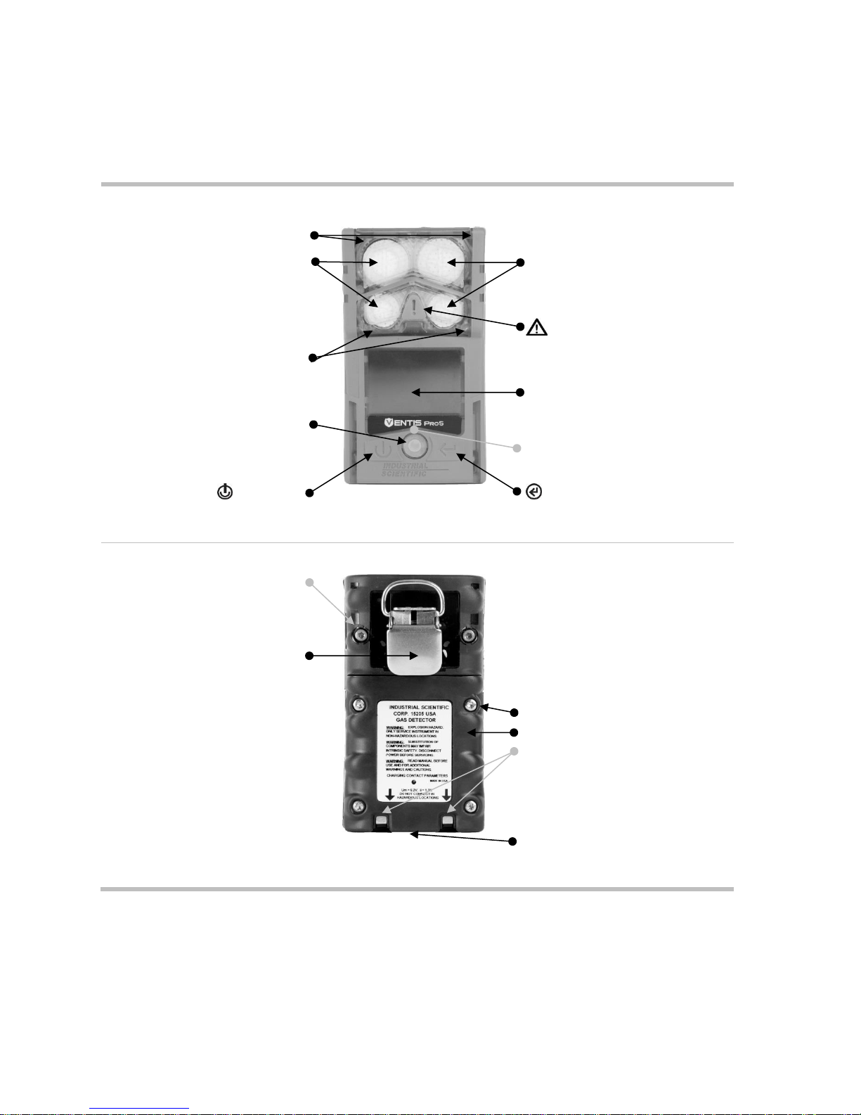
Front
Red lights
Sensor ports
Sensor ports
Panic button
Blue lights
Display screen
Speaker
iAssign™ touch area
Power button
Enter button
Back
Case bottom screw (x2)
Clip
Battery pack screw (x4)
Battery pack
Charging contacts
Infrared data window
Figure 3.1.A Hardware overview diffusion instrument
Hardware Overview
The instrument's main hardware components are identified below in Figures 3.1.A and 3.1.B for the
diffusion and aspirated instruments, respectively (Ventis Pro5 shown).
22

Front
Intake port
Cap
Pump door hinge
Barrel (houses water barrier)
Pump door screw
Pump door
Panic button
Red lights
Blue lights
Speaker
Display screen
iAssign™ touch area
Power button
Enter button
Infrared data window
Back
Pump case
(lower portion houses battery)
Pump case screw (x4)
Figure 3.1.B Hardware overview aspirated instrument
23

Status bar
During operation, the display screen’s
status bar communicates basic
information to the instrument operator:
instrument and battery status (shown),
ambient-air temperature, and the time of
day.
Instrument status symbol
The status bar checkmark indicates the instrument is
operational.
Other symbols
Pump installed.
The battery’s level of charge is between 67and 100%.
The battery’s level of charge is between 34 and 66%.
The battery’s level of charge is less than or equal to 33%.
The battery’s level of charge is approaching a critically low
level.
11:34a
The time of day (12-hour format shown).
76 F
The ambient-air temperature reading (Fahrenheit shown).
Display Overview
The instrument’s easy-to-read display screen has three main horizontal segments. From top to bottom, they
are:
Status bar
Gas readings area
Navigation bar
The instrument uses these areas to display symbols, numbers, abbreviations, and text in combinations that
allow it to clearly communicate with its user: the instrument operator in the field or the safety team
members who are responsible for maintaining the instrument.
See Figures 3.2.A through 3.2.D to become familiar with the display screen layout and content items the
user can expect to see at these times:
During operation
In the event of a warning or alarm
During maintenance
While working in settings
24

Gas readings area
In addition to the display of current gas
readings, this area communicates status
information about the installed sensors.
Gas reading
Gas, unit of measure, and current reading.
Other symbols
The indicated sensor is in a general state of failure.
The indicated sensor failed zeroing.
CAL
The indicated sensor failed calibration.
BUMP
The indicated sensor failed bump testing.
ERR
The indicated sensor is installed in the wrong location.
Navigation Bar
During operation, there may be
information screens or maintenance
utilities available to the instrument
operator. If so, the bottom area of the
display screen will feature the navigation
bar. The action displayed on the left is
controlled by the button underneath it, the
power button ; the action on the right is
controlled by the enter button .
Instructional symbols and text
Start the option (bump test utility shown above).
Skip the option and go to the next display screen.
Clear values.
Figure 3.2.A Reading the display during operation
Clear
25

Status bar
Gas readings area
Full-screen alarm format
In the event of a warning or alarm, the
gas readings area communicates the
event type, details about the alarm, and
gas readings for all sensors.
Event symbols (gas-related)
and
Gas present, over-range alarm
and
Gas present, high-alarm
and
Gas present, low-alarm
Gas present, alert (warning)
Short-term exposure limit (STEL) alarm
Time-weighted average (TWA) alarm
Alarm is latched
Other symbols (nongas-related, full-screen symbol)
Critical low battery
Panic alarm
Man-down alarm
System error (408 shown)
Figure 3.2.B Reading the display during an event (warning or alarm)
26

Status bar
The display screen’s status bar indicates
which maintenance procedure is in
progress (bump test utility shown here).
Utility symbols
Bump test utility
Zero utility
Calibration utility
Process in progress.
Gas readings area
The gas readings area communicates
information about the process and results
for any maintenance procedures (bump
test utility shown here).
Other symbols
Calibration gas type, unit of measure, and concentration
Results
Passed
Failed
Navigation Bar
The navigation bar provides instruction.
The action displayed on the left is
controlled by the button underneath it, the
power button ; the action on the right is
controlled by the enter button .
Instructional symbols
Cancel the utility (bump test shown here).
Start the utility.
Apply the calibration gas.
Figure 3.2.C Reading the display during maintenance
27

Status bar
When working in settings, the status bar
may indicate the setting name (H2S
settings shown here).
Multi-item setting
Single-item setting
Editing area
The editing area displays the settings'
values. The highlight bar indicates which
setting is being edited (gas-alert value
shown here).
Navigation bar
The navigation bar provides instruction for
navigating settings. The action displayed
on the left is controlled by the button
underneath it, the power button ; the
action on the right is controlled by the enter
button .
Status bar symbol
Settings.
Other symbols
Current setting.
Go to the next setting.
Edit the setting.
Edit the setting.
Scroll an options list.
Exit.
X.Y
"X" indicates the display screen's menu number; "Y"
indicates its setting number.
Figure 3.2.D Reading the display while working in settings
Gas names
CH4
CH4 (Methane)
CO
Carbon Monoxide
CO2
CO
2
(Carbon Dioxide)
ON
In addition to the items described above, the Ventis Pro Series’ display will also feature, when relevant, the
gas names, units of measure, and other symbols shown below.
28

H2S
H2S (Hydrogen Sulfide)
HC
Hydrocarbons
HCN
Hydrogen Cyanide
LEL
Combustible gases
NH3
NH3 (Ammonia)
NO2
NO2 (Nitrogen Dioxide)
O2
O2 (Oxygen)
SO2
SO2 (Sulfur dioxide)
Units of measure
ppm
Parts per million.
Mg/M
3
Milligrams per cubic meter.
% LEL
The lower explosive level (LEL) is the minimum concentration of a gas, which, if given an ignition
source, is capable of producing a flash of fire.
% vol
Percent by volume refers to a defined amount of the gas in 100 parts of air. For example, normal air
contains 21% vol oxygen, or 21 parts oxygen in every 100 parts of air.
Other symbols
Yes.
No.
Maintenance due (calibration shown).
The down arrow indicates the number of days since the maintenance procedure was last completed.
The up arrow indicates the number of days until the maintenance procedure is next due.
or
Peak readings.
User assignment.
Site assignment.
Return the instrument to Industrial Scientific.
Security code is required.
Data exchange or synchronization may be in progress.
Indicates that the sensor is operating on DualSense technology.
A sensor that was operating on DualSense has failed.
A sensor operating on DualSense is due for maintenance (sensor 1 shown here).
29

—
—
Attach one end of the sample tubing to the pump inlet's nipple (left); attach the other end
to a compatible water stop (right).
At each end, push on the tubing to ensure the connecting part is fully inserted into the
tubing (approximately .635 cm [.25 "]) . To test for a firm connection, gently pull on the
tubing.
Self-test
Light test
Display test
Audible and vibration test
Sample error message
The blue lights will flash
followed by the red lights.
Verify that all lights are
functional.
Observe the display screen
to verify that all pixels are
functional.
The instrument will vibrate
and then emit a loud beep.
Verify that both signal types
are functional.
If the instrument fails any
part of its self-test, an error
message will display. If the
instrument or its operator
detect problems, contact
Industrial Scientific for
assistance.
Power On
If a pump is installed, complete the following pump preparation steps before powering on the instrument.
If the use of the integrated pump is desired, but has not been installed, see Figure 8.2 Service Tasks.
To power on the instrument, press and hold the power button for approximately three seconds, until the
blue lights flash. The instrument will perform a self-test; its operator should observe the instrument and its
display screen to verify the unit is operating as expected (see Figure 3.3 below).
Immediately following the self-test is the start-up sequence, which will provide information and may prompt
the instrument operator to prepare the instrument for use. Preparation and utility options included in the
start-up sequence may vary from those shown below depending on instrument settings and whether or not
a pump is installed.
At the end of the power on process, the home screen will display.
30

Start-up sequence
Information
Date and time
Instrument information
Regulatory information
Instrument assignments
If the battery has been
reinstalled or replaced, the
instrument operator may be
prompted to set the date
and time, which can be
done manually or by
docking the instrument.
—
—
Indicates the company,
person (user), and location
(site) to which the
instrument is currently
assigned.
Maintenance information
Gas information
—
The dock information (above left) indicates maintenance is
due in the future (“days until”).
The calibration information (above right) indicates when the
maintenance was last performed (“days since”). Calibration
information can also appear as due in the future.
A series of information screens provide the setpoints for
each sensor (H2S shown). The values from left to right are:
Top row: gas present alert, low alarm, and high alarm.
Bottom row: STEL alarm, TWA alarm, and calibration gas
concentration.
Verify that the settings are appropriate.
Preparation and utilities
Start-up message
Compliance check
(German-language instruments
only)
Read and
understand
the
message.
If a pump has been installed, the instrument will prompt its
operator to complete the following pump test.
Acknowl-
edge
message.
Answer "no".
Answer
"yes".
31

Pump test
Block inlet
Wait
—
When prompted, use a thumb to block the end of the sampling
line, the water-stop opening.
While the test is in progress, the display screen will ask the
instrument operator to wait. Next, the test results will be
displayed as "Passed" or "Failed".
Test results: Passed
Test results: Failed*
Remove thumb from the
water-stop opening.
Restart the pump: Press .
It may take several seconds for
the pump to restart.
Remove thumb from the
water-stop opening.
—
Power off the
instrument.
*Note: A failed pump test may indicate a problem somewhere in the sampling line. Check and correct for cracks or other damage, debris, and
improper installation in these areas: all sampling line connections, and the pump's inlet cap, inlet barrel, and dust filter.
Zero utility
Bump test utility
Skip the
utility: wait 15
seconds.
Skip the
utility: wait
15
seconds.
Start the
utility.
Home
No fault status symbol
Home (five-gas instrument)
Battery status (shown), temperature, and time
Gas name
Home (four-gas instrument)
Unit of measure
Current gas reading
Figure 3.3 Power on
32

Home
Countdown
Enter security code
— —
Start power-off
countdown.
Hold for the full
five-second
countdown.
Enter the
diplayed value.
Edit the displayed
value.
Figure 3.4 Power off
When the instrument is powered off, the installed sensors, available battery power,
and instrument serial number can be viewed without powering on the instrument:
simultaneously press and hold and for two seconds.
Power Off
If the instrument is set to remain on, power off may require the entry of the unit’s security code.
Quick-status information
33


Settings
Guidelines
Accessing and Protecting Settings
Settings Menus
Examples for Working in Settings
Reviewing and Editing Settings
—
—
Press
Press
Press
Press
Enter the
displayed
value.
Edit the
value.
Next menu
Start
maintenance
Guidelines
4
Settings that can be adjusted manually through the instrument are described in this Product Manual. These
and other settings can also be adjusted through compatible Industrial Scientific docking stations and
accessories supported by iNet, DSSAC, and Accessory Software; any changes made manually to the
instrument will be overridden when the instrument is docked.
Only qualified personnel should access and adjust instrument settings; this person is referred to below as
the "safety specialist". To help guard against unintended access by nonqualified personnel, settings can be
security-code protected.
Accessing and Protecting Settings
Settings can be accessed while the instrument is powering on—any time during the start-up sequence—by
simultaneously pressing then releasing and . If the security-code screen is activated, settings are
protected and the instrument's security code must be entered. If the entered value matches the
instrument's security code, the first settings menu (1.0 Maintenance) will display; otherwise, access to
settings will be denied and the instrument will resume start-up.

Table 4.1 Settings menus
Menu number and topic
Settings summary
1.0
Maintenance
The primary purpose of the maintenance menu is to provide the safety specialist with
access to maintenance procedures (utilities). The specialist can also control from
here the NFC setting and make user or site assignments.
2.0
Start-up
Start-up settings allow the safety specialist to permit or prohibit all-user access—from
the start-up sequence—to some utilities and maintenance status information (e.g.,
number of days until calibration is due).
3.0
Operation
The operation menu allows the safety specialist to permit or prohibit—during
instrument operation—all-user access to utilities and maintenance status information.
Access is set separately for each item. For example, the option to clear the peak
readings may be permitted for all-user access, but access to calibration may be
prohibited.
From here, the specialist can also permit or prohibit the use of iAssign tags during
instrument operation.
4.0
Alarm
Alarm settings allow the safety specialist to set the values for each gas event that will
cause the instrument to alarm.
The specialist can also permit or prohibit instrument power off during alarms and
make other choices about alarm-related instrument behavior.
5.0
Sensor
Sensor settings allow the safety specialist to view basic information about the
installed sensors and control settings related to calibration and bump test utilities.
6.0
Admin
(Administration)
Admin settings allow the safety specialist to control important aspects about how the
instrument communicates with its operator. For example, a security code can be set
to help restrict all-user access to settings.
The safety specialist can also set the display-screen language, maintenance-related
warnings, and other items.
If the code is unknown, settings can be accessed by invalidating the current security-code setting as
follows: First, edit the displayed security-code value to 412. Then, simultaneously press and release and
. The first settings menu (1.0 Maintenance) will display. The instrument's settings can be returned to a
protected state by setting a new security code (see the settings menu 6.0 Admin).
Settings Menus
A menu system is used to organize instrument settings by topic. This allows the safety specialist to first
choose the menu (topic) of interest, such as alarms, then review and optionally "edit" (adjust) each
available setting within that menu. Table 4.1 summarizes the settings that are available in each menu.
Examples for Working in Settings
Two examples are provided below to illustrate how to navigate in and adjust settings.
Each example includes a goal, a target setting that is to be changed; the navigation path that leads to the
target setting; and instruction to change the target setting.
Example 1 features a single-item setting—a setting that has a value of “on” or “off”.
Example 2 features a multi-item setting where the value for each of several items can be changed—one
item at a time.
36

Press
Go to the next menu
Press
Go to the next menu.
Press
Go to the next menu.
Press
Go to the first setting option
within the alarm menu.
—
Press
Bypass the Audio Alarm
setting.
Press
Bypass the Vibrating Alarm
setting.
Press
Edit the setting: change the
Alarm Latch value from "off"
to "on".
Press
Go to the next setting.
Figure 4.1.A Example for editing a single-item setting
Edit
Example 1. Editing a single-item setting
Goal: Latch the instrument's alarms
From the 1.0 Maintenance menu, navigation leads to the 4.0 Alarm menu where the alarm-latch setting
resides. Along the way, the navigation bypasses menus 1.0, 2.0, and 3.0.
From the 4.0 Alarm menu, navigation leads to the setting, “Alarm Latch”. Along the way, other alarm
settings are bypassed and their values remain unchanged.
At the alarm-latch setting, the value is changed the from “off” to “on”.
Example 2. Editing a multi-item setting
Goal: Change the high-alarm setpoint for H2S.
Follow the navigation from Example 1 above.
The navigation shown below then bypasses setpoints for the O
their values remain unchanged.
The H
S event setpoint screen is a five-item setting. The navigation bypasses the first two settings, the
2
gas-alert and low-alarm setpoints; their values remain unchanged.
The H
S high-alarm setpoint is then highlighted for editing. Its value is changed from 20.0 ppm to 19.0
2
ppm.
37
, LEL, and CO sensors are bypassed;
2

Press
Bypass the settings for O2.
Press
Bypass the settings for
LEL.
Press
Bypass the settings for CO.
Press
Highlight the first setpoint
for H2S (gas alert).
—
Press
Bypass the gas-alert
setting.
Press
Bypass the low-alarm
setting.
Press
Edit the value for the high-
alarm setpoint.
Press the button until the
desired value of 19.0 is
displayed.
Press
Save the new high-alarm
setpoint value; go to the
next H2S setting.
—
—
Press
Bypass the STEL alarm
setting.
Press
Bypass the TWA alarm
setting.
Figure 4.1.B Example for editing a multi-item setting
Reviewing and Editing Settings
The rest of this chapter describes in detail the settings and options available within each menu. Instruction
is provided for navigating each menu and adjusting its settings.
Maintenance
Start-up
Operation
Alarm
Sensor
Admin
When navigating and editing settings, the instrument will wait approximately 60 seconds between button
presses; when no button is pressed, it will exit settings and re-enter start-up. To return to settings from
start-up, simultaneously press and hold, then release and .
38

Maintenance menu
Instrument information
Regulatory information
Dock status
— —
Next menu
Go to the
first
maintenance
option
Next option
Next option
Next option
View span
values
Calibration status
Zero and calibration utilities
Bump test utility
Peak readings
Next option
View span
values
Next option
Start utility
Next option
Start utility
Next option
Clear peak
readings
Maintenance menu
The maintenance menu serves mainly to provide the safety specialist with access to maintenance
procedures (utilities), plus some general information and iAssign-related settings.
Perform any utility:
Zero the installed sensors.
Calibrate the instrument.
Bump test the installed sensors.
View and optionally reset to zero each summary reading (peak, TWA, or STEL reading). When any
summary reading is reset to zero, its time-related setting is also reset to zero.
View and optionally set the instrument's user and site assignments from the list of available values.
Access this information:
The docking or calibration due values, or days since last calibration
The instrument's model, serial number, firmware version, boot loader version, and regulatory
information
39

TWA readings
STEL readings
Near-field communications
(NFC) for iAssign
User Assignment (current user
highlighted)
Next option
Clear TWA
readings
Next option
Clear STEL
readings
Next option
Turn on or
off
Scroll user
list
Set user
Site assignment (current site
highlighted)
End of menu
—
—
Scroll site list
Set site
Revisit
maintenance
options
Go to menus
Figure 4.2.A Navigating and using maintenance options
40

Startup menu
Zero on start-up
Bump test on start-up
Maintenance status on start-
up
Next menu
Go to first
start-up
setting
Next setting
Set access
Next setting
Set access
Next setting
Set access
and format
End of menu
— — —
Revisit start-
up settings
Go to menus
Figure 4.2.B Navigating and editing start-up settings
Start-up menu
Control how the instrument will interact with its operator during start-up: permit or prohibit all-user access to
each of item listed below.
Maintenance utilities:
Zero the installed sensors.
Bump test the installed sensors.
Maintenance status message:
No message
The number of days until the next dock is due
The number of days until the next calibration is due
The number of days since calibration was last performed
41

Operation menu
Instrument assignment
information
Maintenance status
Zero and calibrate
Next menu
Go to first
operation
setting
Next setting
Set all-user
access
Next setting
Set all-user
access and
format
Next setting
Set all-user
access
Clear summary readings
Bump test
Peak readings
TWA and STEL readings
Gas settings information
Next setting
Set all-user
access
Next setting
Set all-user
access
Next setting
Set all-user
access
Next setting
Set all-user
access
Operation menu
Control how the instrument will behave during operation.
Permit or prohibit all-user access, during operation, to each of the items listed below.
Utilities:
o Zero the installed sensors.
o Calibrate the instrument.
o Bump test the installed sensors.
o View and optionally clear each summary reading (peak, TWA, or STEL). Note: When an instrument
operator clears any summary reading, the value is reset to zero and its time-related setting is also
reset to zero.
Information:
o The instrument's current assignments for user, site, or both
o A maintenance message about scheduled docking or calibration activities
o The gas information for all installed sensors: the values for the gas alert and alarm setpoints, and
the calibration gas and concentration
Set this functionality
Permit all-user power off or set the instrument for "always-on" operation*.
Permit or prohibit the use of iAssign tags during operation.
Set the instrument to display the ambient air temperature in Celsius or Fahrenheit.
*Always-on functionality also requires a valid security code setting (see the settings menu 6.0 Admin).
42
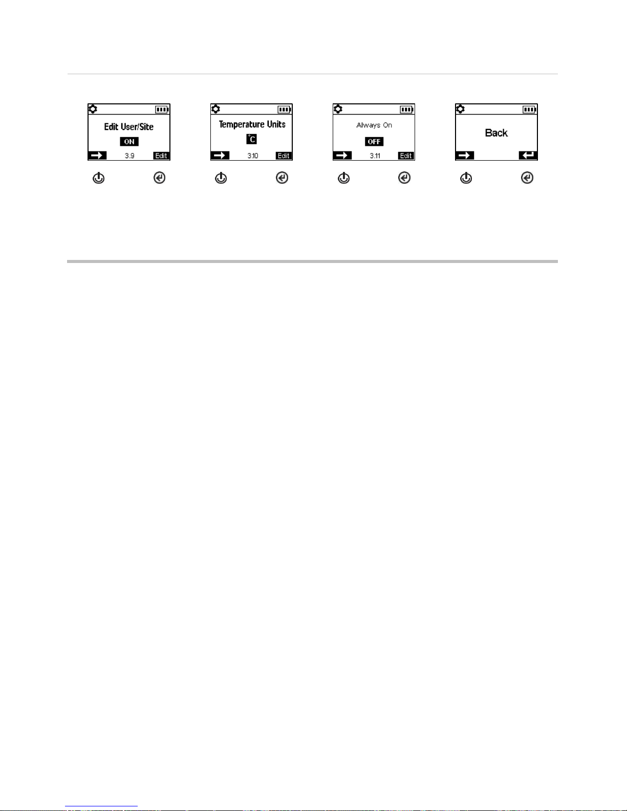
iAssign functionality
Temperature display
Always-on functionality
End of menu
Next setting
Set all-user
functionality
Next setting
Set unit of
measure
Next setting
Set
functionality
Revisit
operation
settings
Access
menus
Figure 4.2.C Navigating and editing operation settings
Alarm menu
Control how the instrument will behave during alarms and some warnings.
Set for each sensor, the concentration of gas that will cause each possible gas event listed below.
gas present, alert
gas present, low-alarm
gas present, high-alarm
TWA
STEL
Note: The navigation will start with the first event setpoint for the first sensor; then the second event
setpoint for that same sensor, and so on through the last setpoint for the sensor. The navigation will
then go through the same pattern for the next sensor.
Set the TWA time interval for toxic sensor readings.
Permit or prohibit instrument power off during alarms.
Set the on-off functionality for the man-down feature; set the amount of time that will lapse between the
man-down warning and its alarm.
Set the on-off functionality for each option listed below.
audible alarm
vibrating alarm
gas-present alert
alarm latch
alarms while docked
43

Alarm menu
Audio alarm
Vibrating alarm
Alarm latch
Next menu
Go to first
alarm setting
Next setting
Turn on or
off
Next setting
Turn on or
off
Next setting
Turn on or
off
Alert and alarm setpoints (H2S shown)
Gas present, alert
Gas present, low alarm
Gas present, high alarm
STEL alarm
Next setting
Edit value
Next setting
Edit value
Next setting
Edit value
Next setting
Edit value
TWA alarm
TWA interval
Shutdown in alarm
Alarm while docked
Next setting
Edit value
Next setting
Edit value
Next setting
Turn on or
off
Next setting
Turn on or
off
Man-down warning and alarm
Gas-present alert
End of alarm settings
—
Next setting
Turn on or
off; edit
delay value
Next setting
Turn on or
off
Revisit alarm
settings
Access
menus
Figure 4.2.D Navigating and editing alarm settings
44

Sensor menu
Installed sensor locations
Span reserve percentage
values
Bump test and calibration
process type
— —
Next menu
Go to first
senor setting
Next setting
Next setting
Next setting
Set for quick
or
independent
Calibration values for LEL
sensor
LEL correlation factor
Calibration gas
concentrations (non-LEL
sensors)
End of menu
Next setting
Edit unit of
measure;
calibration
gas and
concentration
Next setting
Edit value
Next setting
Edit value
Revisit
sensor
settings
Access
menus
Figure 4.2.E Navigating and editing sensor settings
Sensor menu
Control settings related to calibration and bump testing:
Choose the "quick" or "independent" process for calibration and bump testing, choose.
Quick process. This process allows for only one application of gas. It is well suited for installed sensor
combinations that use a calibration gas cylinder of the "blended" type—one that contains the gas types
and concentrations required for all installed sensors.
Independent process. This process for more than one application of gas, and the process allows time—
between gas applications—for the change of cylinders. It is well suited for installed sensor
combinations that require more than one calibration gas cylinders.
Set calibration gas concentrations for each sensor. For LEL sensors, select the unit of measure,
calibration gas type, and correlation factor.
View the location of each installed sensor and its span reserve percentages. Note: An indicator of a
sensor's remaining life, the span reserve percentage will decline over time; when its value is less than 50%,
the sensor will no longer pass calibration.
45

Security code
Confidence indicator
Scheduled maintenance
warnings
Next menu
Go to first
admin
setting
Next setting
Edit value
Next setting
Turn on or
off; set
indicator
type
Next setting
Turn on or
off
Admin Menu
Control the ways in which an instrument will interact with its user and set time-based values that are related
to the data-log entries and bump testing.
To help protect access to settings, set the instrument's security code value to any three-digit number from
001 to 999. A value of 000 will leave settings unprotected and potentially accessible all instrument users.
A security code of 001-999 is also required for the use of always-on functionality; if set to 000, an alwayson unit can be powered off without a security code.
Sensors pass a bump test when they sense the specified percentage of calibration gas (or "pass limit")
within the specified response-time setting. Set the bump test criteria for these two values:
a pass limit value from 50 to 99%
a response-time value from 30 to 120 seconds
Note: For calibration gas recommendations, see "Table 2.5, Sensor specifications".
Turn on or off each of these warnings: scheduled bump test due, scheduled calibration due, and scheduled
dock (or "synch") due. For each warning that is set for on, set these two values:
a warning type of audible only, visual only, or both audible and visual
the maintenance interval (set in one-day increments for dock and calibration and half-day increments
for bump test)
The confidence indicator emits a signal every 90 seconds to indicate to the user and others who are nearby
that the instrument is powered on. If the indicator is set for on, choose a warning type of audible only, visual
only, or both audible and visual.
Set the instrument's display language.
To support data-log integrity, set the date and time; these values are associated with gas-readings and
event data that are saved to the data log.
46

Maintenance intervals
Bump test criteria
Display-screen language
Current date
Next setting
Set interval
(days)
Next setting
Edit
percentage
and time
Next setting
Choose
display-
screen
language
Next setting
Edit values
Current time
End of menu
End of setting
—
Next setting
Edit values
Revisit
sensor
settings
Access
menus
Revisit
settings
Exit settings
Figure 4.2.F Navigating and editing admin settings
47


Operation
The Instrument Buttons
The Instrument Display
Operating the Instrument
Wearing the Instrument
Alarms and Warnings At-a-glance
User-Site Assignments
Panic
Press and hold to turn on (or off) the instrument’s
high-level alarm.
The panic alarm can help alert others nearby of
distress. For example, the instrument operator has
tripped, fallen, been otherwise injured, another
person has been injured, or there is some concern
about in-field circumstances.
Power
Press to view information and access utilities.
Press and hold to power on or off the instrument.
Enter
Press and hold to reset a
latched alarm.
Press to start a utility.
+
To complete an instrument self-test,
simultaneously press and hold, then release
both buttons.
Figure 5.1 Using the buttons during operation
5
The Instrument Buttons
Ventis Pro Series instruments have three buttons, the power button, the enter button, and the panic button.
During operation, the buttons are used as described below in Figure 5.1

No fault status symbol
Home (five-gas instrument)
Battery status (shown), temperature, and time
Gas name
Unit of measure
Current gas reading
Home (four-gas instrument)
Figure 5.2 Home
The Instrument Display
After a unit has been powered on—its self-test and start-up sequence successfully completed—the gas
readings should display. This display screen is referred to as “Home”, which will generally look like the
samples shown below for a five-gas instrument (enlarged for detail) and a four-gas instrument. During
operation, the home screen will display unless the instrument is using the screen to provide information
about an alarm, warning, indicator, or status item, or the instrument operator has accessed another option.
Operating the Instrument
From the home screen, a series of display screens may be accessible depending on the unit’s settings.
Some are information screens and some are utilities.
Information
Information screens display briefly, require no user action, and may include:
Number of days until the instrument is due to be docked.
Number of days until the instrument is due for calibration or the number of days since its last
calibration.
Gas settings information (alert and alarm setpoints and calibration gas concentration for the installed
sensors).
Assignment information (the company, use, and site assigned to the instrument).
Utilities
Utilities give the instrument operator opportunities to complete maintenance procedures, which may
include:
Zero the installed sensors and calibrate the instrument.
Bump test the installed sensors.
50

Home
Docking information
Calibration information
Span reserve
percentage is an indicator of
a sensor's remaining life.
When the value is less than
50%, the sensor will no
longer pass calibration.
—
Next display
screen
Next display
screen
View span
reserve
percentage
values
Next display
screen
View span
reserve
percentage
values
Zero and calibration utilities
Bump test utility
Peak readings
TWA readings
Skip the
utility
Start the
utility
Skip the
utility
Start the
utility
Do not clear
readings
Clear
readings
Do not clear
readings
Clear
readings
STEL readings
Gas information
Assignment information
Home
— —
—
Do not clear
readings
Clear
readings
Next display
screen
Next display
screen
Next display
screen
Figure 5.3 Operation instruction
View and optionally clear the peak readings.
View and optionally clear the TWA readings.
View and optionally clear the STEL readings.
When a reading is cleared, its value is reset to zero and its time-related setting is also reset to zero.
Figure 5.3 (below) describes and illustrates how to access information and utilities. Available options will
vary based on instrument settings. The sample display screens shown here feature 3-, 4-, and 5-gas
formats.
51

Suspender clip
—
Lift the clip cover.
Position the garment between the clip's upper and lower teeth.
Press down on the clip cover to secure the clip in place.
Alarms (sample display screens)
Instruction format
(Evacuate shown)
Full screen alarm format
Readings
Event type
Wearing the Instrument
The instrument may be worn with its factory-installed clip, which is solely intended for attachment to a
garment.
As shown below, the clip should be securely fastened and attached in a manner that ensures the
instrument's sensor ports are fully exposed to the air. No part of the instrument should be covered by any
garment, part of a garment, or other item that would restrict the flow of air to the sensors or impair the
operator's access to the audible, visual, or vibration alarms.
Alarms and Warnings At-a-glance
Alarms
Alarms notify the instrument operator of danger.
The Ventis Pro Series instruments have alarms of two intensities, high and low. Alarms are persistent. They
turn off when the alarm-causing event is no longer detected, unless they are latched. A latched alarm can
be turned off by pressing .
When all alarm signals* are on:
The high alarm is bright red in color; it uses two different sounds and a vibration. It is fast-paced.
The low alarm is similar to the high alarm, but includes blue as well as bright red light. It is medium-
paced.
*Signals (visual, audible, and vibration) vary based on instrument settings.
Information about gas alarms is presented in different formats on the display screen as shown below for an
instrument that is in high alarm caused by the CO sensor's gas reading, which is now at 100 ppm.
52

High alarm
OR, -OR
Gas present (over-range event)
Gas present (high-alarm event)
STEL event
System error
Critical low battery
MAN DOWN
Man down
PANIC ALARM
Panic
Low alarm
Gas present (low-alarm event)
TWA event
Warnings (sample display screens)
Man-down warning
Gas-present alert
Instrument issue
Maintenance required
Low battery
120-second pre-alarm
countdown.
H2S gas-present alert.
LEL sensor failure.
Bump test due for CO
and H2S.
Display screens shown above indicate that gas is present at the high-alarm level ( ). When an alarm is
caused by another type of event, the display screens will feature a different symbol as shown below.
Warnings
Warnings notify the instrument operator of a condition that needs attention.
Warnings turn on and off repeatedly. The more urgent the warning, the shorter the time between on-off
occurrences: a warning that repeats every two seconds is more urgent than a warning that repeats every
thirty seconds. Warnings persist until the issue is resolved.
When all signals* are on, a warning appears as a short burst of red and blue light mixed with sound and
vibration.
*Signals (visual, audible, and vibration) vary based on instrument settings.
53

iAssign tag
iAssign touch area
Results (success and failure shown)
To assign the instrument to the user-site data that is on an
iAssign tag, touch the tag once to the instrument’s iAssign area.
To remove the assignment, use any one of these options:
Touch the same tag to the instrument’s iAssign area.
Touch a different tag to the instrument’s iAssign area.
Power off the instrument.
Dock the instrument to synchronize instrument settings
with their current values from iNet, DSSAC, or Accessory
Software.
Watch and listen for a success or failure indicator.
Success
ascending tone
blue lights
current user and site
Failure
descending tone
red lights
“Invalid Tag” message
If the assignment failed, it can be tried again.
Figure 5.4 Using iAssign tags
User-site Assignments
iAssign™ tags can be used to change the instrument’s user-site assignments. Each tag can contain a user
name, site name, or both.
Note: An instrument’s settings may or may not permit the use of iAssign technology.
54

Alarms, Warnings, and Other Notifications
Overview
Alarms
Warnings
Indicators
Failures and Errors
Overview
6
This chapter provides in-depth information about alarms, warnings, and indicators; portions of this text
appear in abbreviated form elsewhere within this product manual.
Alarms notify the instrument operator of danger.
Warnings notify of a condition that needs attention.
Indicators notify of a status (e.g., confidence indicator).
Take seriously all alarms, warnings, and indicators, and respond to each according to company policy.
Alarms
The Ventis Pro Series instruments have alarms of two different intensities, high and low. Alarms are
persistent: they turn off when the alarm-causing event is no longer detected; however, if the instrument’s
alarm latch setting is on, an alarm will remain on until the user presses to turn it off.
When all alarm signals* are on:
The high alarm is bright red in color; it uses two different sounds and a vibration. It is fast-paced.
The low alarm is similar to the high alarm, but includes blue as well as bright red light. It is medium-
paced.
*Signals (visual, audible, and vibration) vary based on instrument settings.
Different events can produce the same alarm. Events are distinguished from one another through the use
of symbols (see Table 6.1) that appear on the instrument display screen.

Table 6.1 Alarm events (list)
Alarm symbol
Alarm level
Alarm event
Description
Gas alarms
High
Gas present
(over-range)
The detected gas concentration is outside the sensor’s
measuring range.
High
Gas present
(high-alarm)
The detected gas concentration exceeds the high-alarm
setpoint.
High
STEL
The cumulative measure of a detected gas exceeds the
STEL setpoint.
Low
Gas present
(low-alarm)
The detected gas concentration exceeds the low-alarm
setpoint.
Low
TWA
The cumulative measure of detected gas exceeds the TWA
setpoint.
Nongas alarms
High
Man down
The instrument has been stationary for the set period of
time. To turn off the alarm, press and hold .
High
Panic
The user has pressed the instrument’s panic button and
held it long enough (approximately 3 seconds) to turn on the
panic alarm. To turn off the alarm, press and hold .
High
System
The instrument is in failure (error code 408 shown here) and
is not operational.
High
Critical low battery
The instrument has shut down and is not operational.
Display screen formats
Instruction
Full-screen alarm
Event
Readings
If the instrument is set to provide the user with instruction, the
instruction format will be displayed (“Evacuate” shown here);
otherwise, the full-screen alarm format will be shown.
The symbol indicates the
event type and identifies the
in-alarm sensor.
Current readings are
provided for all other
installed sensors.
Provides the current reading
for the in-alarm sensor and all
other installed sensors.
For some alarms, the instrument’s display screen provides alarm details in multiple formats, which alternate
during the event. For example, a high-alarm gas event has three possible display formats as described and
shown below for an instrument that is in high alarm caused by the CO sensor reading, which is now at 100
ppm.
Sample display screens are reproduced below for each event that can cause an alarm. For any event that
features multiple display formats, each format is shown here; they will alternate on the display screen
during the alarm event.
56

Alarm level: High
Gas present, over-range alarm
—
Gas present, high alarm
STEL alarm
—
Critical low battery
alarm
System alarm
Man-down alarm
Panic alarm
Alarm level: Low
Gas present, low alarm
TWA alarm
—
Figure 6.1 Alarm events (display screens)
57

Table 6.2 Warning events (list)
Symbol
Warning frequency
Warning event
Description
Every 2 seconds
Man-down
The instrument has not moved for the set
period of time. To turn off the warning, move
the instrument.
Every 8 seconds
Gas alert
A detected gas concentration may be
approaching alarm levels. To turn off the
warning, press and hold .
Every 10 seconds
LEL-Low O2
LEL and O2 sensors are installed and the
concentration of O2 is insufficient for LEL
sensor functionality.
F
Every 15 seconds
Sensor failure
One or more sensors is not working.
Every 30 seconds
Instrument maintenance
required (bump test shown)
The instrument is in need of some form of
maintenance (calibration, bump test, etc.).
Every 60 seconds
Low battery
The instrument’s battery is low; replace or
charge the battery.
Man-down warning
(120 second countdown to
alarm shown here)
Gas alert
(5.0 ppm H2S shown here)
Sensor failure warning
(LEL shown here)
Warnings
Warnings turn on and off repeatedly. The more urgent the warning, the shorter the time between on-off
occurrences: a warning that repeats every two seconds is more urgent than a warning that repeats every
thirty seconds.
Warnings persist until the event is resolved. In some cases, an unresolved warning will cause an alarm. For
example, if the man-down warning turns on and the instrument operator does not turn it off, the instrument
and its signals will change from warning status to alarm status. Similarly, a low-battery warning that is not
resolved will change to alarm status indicating a critical low-battery condition.
When all signal* settings are on, warnings appear as a short burst of blue and red light mixed with sound
and a vibration.
As with alarm events, warning events are distinguished from one another on the instrument display screen
(see Table 6.2 below).
*Signals (visual, audible, and vibration) vary based on instrument settings.
Display-screen reproductions are shown below for each event that can cause a warning. For any event that
features multiple display formats, each format is shown; they will alternate on the display screen during the
event.
58

Maintenance required
warning
Low battery warning
─
Figure 6.2 Warning events (display screens)
Indicator
Status
Color
Sound
User or site assignment, calibration, or bump test
Success
Blue
Ascending
User or site assignment, calibration, or bump test
Failure
Red
Descending
Confidence indicator
Instrument on
Blue
Beep
Table 6.3 Failures and errors
The sample display screen (left) indicates a sensor failure. The position of the “F” means it is the LEL
sensor that is in failure. As noted below, different abbreviations or symbols are used to indicate other
failures and errors.
Symbols
Cause
Recommended actions
F only
The sensor is in a general
state of failure and is not
operational.
Power off the instrument, then power it back on.
If the failure persists, check the sensor for proper
installation.
ERR
The sensor is installed in the
wrong location.
Install the sensor in its correct location.
The sensor failed the zero
process.
Repeat the zero process.
BUMP and F
The sensor failed bump
testing.
Calibrate the instrument, then complete a bump
test.
CAL and F
The sensor failed calibration.
Calibration results indicate the sensor’s span
reserve percentages. When that value is less
than 50%, the sensor will not pass calibration
and is due for replacement. If the span reserve
percentage indicates the sensor is greater than
50% check for the following possible causes for
Indicators
Most indicators turn on once, then off; only the confidence indicator persists, repeating every 90 seconds. If
all signal* settings are on, indicators will look and sound like this:
*Signals (visual, audible, and vibration) vary based on instrument settings.
Failures and Errors
Some failures and errors are easily resolved by qualified personnel (see Table 6.3 below). For other errors
or failures, contact Industrial Scientific for assistance.
59

Table 6.3 Failures and errors
the failure.
Ensure the calibration cup is compatible
with the instrument and is correctly and
securely placed on the instrument.
Check the tubing for splits, blockages, or
damage.
Ensure the tubing is secured to the
calibration cup and the cylinder's regulator.
Ensure the cylinder is not empty and
contains the required gas concentrations.
If desired, repeat the calibration process.
! and gas reading
A sensor that was operating
in DualSense has failed.
The remaining sensor is operating as a single
sensor. Respond according to company safety
policy.
Table 6.4 Critical errors
The display screen reproduction shown here (left) is an example of a critical error. The instrument is
put into a state of failure until the error is resolved. The 408 code indicates a specific issue; different
codes are used to indicate various failures.
Error code
Cause
Possible resolution
406
A sensor is installed in the
wrong location.
Check the sensor type and install it in its correct
location.
408 No sensors are installed or
the installed sensors are not
detected by the instrument.
Check the installed sensor for proper installation,
correct location, and compatibility.
490 A sensor may have become
disconnected from the circuit
board.
Check for a loose or dislodged sensor, and for
damage to the sensor pins and their board
receptors.
470
An incompatible battery is
installed.
Check the installed battery’s part number for
compatibility; install a compatible battery if needed.
When a failure is caused by conditions other than those listed above, an error code will display. Some
indicate a possible installation error or compatibility issue; qualified personnel may attempt to resolve these
and other errors (see Table 6.4 below). For all other error codes, contact Industrial Scientific for assistance.
60

7
Maintenance
Guidelines
Process At-a-glance
Supplies and Preparation
Instruction
Guidelines
This chapter provides instruction for manually completing these utilities: bump testing, zeroing, and
calibration. These procedures can also be completed using compatible Industrial Scientific docking stations
and accessories that are supported by iNet, DSSAC, or Accessory Software. Elsewhere in this product
manual (Chapter 1), are the definitions and recommended practices for each procedure.
Use these guidelines to prepare for manually completing a zero, calibration, or bump test.
Work in an area known to be nonhazardous.
Use certified Industrial Scientific calibration gas.
Choose calibration gas cylinders that are suitable for the installed sensors and their calibration gas
settings, and for the instrument's process-type setting ("quick" vs. "independent").
When instruments are set to the "quick" process type, one application of gas is permitted. This setting
is usually the choice for applications in which one calibration gas cylinder contains all the required
gases.
When set to the "independent" process type (a.k.a., "standard" process), it is often because more than
one gas cylinder is required to calibrate or bump test all the installed sensor types. For example, a
cylinder that contains more than one gas may be suitable for three of the installed sensors while the
fourth sensor may require a gas that is not contained in that cylinder. During the independent process,
the instrument will prompt its user for the application of each gas and, between gases, will allow time
for a change of cylinders.
Process At-a-glance
Whether bump testing or calibrating manually, the basic steps are:
Gather the needed supplies.
Prepare the gas cylinder for use.
Access the utility on the instrument.
Connect the calibration cup to the instrument.

Supplies
Calibration gas cylinder or cylinders
Positive flow regulator suitable for the calibration gas cylinders
Calibration cup (shipped with the instrument)
Calibration tubing (shipped with the instrument)
Preparation
Holding the regulator, turn the
calibration gas cylinder in a clockwise
direction to tighten.
If a change in cylinders will be needed
for an independent calibration or bump
test, this preparation step can be
completed for each cylinder.
Connect either end of the calibration
tubing to the regulator's nipple.
Connect the other end of the tubing to
the calibration cup.
Figure 7.1 Maintenance supplies and preparation
Turn on the gas cylinder.
View the results.
Remove the calibration cup.
Turn off the gas cylinder.
Supplies and Preparation
Use Figure 7.1 as a guide to gathering supplies and preparing the calibration gas cylinders.
62

Zeroing
Zero utility
Zero Progress
Zero Results
When the zero is completed,
the instrument will emit an
audible indicator and display
results as follows:
—
—
Passed
Failed
Cancel
Start zero
process
If any sensor failed, press
to access the zero utility and
repeat the zero process.
Figure 7.2.A Zeroing instruction
Calibration (independent process shown)
Place the prepared
calibration cup over the
instrument case top.
Press down to secure
the cup in place; a click
will sound.
Visually inspect the
calibration cup to ensure its
edges along the top and
sides align with the
instrument case top edges.
Calibration utility
Calibration apply gas
Apply calibration gas of the
type and concentration stated
on the instrument's display
screen. To start the flow of gas,
turn the regulator's knob in a
counterclockwise direction.
—
Cancel
calibration
Start
calibration
If desired, skip
calibration for
the displayed
gas
Instruction
Figure 7.2.A through 7.2.C provide maintenance instruction in this order: zeroing, calibration, and bump
testing. The independent process is shown for calibration and the quick process is shown for bump testing.
63

Calibration progress
Calibration results
When the calibration is
completed, the instrument
will display a calibration
results of passed or failed,
along with the sensor's span
reserve percentage.
—
Passed
The span reserve percentage
is an indicator of the sensor's
remaining life. When that
value is less than 50%, the
sensor will no longer pass
calibration.
Cancel
calibration
Failed
After the first sensor is calibrated and the results displayed, the instrument will activate the calibration process for the next gas
type starting with the "Apply gas" request. The instrument will wait a few minutes to receive the requested calibration gas. This is
the opportunity to change cylinders if needed, then continue the calibration process (in the same manner as descirbed above for
H2S) until all calibration gases have been applied.
After the installed sensors have been calibrated (or skipped), the instrument's display screen will state the calibration results for
all installed sensors.
All-sensor calibration results
End
Passed
Failed
►►
Skipped
─
Not relevant to
the procedure.
Remove the calibration cup:
lift up from the cup's tabs.
Stop the flow of gas: turn the
regulator knob in a clockwise
direction and tighten.
Use Table 7.1 as a guide to help determine the
probable cause for calibration failure and find
recommendations for resolution.
Figure 7.2.B Calibration instruction
64

Bump testing (quick process shown)
Place the prepared
calibration cup over the
instrument case top.
Press down to secure
the cup in place; a click
will sound.
Visually inspect the
calibration cup to ensure its
edges along the top and
sides align with the
instrument case top edges.
Bump test utility
Apply gas
Bump test progress
Apply calibration gases of the type and concentration stated
on the instrument's display screen: turn the cylinder's
regulator knob in a counterclockwise direction.
—
Cancel
bump test
Start bump
test
Cancel bump
test
All-sensor bump test results
End
After the bump test is completed, summary results are shown.
If any sensors fail the bump test, the calibration required
warning will turn on. Complete a calibration for any failed
sensor, then repeat the bump test.
Remove the calibration cup:
lift up from the cup's tabs.
Stop the flow of gas: turn the
regulator knob in a clockwise
direction and tighten.
Passed
Failed
►►
Skipped
─
Not relevant to the procedure
Figure 7.2.C Bump testing instruction
65

Table 7.1 Calibration failure: possible causes and recommendations
Possible causes for calibration
failure
Recommendations
The sensor's span reserve percentage is
less than 50%.
The sensor is due for replacement.
The gas cylinder did not contain the
calibration gas in the concentration needed.
Repeat the calibration with a suitable gas cylinder.
When all sensors fail, this may indicate the
calibration gas did not reach the sensors.
Check for the following.
Ensure the calibration cup is compatible with the instrument.
Ensure the calibration cup is correctly and securely placed on the
instrument.
Check the tubing for splits, blockages, or damage.
Ensure the tubing is secured to the calibration cup and the cylinder's
regulator.
Ensure the cylinder is not empty and contains the required gas
concentrations.
Be sure the cylinder is turned on when the apply-gas screen displays and
remains on until the calibration is completed.
Repeat the calibration.
66

8
Service and Warranty
Service
Warranty
Service
Guidelines
Service tasks that can be completed by Industrial Scientific customers are described in this Product
Manual. Table 8.1 indicates which parts and components are customer replaceable. All other service tasks
should be performed only by Industrial Scientific or an authorized service center.
Service tasks should be performed only by qualified personnel.
Use only approved Industrial Scientific parts and accessories.
Perform service tasks in a nonhazardous location.
Work on a nonconductive surface in a well-lit area.
Wear grounding straps to prevent electrostatic discharge (ESD), which can cause damage to the
instrument's electronics.
Before removing the instrument’s battery, dock the instrument to synchronize it with iNet Control,
Accessory Software, or DSSAC.
Use care when working with the adhesive-backed filters and gaskets.
Be careful not to pierce or tear these items.
When using tweezers, apply gentle pressure.
Once the adhesive touches a surface, any attempt to remove or reposition the item may cause it
damage.
Use care when working with sensors and water barriers.
Do not touch the sensors' white membranes as this can contaminate the sensors.
Do not separate the sensor from its membrane.
Do not damage or tear the membranes or water barriers.
Supplies
T10 torx screwdriver
Needle-nose tweezers (for barrier and filter replacement)

Figure 8.1 Instrument diagram
Instruction
Figures 8.1 and 8.2 provide disassembled views of the instrument and its pump module, respectively,
identifying their parts and components. Use Table 8.1 to determine which items are customer replaceable
and identify their part names and part numbers.
68

Figure 8.2 Pump module diagram
Table 8.1 Instrument and pump module parts list
Diagram
number
Part name
Customer
replaceable
Part
number
Notes
Instrument
1 (includes
1A, 1B, and
1C)
Dust barrier kit
Yes
18109435
Includes ten of each sensor dust barrier
and ten speaker dust barriers.
2 ( includes
1A, 1B, 1C,
and 3)
Case top assembly
Yes
17156049-XY
Assembly includes case top, dust
barriers, and water barriers
X indicates case-cover color, where 0 =
Black and 1 = Orange.
Y indicates name plate, where 1 =
Ventis Pro4 and 2 = Ventis Pro5.
69

Table 8.1 Instrument and pump module parts list
Diagram
number
Part name
Customer
replaceable
Part
number
Notes
3
Sensor water barrier kit
Yes
18109436
Includes one water barrier for each
sensor port.
4, 4a, and 5
See "Table 2.5 Sensor specifications"
for details about sensor compatibility
and permitted installation locations.
Ammonia (NH3)
Yes
17155306-6
Ventis Pro5 only.
Carbon
Dioxide/Hydrocarbons
(CO2/HC)
Yes
17155304-U
Ventis Pro5 only.
Carbon Dioxide/Methane
(CO2/CH4)
Yes
17155304-V
Ventis Pro5 only.
Carbon Monoxide (CO)
Yes
17155306-1
Carbon
Monoxide/Hydrogen
Sulfide (CO/H2S)
Yes
17155304-J
Ventis Pro5 only.
Carbon
Monoxide/Hydrogen
Sulfide (CO/H2S)
Yes
17155306-J
Ventis Pro5 only.
Carbon Monoxide with
low Hydrogen crosssensitivity (CO/H2 Low)
Yes
17155306-G
—
Hydrogen Cyanide (HCN)
Yes
17155306-B
—
Hydrogen Sulfide (H2S)
Yes
17155306-2
—
Hydrogen Sulfide (H2S)
Yes
17155304-2
— LEL (Methane)
Yes
17155304-L
—
LEL (Pentane)
Yes
17155304-K
—
Methane, 0-5% vol.
Yes
17155304-M
—
Nitrogen Dioxide (NO2)
Yes
17155306-4
—
Oxygen (O2)
Yes
17155304-3
— Sulfur Dioxide (SO2)
Yes
17155306-5
—
6
LCD assembly
No* — —
7
Audible alarm speaker
No* — — 8 Vibration alarm motor
Yes
17120080
—
9
Case bottom
No* — Torque: .39 newton m (55 ounce-force
inch)
10
Rechargeable lithium-ion
battery pack
Yes
17134453-0Y
Y indicates approvals where 1 = UL,
ATEX, and IECEx. Torque: 0.39 newton
m (55 ounce-force inch)
70

Table 8.1 Instrument and pump module parts list
Diagram
number
Part name
Customer
replaceable
Part
number
Notes
11
Extended-run-time,
rechargeable lithium-ion
battery
Yes
17148313-Y
Y indicates approvals where 1 = UL,
ATEX, and IECEx. Torque: 0.39 newton
m (55 ounce-force inch)
12
Battery cover (for use
with extended-run-time,
rechargeable lithium-ion
battery)
Yes
17151184-0Y
Y indicates approvals where 1 = UL,
ATEX, and IECEx. Torque: 0.39 newton
m (55 ounce-force inch)
13
Suspender clip
Yes
17120528
—
14
Screw with locking
washer
Yes
17139262
Torque: .81 newton m (115 ounce-force
inch)
15
Suspender clip spacer
Yes
17152506
—
16
Locking washer
Yes
17153137
—
17
Screw (for use with
suspender clip spacer)
Yes
17152507
Torque: .81 newton m (115 ounce-force
inch)
Pump
1P - 6P
Pump module
Yes
VPP-ABCD
A indicates battery, where 0 = no battery
and 2 = extended-run-time
rechargeable lithium-ion battery
B indicates color, where 0 = black and 1
= orange
C indicates approvals, where 1=UL and
CSA, 2 = ATEX and IECEx. ,
D indicates language, where 1 =
English, 2 = French, 3 = Spanish, and 4
= German
Pump module parts
1P
Extended-run-time,
rechargeable lithium-ion
battery
Yes
17148313-Y
Y indicates approvals where 1 = UL,
ATEX, and IECEx. Torque: 0.39 newton
m (55 ounce-force inch)
2P (includes
3P)
Door assembly
Yes
17156945-X
X indicates color, where 0 = black and 1
= orange.
3P
Gaskets
No* — —
4P
Inlet water barrier
Yes
17152395
—
5P
Inlet cap
Yes
17129909
—
*For items that are not customer replaceable, contact Industrial Scientific or an authorized service center.
71

Power off the instrument before disassembling it or performing any service task.
Pump installation
Unscrew and remove the
belt clip. Store the clip,
screw, and washer for future
use.
Unscrew, lift, and remove the
battery pack from the
diffusion instrument; store it
for future use.
Loosen the pump door screw.
Slide the pump door down;
lift it to open.
Install a compatible
extended-run-time battery—
label side up—into the lower
receptacle of the pump case.
Place the instrument in the
pump case.
Lower the pump door. Slide it into its fully closed, clicked-shut
position.
Tighten the pump door screw.
Pump door replacement
—
Loosen the pump door screw.
Slide the pump door down; lift it to open.
The door is hinged to the pump module with two pegs that
slide into grooves. Angle the door so that one peg moves to
the bottom of its groove and the other moves the top of its
groove. Lift the door to remove it.
Install the new door in the same manner the door was
removed.
—
—
Lower the pump door. Slide it into its fully closed, clicked-shut position. Tighten the pump door screw.
72

Pump cap and water barrier replacement
To unscrew and remove the
pump cap, turn it in a
counterclockwise direction.
Remove the water barrier
from the inlet barrel.
Place the new water barrier inside the inlet barrel; the side
with the larger filter surface should face the user.
—
—
—
Secure the pump cap to the
inlet barrel: turn it in a
clockwise direction to tighten.
Battery replacement
Using a torx screwdriver, loosen all four screws from the
battery pack (left) or the battery cover (right).
Lift the battery pack (left) or battery cover and extended-runtime battery (right) away from the instrument.
Note: If the instrument is without a battery for more than 40 minutes, the instrument date and time settings will be deleted. The next time the
instrument is powered on, it will prompt its operator to set the date and time to support data-log integrity; this can be done manually or by
docking the instrument.
To install the extended-run-time battery, first place the battery
in the battery cover. When placed correctly, the battery's label
will show.
Next, align the battery cover with the instrument.
To install the battery pack,
align it with the instrument.
Using a torx screwdriver,
tighten each of the four
screws to secure the battery
pack (shown) or battery
cover to the instrument.
Refer to Table 8.1 for torque
value.
73

Clip replacement
Clip only (use with battery pack)
—
Lift the clip's cover.
To remove the clip, use a torx
screwdriver to access the
clip's screw. Turn
counterclockwise to loosen
the screw.
Remove the screw, washer,
and clip; set aside or store for
future use.
To attach the clip, put the washer onto the screw and place
the screw in the clip's middle hole.
Turn the screw clockwise to tighten; refer to Table 8.1 for
torque value.
Clip with spacer (use with extended-run-time battery and battery cover)
—
To remove the clip, use a torx
screwdriver to access the
clip's screw. Turn
counterclockwise to loosen the
screw.
Remove the washer, screw,
clip, and spacer; set aside or
store for future use.
To attach the clip and spacer,
cover the case bottom's
platform with the spacer.
Put the washer onto the screw
and place the screw in the
clip's middle hole.
Guide the screw into the
spacer's hole and into the
instrument case bottom..
Turn clockwise to tighten;
refer to Table 8.1 for torque
value.
Dust barrier replacement (sensor port dust-barrier shown)
Using a finger or needle-nose
tweezers, peel off the dust
barrier and discard.
Place the barrier sheet on the
work surface.
Scrape lightly across the
paper to the barrier's edge.
Gently lift to expose a portion
of its adhesive back. Peel the
barrier from the sheet.
Guide the new barrier—
adhesive side down—onto the
case top.
Press and hold to support
adhesion.
74

Instrument disassembly
Instrument disassembly and reassembly is required for the service tasks described below, sensor water barrier replacement and
sensor replacement.
Using a torx screwdriver,
loosen all four captive screws
on the battery pack.
Lift the battery pack away
from the instrument.
Using a torx screwdriver,
loosen the case bottom's
remaining two screws.
Hold the case bottom near
the upper screws. Lift the
case top slightly to separate it
from the case bottom.
—
Continue to lift the case top
straight up to remove it.
Near the top of the circuit board assembly, hold the plastic
sides that border the sensors.
Gently lift the circuit board assembly straight up and away to
separate it from the case top.
Sensor water-barrier replacement
—
Inside the case top, grip the
sensor water barrier with the
needle-nose tweezers. Peel to
remove.
Remove any remnants of the
adhesive or water barrier.
Clear away any dirt, dust, or
debris.
Place the water-barrier
sheets on the work surface.
Using the tweezers, scrape
lightly across the paper to
the barrier's edge; gently lift
to expose a portion of the
adhesive back.
Grip the barrier lightly with
the tweezers and peel it from
the packet.
Guide the new water barrier—adhesive side down—into the
case top.
For proper placement, take care to ensure the barrier edge
meets the inner edge of the case top's sensor opening.
Using care not to touch the filter's white membrane, press on
the filter edge to support adhesion.
75

Sensor replacement (LEL sensor shown)
Hold the sides of the sensor firmly then pull it straight up and
away from the instrument.
Some sensors, such as the LEL sensor shown here, include a
small circuit board that should detach from the instrument
board when the sensor is removed. If it does not detach,
remove the sensor's board from the instrument board.
Store the sensor for future use or dispose of it according to
company policy.
Note: When two sensors of the same type are operating on
DualSense, replace both sensors at the same time.
Position the new sensor to
align its connectors with their
receptacles on the
instrument's circuit board
assembly.
Secure the sensor in place by
applying gentle pressure to
the sides of the sensor case.
Do not touch the sensor's
membrane.
A slight connection impact
can be felt when the sensor is
secured into place.
Note: After reassembling the
instrument, calibrate for any
newly installed sensors.
Instrument assembly
Near the top of circuit board
assembly, hold the plastic
sides that border the sensors.
Place the circuit board
assembly into the
instrument’s case bottom.
Lower the case top assembly
onto the case bottom.
Press to secure the case top
to the case bottom.
Using a torx screwdriver,
tighten the top two screws.
See Table 8.1 for torque
value.
—
—
Place the battery pack
against the case bottom.
Using a torx screwdriver,
tighten the screws. See Table
8.1 for torque value.
Figure 8.3 Service Tasks
76

Warranty
Industrial Scientific Corporation’s Ventis™ Pro Series portable gas monitors are warranted to be free from
defects in material and workmanship under normal and proper use and service for as long as the
instrument is supported by Industrial Scientific.
The above warranty does not include sensors, battery packs, and internal pumps, which are warranted to
be free from defects in material and workmanship for 24 months from date of shipment, except where
otherwise stated in writing in Industrial Scientific literature accompanying the product.
Limitation of Liability
THE WARRANTY SET FORTH ABOVE IS STRICTLY LIMITED TO ITS TERMS AND IS IN LIEU OF ALL
OTHER WARRANTIES, GUARANTEES, EXPRESS OR IMPLIED, ARISING BY OPERATION OF LAW,
COURSE OF DEALING, USAGE OF TRADE OR OTHERWISE. INDUSTRIAL SCIENTIFIC MAKES NO
OTHER WARRANTIES, EITHER EXPRESSED OR IMPLIED, INCLUDING BUT NOT LIMITED TO THE
WARRANTIES OF MERCHANTABILITY OR FITNESS FOR PARTICULAR PURPOSE.
SHOULD THE PRODUCT FAIL TO CONFORM TO THE ABOVE WARRANTY, BUYER’S ONLY REMEDY
AND INDUSTRIAL SCIENTIFIC’S ONLY OBLIGATION SHALL BE, AT INDUSTRIAL SCIENTIFIC’S SOLE
OPTION, REPLACEMENT OR REPAIR OF SUCH NON-CONFORMING GOODS OR REFUND OF THE
ORIGINAL PURCHASE PRICE OF THE NONCONFORMING GOODS.
IN NO EVENT WILL INDUSTRIAL SCIENTIFIC BE LIABLE FOR ANY OTHER SPECIAL, INCIDENTAL,
CONSEQUENTIAL, PUNITIVE OR OTHER SIMILAR DAMAGES, INCLUDING LOSS OF PROFIT OR
LOSS OF USE, ARISING OUT OF THE SALE, MANUFACTURE OR USE OF ANY PRODUCTS SOLD
HEREUNDER WHETHER SUCH CLAIM IS PLEADED IN CONTRACT OR IN TORT, INCLUDING STRICT
LIABILITY IN TORT AND WHETHER INDUSTRIAL SCIENTIFIC HAS BEEN ADVISED OF THE
POTENTIAL FOR SUCH DAMAGES. Industrial Scientific’s total liability hereunder from any cause
whatsoever (except liability from personal injury caused by Industrial Scientific’s negligence), whether
arising under contract, warranty, tort (including negligence), strict liability, products liability or any other
theory of liability, will be limited to the lesser of Buyer’s actual damages or the price paid to Industrial
Scientific for the Products that are the subject of Buyer’s claim. All claims against Industrial Scientific must
be brought within one year after the cause of action arises, and Buyer expressly waives any longer statute
of limitations.
It shall be an express condition to Industrial Scientific’s warranty that all products be carefully inspected for
damage by Buyer upon receipt, be properly calibrated for Buyer’s particular use, and be used, repaired,
and maintained in strict accordance with the instructions set forth in Industrial Scientific’s product literature.
Repair or maintenance by non-qualified personnel will invalidate the warranty, as will the use of nonapproved consumables or spare parts. As with any other sophisticated product, it is essential and a
condition of Industrial Scientific’s warranty that all personnel using the products be fully acquainted with
their use, capabilities and limitations as set forth in the applicable product literature.
Buyer acknowledges that it alone has determined the intended purpose and suitability of the goods
purchased. It is expressly agreed by the parties that any technical or other advice given by Industrial
Scientific with respect to the use of the goods or services is given without charge and at Buyer’s risk;
therefore, Industrial Scientific assumes no obligations or liability for the advice given or results obtained.
77


9
Assignments
Introduction
iAssign Overview
Procedures
Introduction
When user and site names are assigned to Ventis Pro Series instruments, the information is saved in the instrument
data log. Assignment data can provide valuable insight into exposure data and user behavior, while being useful
when managing assets and investigating potential issues. Instrument assignments can be made using iNet or
DSSAC, with Accessory Software, through instrument settings, and with iAssign.
How the assignment is made determines the assignment type. Ventis Pro Series instruments support two assignment
types—recurring and temporary.
A recurring assignment is an assignment made using iNet Control, DSSAC, or Accessory Software. Recurring
assignments stay with the instrument when the instrument is restarted.
A temporary assignment is an assignment that is made via iAssign or through the instrument settings.
Temporary assignments overwrite recurring assignments and stay with the instrument until it is restarted. Upon
restart, an instrument with a temporary assignment will revert to the recurring assignment, if one is available. If
there is no recurring assignment, the instrument will be unassigned.
See Chapter 4, "Settings" for information about assigning a temporary user or site using the instrument.
iAssign Overview
iAssign technology is used to quickly connect user and site assignments to Ventis Pro Series instruments. It has
three components – a smart device application, an iAssign tag, and technology that is built into the instrument.
iAssign uses Near Field Communication (NFC) to move user and site data wirelessly when two enabled devices are
held close together.

There are two basic steps required to use iAssign:
1. iAssign tags are programmed with an assignment using the iAssign application. The tags can then be
distributed to instrument operators or installed at a location.
2. Instrument users touch a Ventis Pro Series instrument to an iAssign tag.
Sample scenario 1: Each employee receives his or her own iAssign tag which can be attached to a name badge,
employee ID, or other personal item. Then, each day, the employee picks up an instrument from the shared pool at
the start of his or her shift. The instrument is touched to the iAssign tag and the assignment is complete.
Sample scenario 2: The iAssign app can be used to assign the location “Tank 1” to an iAssign tag. The tag can then
be installed at the entrance to Tank 1. When Ventis Pro Series instrument operators enter Tank 1, they can touch
their instruments to the tag and the location assignment will be saved to the instrument.
The iAssign application can be installed on Android devices by going to www.indsci.com.
80

Menu button
Read tag: Use to view the
user, site, or both user and
site associated with a
particular tag.
Write tag: Use to assign a
user, site, or user and site to
a tag.
Buy tags: Use to view
available iAssign tags and
part numbers.
Write bulk: Use to assign
large quantities of tags
efficiently.
Procedures
The first screen that displays when the iAssign application is launched is its home screen. The home
screen provides access to read, write, or view tag purchasing information. It also provides access to write
tags through a batch process. To return to the home screen at any time, tap the menu button in the title bar.
81

Table 9.1 iAssign functionality
Read tag
—
Select the read tag menu
option.
The touch tag to phone
message will display.
Touch the tag against the
back of the device.
The tag information will display.
Note: If the device is unable to read the tag, a red X will
display. Try reading the tag again. Verify that no objects
are between the tag and the phone or tablet and that NFC
is turned on for the device.
Tap the edit button to make changes to the user or site
associated with the tag (see Write Tag).
Write tag
—
Select the write tag menu.
The write tag screen will display.
Tap in the user field to edit the user.
Tap in the site field to edit the site.
If either a user or site should not be assigned, leave the
corresponding field blank.
Click the permanently lock tag check box to prevent
future edits to the tag data.
Tap the Write button to
save the user and site
settings.
82

Table 9.1 iAssign functionality
Buy tags
—
Select the buy tags menu.
A list of available tags will display. Available tag types include:
Standard tag: A lightweight, adhesive tag that can be attached to an ID badge or other
clean, flat surface.
Waterproof tag: A lightweight, adhesive tag with a waterproof coating that can be attached
to an ID badge or other clean, flat surface.
All weather outdoor tag: A durable plastic tag with a center screw hole. The tag is
appropriate for permanent installation indoors or out.
Keychain tag: A lightweight tag that can be attached to keys.
Write bulk
—
Create a file containing all necessary user and site
assignments following the format:
User:johndoe#Site:tank1# where “johndoe” is the user
name and “tank1” is the location.
There are no spaces in the text string. The words “User”
and “Site” must be capitalized.
The file can be created in any word processing, e-mail, or
spreadsheet software.
Copy the text to the device
clipboard.
In iAssign, select the write
bulk menu option.
83

Table 9.1 iAssign functionality
Tap the paste button.
The contents of the file will
display. Tap the write
button to assign the first
tag.
Touch the first tag to the
back of the device. A
confirmation window will
appear indicating that the
assignment was successful.
Repeat touching tags to the
back of the device until all
assignments are complete.
Transfer assignments to a Ventis Pro Series instrument
— —
To transfer the user and site assignment data to a Ventis
Pro Series instrument, touch the NFC tag to the front of the
instrument.
When an assignment is successfully made, the instrument
will emit an ascending tone, flash blue lights, and show the
new user-site on the display screen.
Remove assignments from a Ventis Pro Series instrument
— —
To remove the user and site assignment data from a Ventis
Pro Series instrument, touch the same NFC tag to the front
of the instrument a second time.
Alternatively, power off the instrument. Assignments made
using iAssign are cleared when the instrument is powered
off. To assign an instrument for an extended period of time,
complete the assignment using iNet, DSSAC, or Accessory
Software.
The instrument will display a user and site screen with the
assignments removed.
84

Appendix
Table A.1 Cross-sensitivity guidelines (%)
Sensor
Target Gas
CO
CO/H2 Low
H2S
SO2
NO2
HCN
NH3
CO
100
100 1 1 0 0
0
H2S 5 5
100 1 -40
10
25
SO2 0 5 5 100 0 —
-40
NO2
-5 5 -25
-165
100
-70
-10
Cl2
-10 0 -20
-25
10
-20
-50
ClO2 — — — — — —
—
HCN
15 — —
50 1 100
5
HCl 3 — — 5 0 0
0
PH3 — — — — — 425
—
NO
25
40
-0.2 1 5
-5
0
H2
22 3 0.08
0.5 0 0
0
NH3 0 0 0 0 0 0
100
Supplemental Information about Gases and Sensors
Toxic Gases
A sensor is designed to detect for and measure the presence of a particular gas, the "target gas"; however,
it may also respond to other gases. When this is the case, the sensor is said to have "cross-sensitivity" to
another gas, which will interfere with the target-gas readings. Table A.1 provide insight to the levels of
cross sensitivity that can exist and whether a nontarget gas will have the effect of adding to or subtracting
from the target-gas readings.
For example, a site is being monitored for H2S; the air also contains NO2. According to table A.1, the H2S
sensor will respond to NO2, so the H2S readings will account for both gases. Because the NO2 crosssensitivity value is negative (-25%), its presence will subtract from the H2S readings, which will generate an
H2S reading that is lower than the actual concentration of H2S contained in the air sample.
When a cross-sensitivity value is positive, the opposite will happen. When a gas has a positive crosssensitivity value, it will add to a sensor's target gas reading, which will generate a reading that is higher
than the actual concentration of the target gas contained in the air sample.
The values supplied above are estimates. They generally apply only to new sensors used for monitoring gases in these environmental
conditions: 20 °C (68 °F), 50% RH, and 1 atm. Values are subject to change.
“—” indicates no available data.
85

1.
Locate the table cell where the sample gas (pentane) intersects with the calibration gas (methane).
2.
Multiply the cell's value (2.02) by the unit's LEL reading (10%) to calculate the actual concentration of
20.2% LEL.
Table A.2 LEL correlation factors for the sensors 17155304-K, -L, and -M
Sample gas
LEL
(% vol)
Calibration gas
Butane
Hexane
Hy-
drogen
Methane
Pentane
Propane
Acetone
2.5%
1.00
0.70
1.70
1.70
0.90
1.10
Acetylene
2.5%
0.70
0.60
1.30
1.30
0.70
0.80
Benzene
1.2%
1.10
0.80
1.90
1.90
1.00
1.20
Butane
1.9%
1.00
0.58
1.78
1.67
0.83
1.03
Ethane
3.0%
0.80
0.60
1.30
1.30
0.70
0.80
Ethanol
3.3%
0.89
0.52
1.59
1.49
0.74
0.92
Ethylene
2.7%
0.80
0.60
1.40
1.30
0.70
0.90
Hexane
1.1%
1.71
1.00
3.04
2.86
1.42
1.77
Hydrogen
4.0%
0.56
0.33
1.00
0.94
0.47
0.58
Isopropanol
2.0%
1.10
0.90
2.00
1.90
1.00
1.20
Methane
5.0%
0.60
0.35
1.06
1.00
0.50
0.62
Methanol
6.0%
0.60
0.50
1.10
1.10
0.60
0.70
Nonane
0.8%
2.22
1.30
3.95
3.71
1.84
2.29
Pentane
1.4%
1.21
0.71
2.15
2.02
1.00
1.25
Propane
2.1%
0.97
0.57
1.72
1.62
0.80
1.00
Styrene
0.9%
1.30
1.00
2.20
2.20
1.10
1.40
Toluene
1.1%
1.53
0.89
2.71
2.55
1.26
1.57
Xylene
1.1%
1.50
1.10
2.60
2.50
1.30
1.60
JP-4 — — — — — 1.20
—
JP-5 — — — — — 0.90
—
JP-8 — — — — — 1.50
—
Combustible Gases
Tables A.2 and A.3 provide the LEL for select combustible gases as they apply to specific sensors. These
tables also provide correlation factors that can help determine the percentage LEL when the actual gas
differs from the gas that was used to calibrate the instrument.
For example, if the instrument reads 10% LEL in a pentane atmosphere, and was calibrated to methane,
the actual percentage LEL is determined as follows:
86

Table A.3 LEL correlation factorsa for the sensor 17155304-U
Calibration gas
Sample gas
LEL
(% vol)
Propane
Acetone
2.5
3.28
Butane
1.9
0.97
Chloromethane
8.1
0.966
Cyclopentane
1.1
1.62
Dichloroethane
5.4
8.57
Ethane
3.0
1.01
Ethanol
3.5
1.65
Ethyl Acetate
2.0
1.69
Ethylene
2.7
3.43
Ethylene Oxide
3.0
0.845
Hexane
1.1
0.8
Isopropanol
2.0
1.43
Methane
5.0 3
Methanol
6.0
2.22
Methyl ethyl ketone
1.4
1.87
Pentane
1.4
0.89
Propylene
2.4
1.69
Toluene
1.1
1.18
Xylene
1.1
1.51
a
These factors only apply to gas concentrations expressed in % volume terms and up to 2.5%vol. These factors may vary from
sensor to sensor with tolerance of ± 25% deviation.
87


Contact Information
Industrial Scientific Corporation
1 Life Way
Pittsburgh, PA 15205-7500 USA
Web: www.indsci.com
Phone: +1 412-788-4353 or 1-800-DETECTS (338-3287)
E-mail: info@indsci.com
Fax: +1 412-788-8353
Industrial Scientific France S.A.S.
5 Rue Frédéric Degeorge, CS 80097
62002 Arras Cedex, France
Web: www.indsci.com
Téléphone : +33 (0)1 57 32 92 61
E-mail: info@eu.indsci.com
Fax: +33 (0)1 57 32 92 67
英思科传感仪器(上海)有限公司
地址:中国上海市浦东金桥出口加工区桂桥路290号
邮编:201206
电话:+86 21 5899 3279
传真:+86 21 5899 3280
E-mail: info@ap.indsci.com
网址: www.indsci.com
服务热线:+86 400 820 2515
To locate a nearby distributor of our products or an Industrial Scientific service
center or business office, visit us at www.indsci.com.
Rendez-vous sur notre site Web www.indsci.com, si vous voulez trouver un
distributeur de nos produits près de chez vous, ou, si vous recherchez un centre
de service ou un bureau Industrial Scientific.
Besuchen Sie uns unter www.indsci.com, um einen Vertriebshändler unserer
Produkte oder ein Servicecenter bzw. eine Niederlassung von Industrial
Scientific zu finden.
Para buscar un distribuidor local de nuestros productos o un centro de servicio u
oficina comercial de Industrial Scientific, visite www.indsci.com.
如需查找就近的产品经销商或 Industrial Scientific 服务中心或业务
办事处,请访问我们的网站 www.indsci.com。
 Loading...