

Industrial Scientific Ventis MX4 Product Manual

Multi-gas Monitor
Product Manual
Part Number: 17152357-1
Set-up
Operation
Service
Version 15
1

Ventis™ MX4 Product Manual
Contents
►Copyright Notice ........................................................................................................................................ 4
►Warnings and Cautionary Statements ....................................................................................................... 4
General ...................................................................................................................................................... 4
Personnel .................................................................................................................................................. 4
Hazardous Conditions, Poisons, and Contaminants ................................................................................ 4
General Usage .......................................................................................................................................... 5
Agency-issued Conditions of Use and Warnings ...................................................................................... 5
Recommended Practices .......................................................................................................................... 6
►Ventis MX4 Resources .............................................................................................................................. 6
►Ventis MX4 Capabilities ............................................................................................................................. 7
►Unpacking the Monitor ............................................................................................................................... 7
Contents .................................................................................................................................................... 7
Hardware Features and Functions ............................................................................................................ 8
Display Screen .......................................................................................................................................... 9
Alarms ..................................................................................................................................................... 11
►Monitor Set-up ......................................................................................................................................... 14
Batteries .................................................................................................................................................. 15
Docking Stations, Chargers, and other Accessories .............................................................................. 15
Battery Charging ..................................................................................................................................... 16
Power-on and -off .................................................................................................................................... 16
Configuration ........................................................................................................................................... 18
Instructions .............................................................................................................................................. 19
►Monitor Use and Service ......................................................................................................................... 27
Zero, Calibration, and, Bump testing ...................................................................................................... 27
Procedures .............................................................................................................................................. 27
Recommendations .................................................................................................................................. 27
General information ................................................................................................................................. 28
Instructions .............................................................................................................................................. 28
Supplies................................................................................................................................................... 29
Remote Sampling .................................................................................................................................... 35
Cleaning .................................................................................................................................................. 36
Service .................................................................................................................................................... 36
Aspirated Monitor .................................................................................................................................... 37
© 2018 Industrial Scientific Corporation
2

Ventis™ MX4 Product Manual
Diffusion Monitor ..................................................................................................................................... 39
Sensor, Sensor Barrier, LCD, and vibrating motor replacement ............................................................ 40
Battery Configuration .............................................................................................................................. 45
►Products, Specifications, and Certifications ............................................................................................ 47
Ventis MX4 Accessories and Parts ......................................................................................................... 47
Monitor Specifications ............................................................................................................................. 47
Battery Specifications .............................................................................................................................. 48
Operating Conditions .............................................................................................................................. 48
Cold-weather Operation .......................................................................................................................... 48
Storage Conditions .................................................................................................................................. 48
Sensor Specifications .............................................................................................................................. 49
Toxic Gas Sensor Cross-sensitivity Table .............................................................................................. 49
LEL, and LEL Correlation Factors for Combustible Gases ..................................................................... 50
Certifications ........................................................................................................................................... 51
►Warranty .................................................................................................................................................. 53
Limitation of Liability ................................................................................................................................ 53
Contact Information ..................................................................................................................................... 54
3 © 2018 Industrial Scientific Corporation
Ventis™ MX4 Product Manual
IMPORTANT
www.indsci.com/ VentisMX4resources.
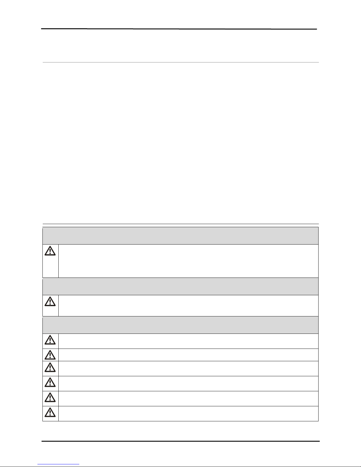
CAUTION: For safety reasons, this equipment must be operated and serviced by qualified personnel only.
WARNING: Servicing the unit, replacing or charging batteries, or using the com munications port must only
be done in an area known to be nonhazardous. Not for use in oxygen-enriched atmospheres.
WARNING: Power-off the monitor before servicing the unit or replacing the battery.
WARNING: Substitution of components may impair intrinsic safety and may cause an unsafe condition.
CAUTION: High off-scale readings may indicate explosive gas concentration(s).
CAUTION: Any rapid up-scale reading followed by a declining or erratic reading may indicate gas
concentration(s) beyond the upper scale lim it w hich may be haz ar dou s.
Silicone compound vapors or other known contaminants may affect the combustible gas sensor and cause
readings of combustible gas to be lower than actual gas concentrations. If the monitor has been used in an
►Copyright Notice
Ventis MX4™ and Ventis™ are trademarks of Industrial Scientific Corporation.
All trademarks and registered trademarks are the property of their respective owners.
These help materials or any part thereof may not, without the written consent of Industrial Scientific Corporation, be
copied, reprinted, or reproduced in any material form including but not limited to photocopying, transcribing,
transmitting, or storing it in any medium or translating it into any language, in any form or by any means, be it digitally,
electronic, mechanical, xerographic, optical, magnetic, or otherwise.
The information contained in this document is proprietary and confidential and all copyright, trademarks, trade names,
patents, and other intellectual pr operty rights in the documentation are the exclusive property of Industrial Scientific
Corporation unless otherwise specified. The information (including but not limited to data, drawings, specification,
documentation, software listings, source or object code) shall not at any time be disclosed directly or indirectly to any
third party without prior written consent.
The information contained herein is believed to be accurate and reliable. Industrial Scientific Corporation accepts no
responsibility for its use by any means or in any way whatsoever. Industrial Scientific Corporation shall not be liable
for any expenses, costs by damage that may result from the use of the information contained within this document.
Although every effort is made to ensure accuracy, the specifications of this product and the content herein are subject
to change without notice.
►Warnings and Cautionary Statements
General
Failure to perform certain procedures or note certain conditions may impair the performance of this
product. For maximum safety and optimal performance, please read and understand the Ventis MX4
Product Manual available online at the Ventis MX4 Resource Center at
Personnel
Read and understand the product manual completely before oper at ing or ser vici ng.
Hazardous Conditions, Poisons, and Contaminants
© 2018 Industrial Scientific Corporation
4
area where silicone vapors were present, always calibrate the monitor before next use to ensure accurate
measurements.
Oxygen-deficient atmospheres may cause combustible gas readings to be lower than actual concentrations.
Oxygen-enriched atmospheres may cause combustible gas readings to be higher than actual
concentrations.
Sudden changes in atmospheric pressure may cause temporary fluctuations in the oxygen reading.
Verify the calibration of the combustib le gas sensor af ter any i ncident where the combustible gas content has
caused the monitor to display an over-range con diti on.
Sensor openings, water barriers, and the pump inlet must be kept clean. Obstruction of the sensor openings
concentrations.
To avoid the potential of liquid being pulled into the sample tubing and pump assembly, it is recommended
aspirated monitor.
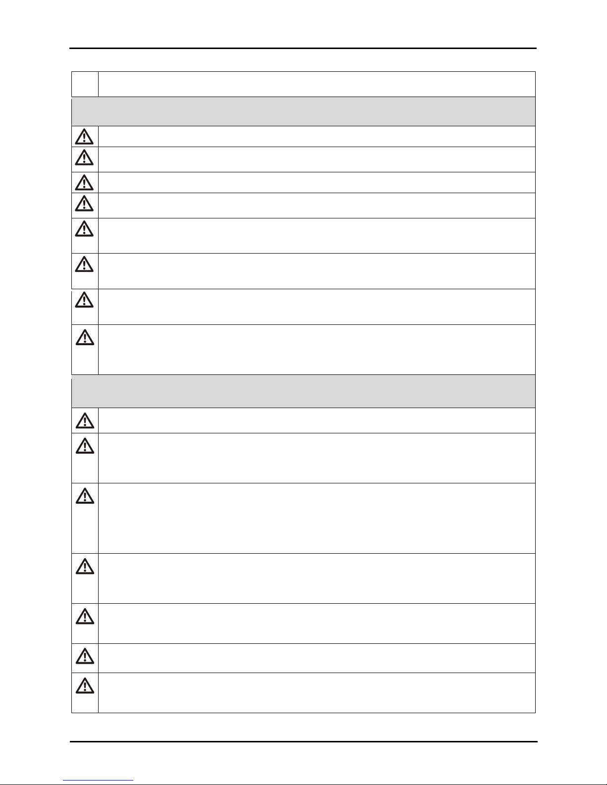
WARNING: INSERT THE ALKALINE BATTERIES WITH THE CORRECT POSITIVE “+” AND NEGATIVE “-“
EN92 and Duracell MN2400. Do NOT mix battery types.
WARNING: The use of leather cases can produce inaccurate readings with diffusion (non-a spira ted) gas
than O2, CO, CO2, H2S, and combustible gases (LEL/CH4).
Ensure all part-use restrictions (e.g., battery) meet any agency-mandated conditions of use.
Ensure all instrument-co nfigurable settings (e.g., always-on setting) meet any agency-mandated conditions
settings after docking.
The Ventis MX4 is CSA certified according to the Canadian Electrical Code for use in Class I, Division 1 and
range lithium-ion battery and has been calibrated to 50% LEL CH4.
CAUTION: CSA C22.2 No. 152 requires before each day’s usage, sensitivity must be tested on a k nown
zero/calibration section of the Product Manual.
The equipment complies with the standards IEC 60079-29-1 and EN 60079-29-1 for methane, propan e, and
be seven (7) hours rather than the eight (8) hours recommended by the standards, respectively.
MED-certified instruments may be used only when configured and maintained to dis all ow power-off when
the unit is in alarm.
The Mine Safety and Health Administration (MSHA) has approved the Ventis MX4 as a Permissible Multi-
General Usage
or pump inlet and/or contam ination of the water barriers may cause readings to be lower than actual gas
that Industrial Scientific filter (P/N 17027152) be used on the sample tubing when drawing samples using the
ORIENTATION. WARNING: The Ventis MX4 is only approved for use with AAA battery types Energizer
Ventis™ MX4 Product Manual
detection instruments for specific monitoring applications. Leather cases should be used ONLY as carrying
cases, and NOT for continuous monitoring, with diffusion instruments configured to measure gases other
Agency-issued Conditions of Use and Warnings
of use. When using instrument -com pati ble Indu str i al Scie ntific docking stations, maintain mandated settings
through the software (e.g., iNet Control or Accessory Software) or by manually configuring the instrument
Class I, Zone 1 Hazardous Locations within an ambient temperature range of T
has assessed only the %LEL combustible gas detection portion of this instrument for performance according
to CSA Standard C22.2 No. 152. This is applicable only when the monitor is use d in the diff usio n mode and
has been calibrated to 50% LEL CH
concentration of pentane or methane equivalent to 25% or 50% of full sc ale concentration. Accuracy must
, and when the monitor is used in the aspirated mode with an Extended
4
be within -0% to +20% of actual concentration. Accuracy may be corrected by referring to the
hexane with the following exception: as for the methane (mine) detector, the battery run time was verified to
: -20°C to +50°C. CSA
amb
Gas Monitor with the following warnings:
5 © 2018 Industrial Scientific Corporation

Ventis™ MX4 Product Manual
• MSHA approved for use with either the P/N 17134453-X2, 3.7 volt, Lithium-ion battery or P/N
determinations required by 30 CFR Part 75, subpart D.
SANS 1515-certified units may be used only as follows:
• With approved Lithium-ion batteries (see Ventis MX4 Accessories and Parts in this manual).
Industrial Scientific Corporation recommend s the moni tor be fully charged (when equipped with a
Monitors used infrequently should be fully charged every four months.
No part of the unit should be covered by any garment, part of a garment, or other item that would restrict the
flow of air to the sensors or impair the operator's access to the audible, visual, or vibration alarms.
Industrial Scientific Corporation recommends a full monitor calibration be performed monthly (at a minimum),
using a certified concentration(s) of Industrial Scientific calibration gas(es) to help ensure monitor accuracy.
Industrial Scientific Corporation recommends the monitor be zeroed and bump tested before each use with a
certified concentration(s) of Industrial Scientific calibration gas(es).
Battery contacts are exposed on batteries when they are removed from the monitor. Do not touch the battery
contacts and do not stack batteries on top of one another.
When reassembling the instrument or installing a battery pack, maintain ingress protection by tightening
key in this manual).
Contact your service representative immediately if you suspect that the Ventis MX4 is working abnormally.
17148313-2, 3.7 volt, lithium-ion Extended battery only. The battery pack is not user-replaceable. The
monitor battery and the lithium battery on the main PCB are technician replaceable only. Charge
rechargeable lithium-ion batteries with an ISC battery charger designed for use with this monitor in fresh
air locations only.
• The monitor is to be calibrated according to the procedures in the instruction manual only.
• The aspirated version of the Ventis MX4 is only approved for use with the Extended range battery only.
• The monitor must display methane in the percent-by-volume mode (0-5%) for compliance
• Diffusion applications
• Configured and maintained to disallow power -off when the unit is in alarm
• The Methane alarms are set as follows: low alarm = 1%vol and high alarm =1.4%vol
Recommended Practices
rechargeable battery), configured, and calibrated before first time use. If the lithium-ion battery is deeply
discharged, it can take up to an hour for the instrument display to indicate that the battery is charging.
each fastener to its stated torque value (see the “Ventis MX4 Monitor three-Dimensional Diagram” and its
►Ventis MX4 Resources
The Ventis MX4 Product Manual is the primary resource, within a full suite of learning tools, developed for the monitor
user. Its step-by-step “walk through” format covers everything from unpacking to set-up, operation, and service. All
Ventis MX4 users should read and understand the Product Manual prior to unpa ck ing or using the mon itor.
Ventis MX4 product-specific res ources are part of the organization’s broader training line-up, featuring online training
modules and face-to-face classroom programs for technicians, operators, first responders, trainers, and distributors.
Courses combine theory with hands-on learning, and can be tailored to the customer’s unique requirements and gas
monitoring applications.
The organization’s customer and technical support call centers provide product and order information, how-to product
assistance, and guidance for in-depth technical applications. Its service centers offer comprehensive factory repair
and maintenance services.
Industrial Scientific Corporation provides a full suite of resources to aid customers in the competent and safe use of
its products and services. With 19 manufacturing, support, and service centers and hundreds of distributors
worldwide, Industrial Scientific serves the globe’s gas detection needs.
© 2018 Industrial Scientific Corporation
6
Ventis™ MX4 Product Manual
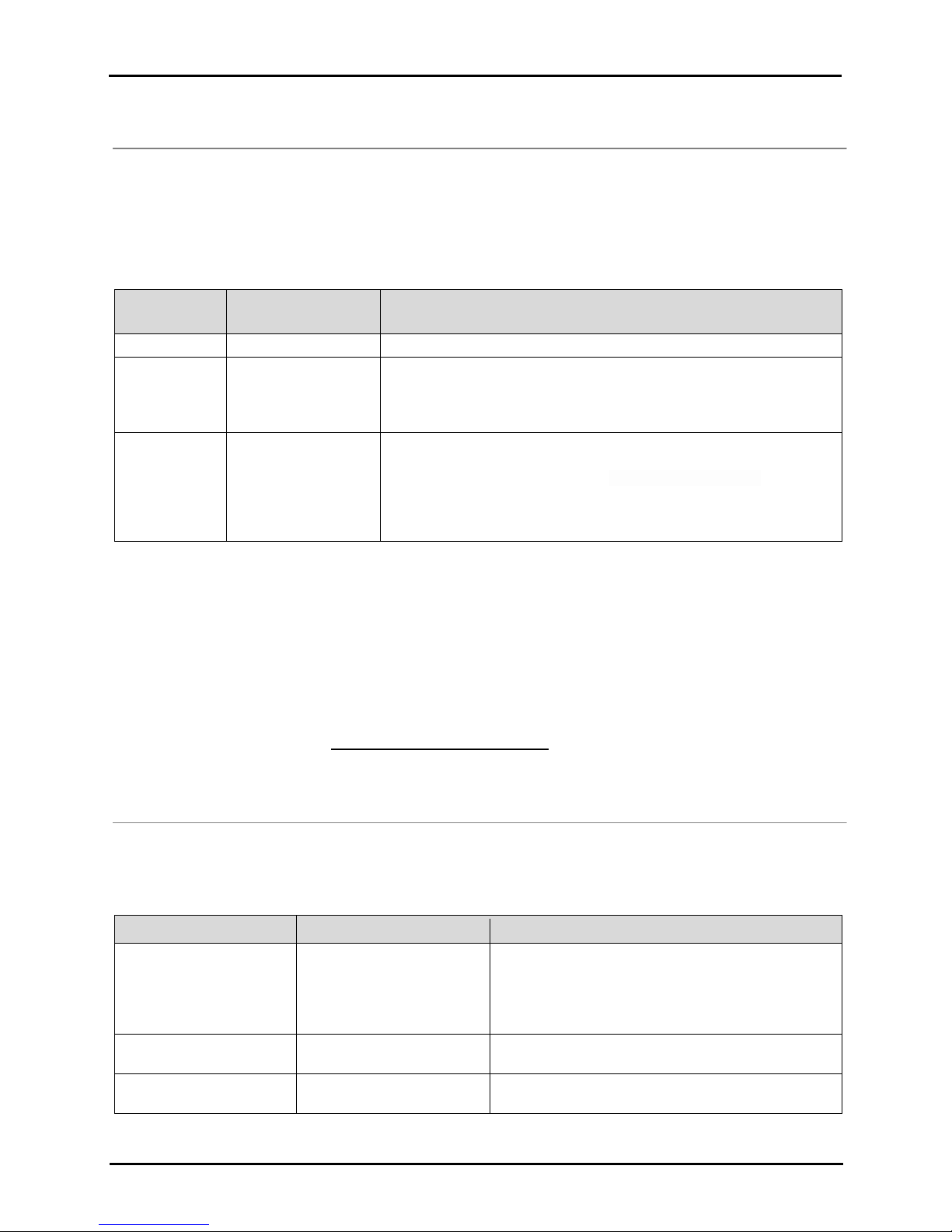
Sensor
Number available per
Gases Monitored
Oxygen
1
O2 (Oxygen) only
Combustible
1
Monitor can be configured for sen sor to measure ONE of the following:
• CH4 (0%-5%)
Toxic
2
Each sensor detects and measures only ONE of the following:
• SO2 (Sulfur Dioxide)
Quantity
Item
Notes
1 as ordered
Ventis MX4 Portable Multi-
The monitor type is indicated on the box label.
• Ventis MX4 Aspirated with Conversion Kit
1
Ventis MX4 Quick start guide
Review for important safety information before using
the monitor.
1 installed as ordered
Battery
One of four battery types are factory installed as
indicated on the box label.
►Ventis MX4 Capabilities
The Ventis MX4 is a portable multi-gas monitor. Offered as a diffusion monitor, it detects and measures gas(es)
present in open space. To enable monitor use within confined space locations, the Ventis MX4 is also offered as an
aspirated monitor. A pump module and batt ery accessor i es enable the conversion of either monitor for dedicated use
in either confined or open spaces.
Based on the customer’s monitor order, up to four sensors are factory installed enabling the monitor to continuously
and simultaneously detect and measure the presence of up to four specif ic gas es.
Category
Equipped with a multi-mode (audible, visual, and vibration) and multi-level alarm system, the Ventis MX4 monitor is
capable of notifying it s user of potentially hazardous gas concentrations.
The monitor performs continuous data logging at 10 second intervals. It can store approximately 90 days of data for a
four-sensor configuration. Its date- and time-stamped event log records and stores data for the following: 60 alarm
events, 30 error events, and 250 manually performed calibrations or bump tests. The memory, when full, overwrites
the oldest data as the newest readings and events are logged.
The Ventis MX4 monitor func tions as an independent device to monitor the environment for hazardous gas
concentrations. It is compatible with products that charge, calibrate, bump test, read and recor d inst rum ent data,
protect, and otherwise enable or enhance use of the monitor and its data. For a complete list of these products ,
please refer to the manual section, Ventis MX4 Accessories and Parts.
monitor
• LEL (Pentane)
• LEL (Methane)
• CO (Carbon Monoxide)
• CO/H2 Low (Carbon Monoxide with low H2 interference)
• H2S (Hydrogen Sulfide)
• NO
(Nitrogen Dioxide)
2
►Unpacking the Monitor
Contents
The monitor box contains the following items including, when ordered, those marked optional. Each item ordered
should be accounted for in the unpacking process.
gas Monitor
7 © 2018 Industrial Scientific Corporation
Options:
• Ventis MX4 Diffusion
• Ventis MX4 Aspirated

Ventis™ MX4 Product Manual
Quantity
Item
Notes
Options:
• Replaceable Alkaline
1 as ordered
Ventis Charger
Universal power cord. AC charger products includ e
interchangeable plugs (US, UK, EU, and AUS).
0 or 1
Calibration Cup
Diffusion – 1 included
Aspirated – 0 included
1
Calibration and Bump Test
Tubing
Diffusion – two feet of clear tubing
0 or 1
In-field Sampling Tubing
Diffusion – 0 included
Aspirated – Ten feet of black tubing
1
Final Inspection & Test
Contains the following factory set* information:
*Some factory set sensor values subject to user changes.
1
Warranty Card
--
• Rechargeable Lithium-ion (Li-ion)
• Rechargeable Slim extended lithium-ion (Li-ion)
• Rechargeable Extended range lithium-ion (Li-ion)
After unpacking, if any item is missing or appears to have been damaged, contact a local distributor of Industrial
Scientific products or Industrial Scientific Corporation (for con tact infor mation, please see the manual’s last page).
Monitor Overview
►
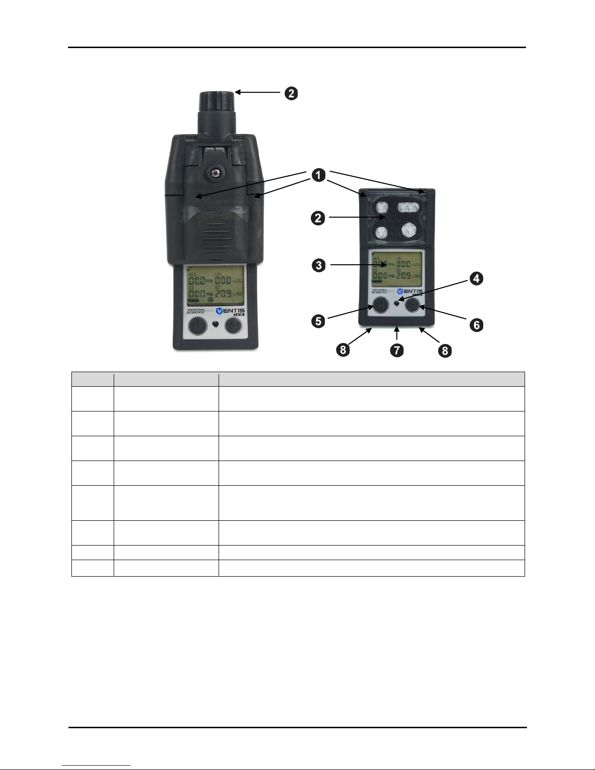
Hardware Features and Functions
The monitor’s case top (front of monitor) has two main sections. As shown below, the upper section contains the
sensor ports. The lower section houses the user interface features, a LCD display screen and two buttons. Each
feature’s general functions are noted below. As shown, the diffusion and aspirated monitors differ with respect to the
location of the air intake mechanism and visual alarm indicators.
The instrument may be used in any orientation when clipped to the user or when used with a compatible carrying
case. Normal instrument orientation for measuring gas concentration is hand held with sensors and display fac ing the
operator.
Report
• Monitor Set-up Date
• Monitor Part Number (P/N)
• Monitor Serial Number (S/N)
• For Each Sensor*:
• P/N
• S/N
• Type
• Location
• Alarm level values
• Span gas values
• Span reserve values
© 2018 Industrial Scientific Corporation
8
Ventis™ MX4 Product Manual
Number
Feature
Functions
1
Visual alarm indicator
Signals an alarm or warning; frequency varies by alarm level. Also used as a
confidence indicator.
2
Pump inlet (aspirated)
Sensor ports (diffusion)
Air intake; calibration and bump test gas intake.
3
LCD display
User interface; backlight flashes when monitor is in system, high, or low
alarm states.
4
Audible alarm ports
On when monitor is in system, high, or low alarm states; frequency and tone
vary by alarm level. Also used for warnings and as confidence indicator.
5
On/Off/Mode button
Used to power-on and power-off. Also used to bypass a process/step or
Sets values in configuration mode.
6
Enter button
Used to begin a process/s tep in a process. Edits values in configuration
mode.
7
IrDA interface
Indicates infrared light data exchange in-progress.
8
Charging contacts
Battery charging.
advance to a next screen in both gas monitoring and configuration modes.
Display Screen
The Ventis MX4 Boot-up Screen, as shown below, serves to introduce all icons and the alpha-numeric items (e.g.,
8.8.8) that can appear on the display when the monitor is in use, docked, or charging. Each display item is stationary,
communicates unique information, and appears only when relevant to the task being performed.
A sample Gas Monitoring Screen is also shown below, next to the boot-up screen. This illustrates how the icons and
the alpha-numeric characters work together to c ommunicate several points of information to the monitor user.
9 © 2018 Industrial Scientific Corporation

Ventis™ MX4 Product Manual
diffusion monitor, the pump icon does not appear on the display.
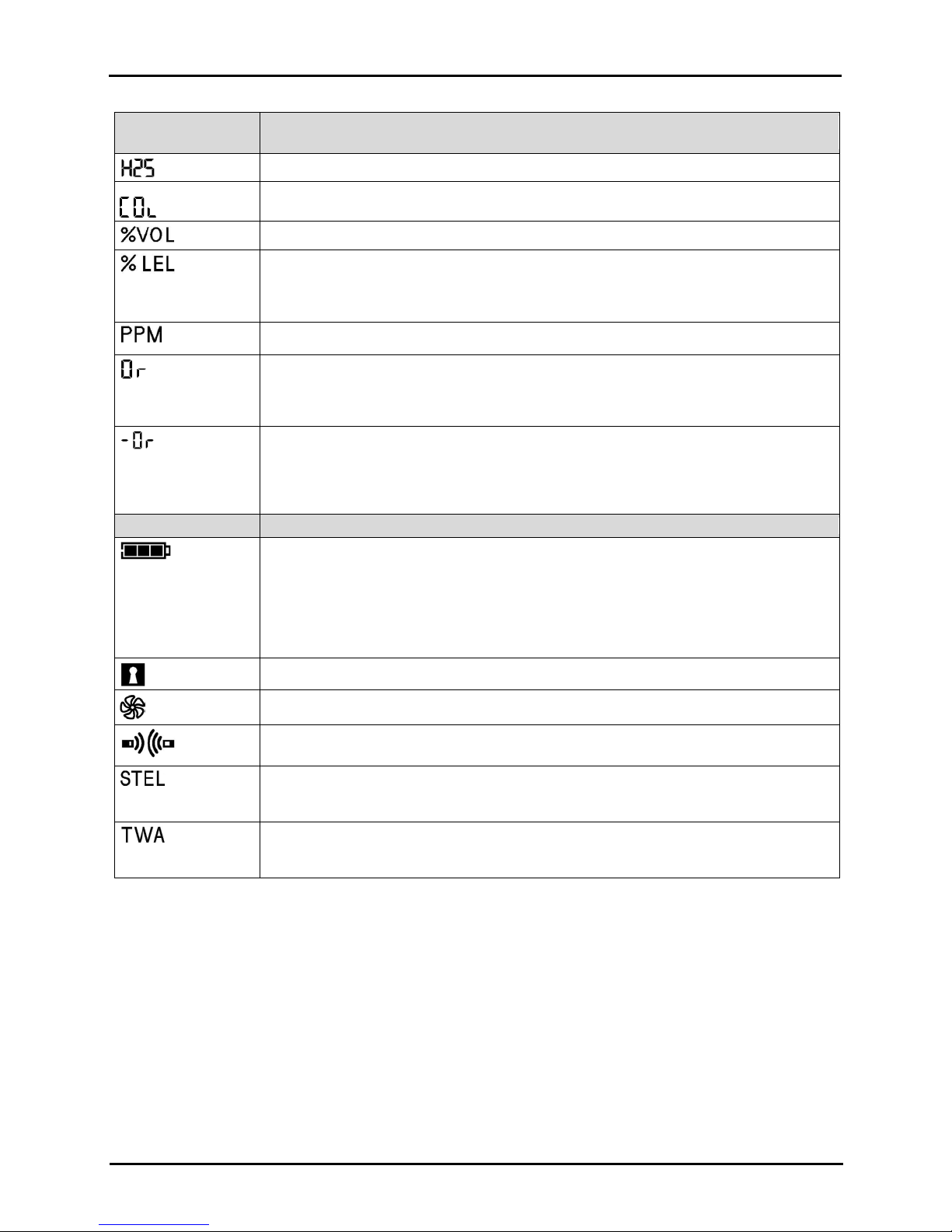
Top Row Icons
Definition
Status: indicates no monitor or sensor faults.
Warning: indicates monitor or sensor fault.
Zero: communicates zero status (e.g., zero results, zero in-progress, etc.).
Gas Cylinder: communicates calibration related information (calibration due, calibration
Clock: indicates a process is in-progress.
Calendar: communicates overdue warnings for service items (calibration, bump testing,
etc.).
Alarm: indicates an alarm causing condition.
Low level audio alarm is on.
High level audio alarm is on.
Peak: displayed when peak detection values are viewed.
Alpha-numeric
display values
Definition
Carbon Monoxide (CO)
Methane (CH4)
Sulfur Dioxide (SO2)
Lower Explosive Limit. Display variations:
“UEG” (German)
Oxygen (O2)
Nitrogen Dioxide (NO2)
Boot-Up Screen
All possible screen images.
Gas Monitoring Screen
Sample screen in gas monitoring mode.
NOTE: Display screens featured throughout this manual include the “pump” icon.
Similar in appearance to a fan, it indicates an aspirated monitor is in use. For a
It is helpful to view the boot-up screen in sections. The top and bottom rows each contain icons. The main function of
the middle section, in gas monitoring mode, is to communicate gas concentration readings. Definitions for all icons,
gas name abbreviations, gas measurement unit s, and oth er indi cators are provided below. Where appl ic able , disp lay
variations are noted.
apply gas, etc.).
“LEL” (English)
“LIE” (French)
© 2018 Industrial Scientific Corporation
10
Ventis™ MX4 Product Manual
Alpha-numeric
display values
Definition
Hydrogen Sulfide (H2S)
CO H2/Low
Percentage Volume: O
and CH4 measurement unit
Percentage unit for combustible gases; display variations:
“% UEG” (German)
Parts Per Million: H2S, CO, SO2 and NO2 measurement unit.
Over-range: for any sensor in over-range, indicates the measured gas concentration is
“Sup” (French)
Negative Over-range: for any sensor in negative over-range indicates the measured gas
“InF” (French)
Bottom Row Icons
Definition
Battery level indicator; display v ariations:
3 black bars = 67% – 100% charge remaining
Security Code: indicates code is set or to be entered.
Pump: shown anytime an aspirated monitor is in use.
Indicates IrDA communication is in-progress.
Short Term Exposure Limit: communicates STEL values. Display variations:
“VLE” (French)
Time Weighted Average: communicates TWA values. Display variations:
“VME” (French)
2
“% LEL” (English)
“% LIE” (French)
greater than the measurement range of the sens or. Display variations:
“Or” (English and German)
concentration is less than the negative measurement range of the sensor. Display
variations:
“-Or” (English and German)
Empty battery icon with three dashes in place of each sensor reading = critical battery
warning
Flashing empty battery icon = low battery warning
1 black bar = < 33% charge remaining
2 black bars = 34% – 66% charge remaining
“STEL” ( English and German)
“TWA” (English and German)
Alarms
NOTICE
→ All monitor alarms and warnings should be taken seriously and responded to as stated in company safety
standards.
→ Once initiated, an alarm will remain on while the alarm condition is present. For gas-related alarms, once the
detected gas concentration changes, the alarm indicators will change to reflect any new condition such as
low-alarm gas, high-alarm gas, over-range gas, or no gas alarm.
→ When the latch alarm feature is enabled and the monitor goes into alarm, it will remain in alarm until the
alarm condition no longer exists and the monitor user presses the ENTER button for one second. This
applies only to gas-related alarms.
11 © 2018 Industrial Scientific Corporation
Ventis™ MX4 Product Manual
Display
Description
condition, the alarm indi cators will turn on.
alarm icon displays.
A negative over-range condition occurs when
and the up arrow icon displays.
A high alarm condition occurs when the
A low alarm condition occurs when the
It is practical for the monitor user to be aware of the possible alarms prior to monitor set-up and use. The Ventis MX4
has four alarm and warning levels. A “system level” alarm generates the highest frequency tone and highest level
visual and vibration signals. It is used to indicate such events as a p ump, critical battery failure, or sensor failure. The
“high” or “low” level audio alarms, in combination with visual and vibration indicators, turn on when gas concentration
readings are over-range, high, or low. The lowest level indicator is a warning with beep patterns to indicate service
needs (e.g., low battery or calibration due). The beep is also used as a confidence indicator w hen enabled.
Alarm types and their alarm generating conditions are described below.
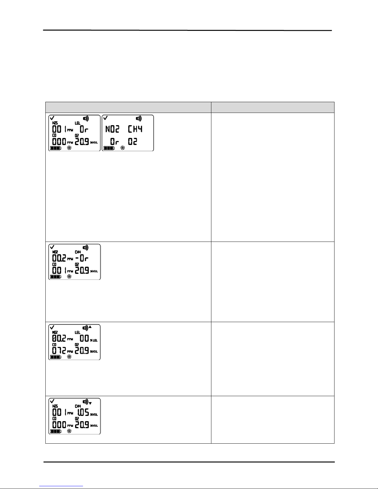
An over-range condition occurs when the gas
concentration value sensed is above the
sensor’s measuring range.
Over-range Alarm Screen
The “Or” message indicates which sensor(s) is reading an over-
range condition(s). All other sensors show their current gas
concentration readings on a numeric display (left) or gas names
on a text display (right). The high level alarms turn on and the
alarm icon displays.
After any over-range alarm , the monitor should
be calibrated.
NOTES: The O
and toxic sensor values
2
normally reset when the gas sensed reaches an
acceptable range.
If the LEL reads over-range, the alarm latches
and the LEL sensor is automatically turned off.
Press the enter button to turn on the LEL
sensor. This will turn off the alarm indicators .
After a warm-up period of approximately 30
seconds, an LEL reading will display. If the new
reading is an over-range or other alarm
Negative Over-range Alarm Screen
The “-Or” message indicates which sensor is reading a negative
over-range condition. All other sen sors displ ay their current gas
concentration readings*. The high level alar ms turn on and the
High Alarm Screen
A flashing gas concentration value* indicates which sensor(s)
reading(s) is the cause for alarm. The high level alarms turn on
the gas concentration value sensed is less than
the sensor’s measuring range.
After any negative over-range alarm, the
monitor should be calibrated.
concentration of gas sensed reaches a level
greater than the monitor’s high alarm value
setting for a sensor(s).
concentration of gas sensed reaches the
monitor’s low alarm value setting for a
sensor(s).
© 2018 Industrial Scientific Corporation
12
Display
Description
Low Alarm Screen
and the down arrow icon dis plays.
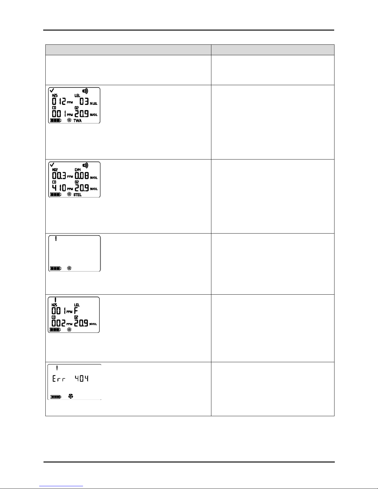
and the TWA icon flashes.
A TWA alarm occurs when the calculated time
and the STEL icon flashes.
The STEL alarm occurs when the short term
The system level alarms turn on and the error icon displays.
Alarm occurs when the monitor registers no
audio alarm turns on and the error icon displays.
Alarm occurs when any ins talled sensor’s data-
Critical Error Screen
Error codes 4XX to 5XX (404 shown here)
A flashing gas concentration value* indicates which sensor(s)
reading(s) is the cause for alarm. The low level alarms tur n o n
Ventis™ MX4 Product Manual
weighted average reaches the monitor’s
hazardous value for the set time frame.
TWA Alarm Screen
A flashing gas concentration value* indicates which sensor(s)
reading(s) is the cause for alarm. The low level alarms tur n o n
STEL Alarm Screen
A flashing gas concentration value* indicates which sensor(s)
reading(s) is the cause for alarm. The low level alarms turn on
No Sensor Installed Screen
exposure value exceeds the acceptable limit.
sensors installed.
Sensor Data Fail Screen
A flashing “F” indicates which sensor is the cause for alarm. The
13 © 2018 Industrial Scientific Corporation
related operations fail and the sensor is not
operational.
indicate the monitor has detected a malfunction.
The unit is not operational and and should be
examined by a qualified technician or reported
to Industrial Scientific for service or repair
information.
Ventis™ MX4 Product Manual
Display
Description
the flow is less than 200 cc/m +0, -25%.
flashes.
alarm sounds for 10 minutes before powering off the monitor.
This alarm occurs when there is not enough
display.
Alarm occurs when one or more sensors are
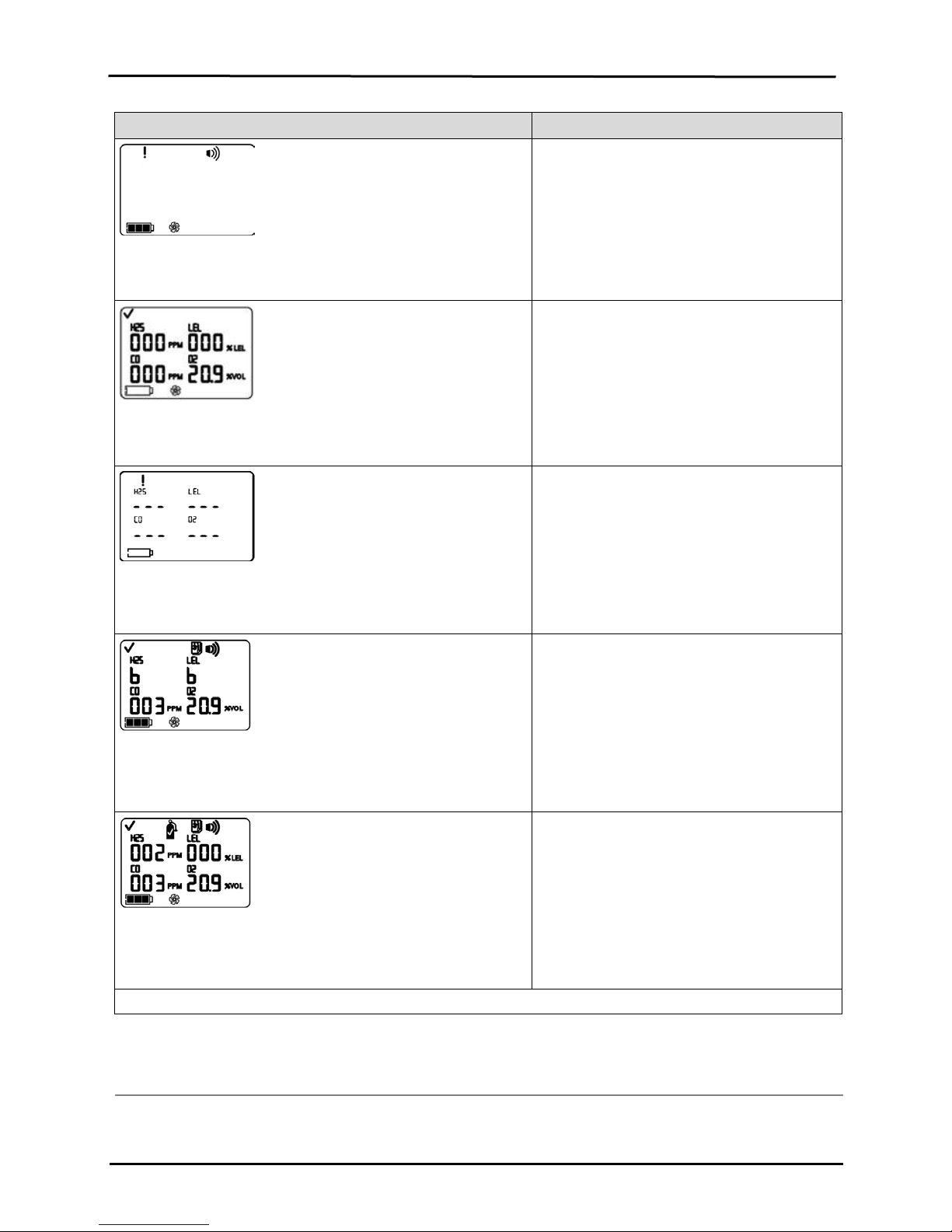
alarm icons display. The gas cylinder icon flashes.
Alarm occurs when one or more sensors are
* The numeric mode display shows gas concentration values; the text mode display shows gas type names in place of gas values.
Pump Fault Alarm
The system level alarms turn on and the error icon displays.
Alarm occurs when, if attached, the pump is not
operating correctly. While in alarm, every ten
seconds the monitor attempts to restart the
pump. If unsuccessful, the monitor remains in
alarm.
Note: The nominal flow rate is >200 cc/m (.2
LPM). A pump fault alarm will occur when
Alarm occurs when the monitor’s battery
reaches a low level of charge or is near ing its
end of life.
Low Battery Warning Screen
A beep sounds every 60 seconds and the empty battery icon
Critical Battery Alarm
The empty battery icon indicates a battery life warning, while
three dashes display in plac e of each sensor reading. The high
Bump Overdue Screen
A “b” indicates which sensor(s) is overdue for bump testing. Two
beeps sound every 30 seconds and the calendar and alarm icons
battery life remaining for continued operation.
The battery must be char ged or replaced.
The instrument is NOT detecting gas at this
time.
due for a bump test. If the monitor settings
permit, an in-field bump test may be performed
in an area known to be nonhazardous.
due for calibration. If the monitor settings
permit, an in-field calibration can be performed
in an area known to be nonhazardous.
Calibration Due Alarm Screen
The gas value flashes for each sensor overdue for calibration.
Three beeps sound every 30 seconds and the calendar and
►Monitor Set-up
© 2018 Industrial Scientific Corporation
14

Ventis™ MX4 Product Manual
Battery Compatibility
Rechargeable
(part number*)
Replaceable
(part number*)
Ventis MX4 diffusio
Ventis MX4
*X indicates color and Y indicates approvals.
Cover
Cover
Preparing the monitor for first time use is a “3-C” process: charge (if equipped with a lithium-ion battery), configure,
and calibrate. This manual sec tion cov ers c harging and configuration for set-up purposes and can be consulted for
ongoing instruction thereafter. Immediately following this section, calibration is covered in the manual section, Use
and Service.
Batteries
As shown below, the Lithium-ion and Slim extended lithium-ion batteries are compatible with the diffusion instrument
only. The Extended range battery can be installed for use with a diffusion or aspirated instrument. The battery's
orderable part numbers are supplied in Battery part num bers and optio ns.
Lithium-ion battery Slim extended
lithium-ion battery
(VTSB-1XY*) (VTSB-4XY*) (VTSB-2XY*) (VTSB-3XY*)
n
aspirated
Yes Yes Yes Yes
No No Yes (without cover) Yes (without cover)
Extended range
lithium-ion battery
Alkaline battery
Docking Stations, Chargers, and other Accessories
Fully charge the monitor before first use. The lithium-ion equipped Ventis MX4 can be charged using any of the
products listed below.
Part Number Product
Docking Stations
18109327 DSX™ Docking Station for Ventis
Calibration Stations
18108631 V-Cal™ Calibration Station
18107664 V-Cal™ 6-Unit Calibration Station
Chargers
18108191
18108209
18108650 Ventis 6-Unit Charger
18108651 Ventis Single Unit Automotive Charger, 12 VDC
18108652 Ventis Single Unit Truck-Mount Charger, 12 VDC, with Cigarette Adapter
15 © 2018 Industrial Scientific Corporation
Ventis Single Unit Charger
Ventis Single Unit Charger / Datalink
Ventis™ MX4 Product Manual
Forward insert position
Once the insert is placed
position.
Insert side 1: forward
Insert side 2: forward
Insert side 1: Rear
Part Number Product
18108653 Ventis Single Unit Truck-Mount Charger, 12 VDC, Hard Wired
NOTE: The above products are all equipped with a yellow LED “presence” indicator. This LED confirms that the monitor is properly seate d in the
cradle such that the monitor can cha rge; however, it is NOT intended to be used as a charging indicator. This LED indicator may go out intermittently
during normal charging functions and will not light if the unit is fully charged when placed in the cradle. Always refer to the monitor display’s battery
level indicator to confirm the battery charge level.
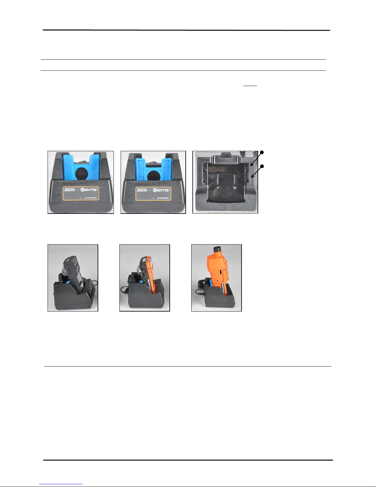
Battery Charging
Charger insert placement
If the charger includes an insert, adjust the insert’s position to ensure the battery contacts touch the charging
contacts.
Rear insert position
—
Lithium-ion battery Slim extended lithium-ion
battery
Extended range lithiumion battery
into the desired position, a
firm push down will secure
it in place.
position
position
position
To prevent losing the
insert, keep it in the cradle
in the most often used
NOTE: Do NOT touch the battery contacts located at the front of the charger as contaminants and damage will inhibit the
battery’s ability to charge.
Power-on and -off
To power-on the Ventis MX4, press ON/OFF/MODE and hold for three to five seconds. During the first ten to15
seconds the monitor is on, its firmware completes internal tests and the us er sees or hears what is described and
shown below. Following this initialization phase, a countdown screen displays. During this 20-second countdown, the
monitor user can enter configuration mode to manually adjust monitor settings.
© 2018 Industrial Scientific Corporation
16
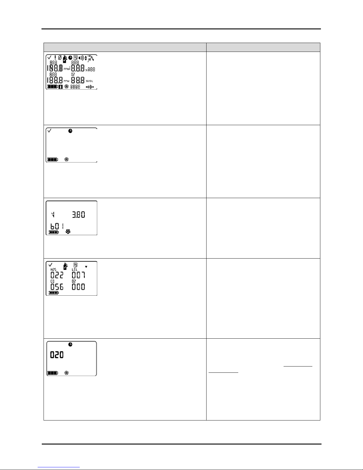
Display and Options
Instructions
briefly, then off.
started and, if needed, adjusted for optimum flow.
The Software Version Screen message displays for five seconds.
Enter configuration mode
Visual Test Screen
Displays for up to five seconds as the monitor completes a sensor
and alarm check. Visual, vibration, and audio alarms turn on
Pump Set-up Screen
Displays for five to seven seconds for an aspirated monitor. The
monitor checks for the presence of a pump. If present, the pump is
Ventis™ MX4 Product Manual
No user action required.
Be sure the pump inlet is not blocked.
Software Version Screen
Calibration Days Screen
When the up arrow (▲) is featured, the number of days displayed
for each sensor indicates when the next calibration is due. When
the down arrow (▼) is featured, the number of days displayed
indicates when the last calibration occurred.
Countdown Screen
Displays the 20 second countdown, one second at a time, from 20
to one. Options :
Enter gas monitoring mode
No user action required.
No user action required.
To enter gas monitoring mode:
allow the countdown to complete and
advance to the Gas Moni toring Screen.
Proceed to the manual section, Monitor Use
and Service.
To enter configuration mode:
simultaneously press ON/OFF/MODE and
ENTER, hold for three seconds, and release.
17 © 2018 Industrial Scientific Corporation
 Loading...