

Industrial Scientific Ventis LS Product Manual
Ventis LS
Multi-gas Monitor
Product Manual
Set-up
Operation
Service
17153965-1
Edition 2
Aug. 24, 2018
Multilingual
user documentation resources
available at
www.indsci.com/VentisLSresources
Chinese
French
German
Spanish
and more!
(Revision 2)

Ventis LS Product Manual
Table Of Contents
Copyright Notice .......................................................................................................................................................... 3
Warnings and Cautionary Statements ....................................................................................................................... 3
General ...................................................................................................................................................................... 3
Personnel ................................................................................................................................................................... 3
Hazardous Conditions, Poisons, and Contaminants .................................................................................................. 3
Factors that Affect Monitor Performance .................................................................................................................... 4
Certifications .............................................................................................................................................................. 4
Recommended Practices ........................................................................................................................................... 5
Ventis LS Resources ................................................................................................................................................... 6
Ventis LS Capabilities .................................................................................................................................................. 6
Unpacking the Monitor ................................................................................................................................................ 7
Contents ..................................................................................................................................................................... 7
Reporting a Problem .................................................................................................................................................. 7
Monitor Overview ......................................................................................................................................................... 8
Hardware Features and Functions ............................................................................................................................. 8
Display Screen ........................................................................................................................................................... 9
Alarms ...................................................................................................................................................................... 11
Monitor Set-up ............................................................................................................................................................ 13
Battery Properties .................................................................................................................................................... 14
Charging the Lithium-ion Battery Packs ................................................................................................................... 14
Power-On and -Off ................................................................................................................................................... 15
Configuration ............................................................................................................................................................ 16
Introduction .......................................................................................................................................................... 16
Instructions ........................................................................................................................................................... 16
Monitor Use and Service ........................................................................................................................................... 23
Zero, Calibration, and Bump Testing ........................................................................................................................ 23
Introduction .......................................................................................................................................................... 23
Prepare the gas cylinder for use .......................................................................................................................... 25
Zero and Quick Calibration Process ................................................................................................................. 26
Quick Bump Test Process ................................................................................................................................ 29
Recommended Practices for In-field Air Sampling ................................................................................................... 31
Cleaning ................................................................................................................................................................... 31
Service ..................................................................................................................................................................... 31
Battery Packs ................................................................................................................................................... 31
Sensor, Sensor Barrier, LCD, and Vibrating Motor Replacement .................................................................... 32
Specifications and Certifications .............................................................................................................................. 35
Monitor Specifications .............................................................................................................................................. 35
Sensor Specifications ............................................................................................................................................... 35
Certifications ............................................................................................................................................................ 36
Wireless certification ................................................................................................................................................ 36
Warranty ..................................................................................................................................................................... 36
Limitation of Liability ................................................................................................................................................. 36
2 © Industrial Scientific Corporation
Ventis LS Product Manual
General
IMPORTANT
www.indsci.com/ VentisLSresources.
Personnel
CAUTION: For safety reasons, this equipment must be operated and serviced by qualified personnel only.
d'entretenir ou de réparer l'équipement.
Hazardous Conditions, Poisons, and Contaminants
WARNING: Servicing the unit, replacing or charging battery pack s, or using the co mmu ni cat ions port must only
be done in an area known to be nonhazardous. Not for use in oxygen-enriched atmospheres.
WARNING: Power-off the monitor before servicing the unit or replacing the battery.
WARNING: Substitution of components may impair intrinsic safety and may cause an unsafe condition.
AVERTISSEMENT: La substitution de composants peut compomettre la securite intrinseque.
CAUTION: High off-scale readings may indicate explosive gas concentration(s).
CAUTION: Any rapid up-scale reading followed by a declining or erratic reading may indicate gas
concentration(s) beyond the upper scale lim it w hich may be haz ar dou s.
Silicone compound vapors or other known contaminants may affect the combustible gas sensor and cause
measurements.
Copyright Notice
Ventis™ is a trademark of Industrial Scientific Corporation.
All trademarks and registered trademarks are the property of their respective owners.
These help materials or any part thereof may not, without the written consent of Industrial Scientific Corporation, be
copied, reprinted, or reproduced in any material form including but not limited to photocopying, transcribing,
transmitting, or storing it in any medium or translating it into any language, in any form or by any means, be it digitally,
electronic, mechanical, xerographic, optical, magnetic, or otherwise.
The information contained in this document is proprietary and confidential and all copyright, trademarks, trade names,
patents, and other intellectual pr operty rights in the documentation are the exclusive property of Industrial Scientific
Corporation unless otherwise specified. The information (including but not limited to data, drawings, specification,
documentation, software listings, source or object code) shall not at any time be disclosed directly or indirectly to any
third party without prior written consent.
The information contained herein is believed to be accurate and reliable. Industrial Scientific Corporation accepts no
responsibility for its use by any means or in any way whatsoever. Industrial Scientific Corporation shall not be liable
for any expenses, costs by damage that may result from the use of the information contained within this document.
Although every effort is made to ensure accuracy, the specifications of this product and the content herein are subject
to change without notice.
Warnings and Cautionary Statements
Failure to perform certain procedures or note certain conditions may impair the performance of this
product. For maximum safety and optimal performance, please read and understand the Ventis LS
Product Manual available online at the Ventis LS Resource Center at
Read and understand the product manual completely before oper at ing or ser vici ng.
ATTENTION: Pour des raisons de sécurité, cet équipment doit étre utilesé entretenu et réparé uniquement par
un personnel qualifié. Étudier le manuel d'instructions en entier avant d'utiliser,
ATTENTION: Des lectrures supérieures a l'échelle peuvent indiquer des concentrations explosives.
readings of combustible gas to be lower than actual gas concentrations. If the monitor has been used in an
area where silicone vapors were present, always calibrate the monitor before next use to ensure accurate
© Industrial Scientific Corporation
3
Ventis LS Product Manual
Factors that Affect Monitor Performance
Oxygen-deficient atmospheres may cause combustible gas readings to be lower than actual concentrations.
Oxygen-enriched atmosphere s may cau se combu stib le gas readings to be higher than actual concentratio ns.
Sudden changes in atmospheric pressure may cause temporary fluctuations in the oxygen reading.
Verify the calibration of the combustible gas sensor after any incident where the combustible gas content has
caused the monitor to display an over-range con diti on.
Sensor openings and water barriers must be kept clean. Obstruction of the sensor openings and/or
contamination of the water barriers may cause readings to be lower than actual gas concentrations.
Do not use the ISC Alkaline battery pack (P/N:17150608) with the Ventis LS monitor.
The Ventis LS is CSA certified according to the Canadian Electrical Code for use in Class I, Division 1 and
CSA Standard C22.2 No. 152. This is applicable only when the monitor has been calibrated to 50% LEL CH
4.
CAUTION: CSA C22.2 No. 152 requires before each day’s usage, sensitivity must be tested on a known
section of the Product Manual.
Certifications
The EC type examination certificate is DEMKO 11 ATEX 1104473 with marking code Ex d ia I Mb/Ex d ia IIC
T4 Gb for equipment category II 2G and I M2.
The IECEx examination certificate is IEC Ex UL11.0023 with marking code Ex d ia IIC T4 Gb.
The model Ventis LS complies with relevant provisions of European ATEX directive 94/9/EC and EMC
directive 2004/108/EC
The Ventis LS Multi-gas monitor is constructed with reference to published standards of directive 2006/95/EC,
These detectors have been investigated for risk of explosion, fire, and electric shock only. They have not been
investigated for performance relative to their ability to detect gases or vapors.
The radio in the Industrial Scientific Ventis LS Portable Multi Gas monitor has been assessed to and found to
This equipment has been tested and found to comply with the limits for a Class A digital device, pursuant to
authority to operate the equipment.
Class I, Zone 1 Hazardous Locations within an ambient temperature range of T
: -20°C to +50°C. CSA has
amb
assessed only the %LEL combustible gas detection portion of this instrument for performance according to
concentration of pentane or methane equivalent to 25% or 50% of full scale concentration. Accuracy must be
within -0% to +20% of actual concentration. Accuracy may be corrected by referring to the zero/calibration
to eliminate electrical risks and fulfill 1.2.7 of ANNEX II of directive 94/9/EC.
be below limits as defined in FCC; Innovation, Science and Economic Development Canada; and European
Council recommendation 1995/519/EC requirements for human exposure to electromagnetic fields.
Part 15 B and C of the FCC Rules. These limits are designed to provide reasonable protection against harmful
interference when the equipment is operated in a commercial environment. This equipment generates, uses,
and can radiate radio frequency energy and, if not installed and used in accordance with the instruction
manual, may cause harmful interference to radio communications. Operation of this equipment in a residential
area is likely to cause harmful interference in which case the user will be required to correct the interference at
their expense.
• The instrument complies with part 15 of the FCC Rules. Operation is subject to the following two
conditions:
• This device must accept any interference received, including interference that may cause undesired
operation.
Changes or modification made that are not expressly approved by the manufacturer could v oid the user’s
4 © Industrial Scientific Corporation
Ventis LS Product Manual
This device complies with Industry Canada license-exempt RSS standard(s). Operation is subject to the
The Ventis LS Portable Multi Gas Monitor contains 1 radio communication module that generates radio
Wifi Radio
Maximum Radiated Transmit Power
2405 to 2480 MHz
8.2 dBm (6.6 mW)
Recommended Practices
Industrial Scientific recommends persons with a pacemaker or implantable cardio defibrillator (ICD) should
recommendations.
Industrial Scientific Corporation recommends the monitor be charged, configured, and calibrated b efor e fir st
time use.
Industrial Scientific Corporation recommends a full monitor calibration be performed monthly (at a minimum),
using a certified concentration(s) of Industrial Scientific calibration gas(es) to help ensure monitor accuracy.
Industrial Scientific Corporation recommends the monitor be zeroed and bump tested before each use with a
certified concentration(s) of Industrial Scientific calibration gas(es).
Battery contacts are exposed on battery packs when they are removed from the monitor. Do not touch the
battery contacts and do not stack battery packs on top of one another.
Contact your service representative immediately if you suspect that the Ventis LS is working abnormally.
following two conditions: (1) this device may not cause interference, and (2) this device must accept any
interference, including inter fer ence that may cause unde sired operation of the device.
Le présent appareil est conforme aux CNR d'Industrie Canada applicables aux appareils radio exempts de
licence. L'exploitation est autorisée aux deux conditions suivantes : (1) l'appareil ne doit pas produire de
brouillage, et (2) l'utilisateur de l'appareil doit accepter tout brouillage radioélectrique subi, même si le
brouillage est susceptible d'en com prom ettr e le fon ctio nne me nt .
frequency energy. They frequency and output power are listed below:
maintain a minimum separation distance of 15 cm (6 ") between the pacemaker or ICD and a wireless-enabled
instrument. Please consult your physician or pacemaker or ICD manufacturer for additional guidance and
© Industrial Scientific Corporation
5
Ventis LS Product Manual
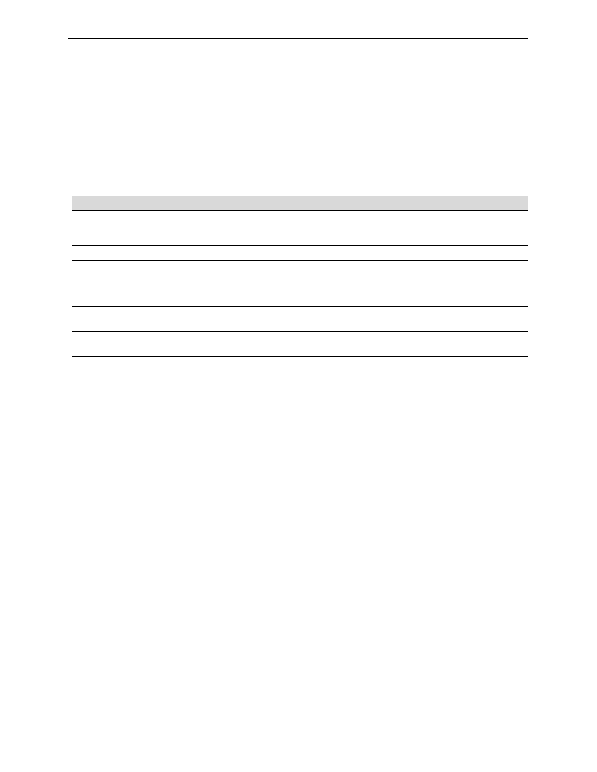
Sensor
Category
Number available
per monitor
Gases Monitored
Oxygen
1
O2 (Oxygen) only
Combustible
1
Monitor can be configured for sensor to measure ONE of the following:
• CH4 (0%-5%)
Toxic
2
Each sensor detects and measures only ONE of the following:
• SO2 (Sulfur Dioxide)
Ventis LS Resources
The Ventis LS Product Manual is the primary resource, within a full suite of learning tools, developed for the monitor
user. Its step-by-step “walk through” format covers everything from unpacking to set-up, operation, and service. All
Ventis LS users should read and understand the Product Manual prior to unpacking or using the monitor.
A companion to the manual, the Ventis LS Reference Guide ships with the monitor. It serves to announce all warnings
and cautionary statement s relev ant to gener al mon itor use . The guide also features process charts that provide an
overview of four fundamental tasks: operation/start-up, configuration, calibration, and functional “bump” testing. These
charts are tools for the user who is both familiar with the manual and proficient in the performance of the given t as k.
A collection of audio-visual learning tools is also available online at the Ventis LS Resource Center. Here the user can
watch fully narrated step-by-step demonstrations of instruction sets outlined in the manual. These training modules
allow the user to view the full presentation of a process, such as calibration, or to access a particular segment within
that process. These Ventis LS product-specific resources are part of the organization’s broader training line-up,
featuring face-to-face classroom programs for technicians, operators, first responders, trainers, and distributors.
Courses combine theory with hands-on learning, and can be tailored to the customer’s unique requirements and gas
monitoring applications.
The organization’s customer and technical support call centers provide product and order information, how-to product
assistance, and guidance for in-depth technical applications. Its service centers offer comprehensive factory repair
and maintenance services.
Industrial Scientific Corporation provides a full suite of resources to aid customers in the competent and safe use of
its products and service s. With manufac turing, support, and service centers and hundr ed s of distrib ut ors w orldwide,
Industrial Scientific serves the globe’s gas detection needs.
Ventis LS Capabilities
The Ventis LS is a portable multi-gas monitor. It detects and measures gas(es) present in open space. Its wireless
feature continuously communicates gas readings and alarm events to a control center. Based on the customer’s
monitor order, up to four sensors are factory installed enabling the monitor to continuously and simultaneously detect
and measure the presence of up to four specific gases.
• LEL (Pentane)
• LEL (Methane)
• CO (Carbon Monoxide)
S (Hydrogen Sulfide)
• H
2
• NO
Equipped with a multi-mode (audible, visual, and vibration) and multi-level alarm system, the Ventis LS monitor is
capable of notifying it s user of potentially hazardous gas concentr atio ns. It is also equipped with motion alarms and a
panic alarm.
The monitor performs continu o us datalogging at 10 second intervals. It can store approximately 90 days of data for a
four-sensor configuration. Its date- and time-stamped event log records and stores data for 24 alarm events and a
minimum of 15 error events. The memory, when full, overwrites the oldest data as the newest readings and events
are logged.
(Nitrogen Dioxide)
2
6 © Industrial Scientific Corporation
Ventis LS Product Manual
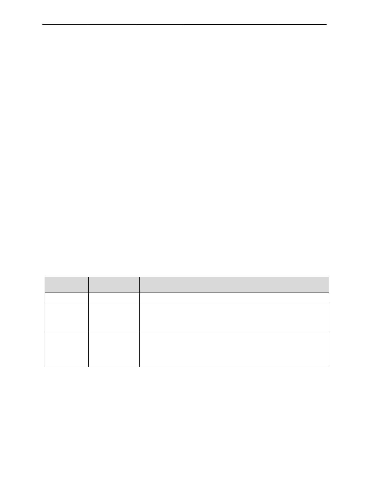
Quantity
Item
Notes
1 as ordered
Ventis LS Portable Multi-gas
-1
Ventis LS Reference Guide
A companion to the Ventis LS Product Manual.
1 installed as ordered
Battery Pack
One of two battery types is factory installed as
• Rechargeable Extended Range Lithium-ion
1 as ordered
Charger
Universal power cord. AC charger products includ e
interchangeable plugs (US, UK, EU, and AUS).
0 or 1
Calibration Cup
--
1
Calibration and Bump Test
--
1
Final Inspection & Test Report
Contains the following factory set* information:
*Some factory set sensor values subject to user changes.
1
Service Tool
Tool includes two screw heads; a #1 Phillips head
and a T10 Torx bit are stored inside the handle.
1
Warranty Card
--
The Ventis LS monitor functions as an independent device to monitor the environment for hazardous gas
concentrations. It is also part of the Ventis Syst em including products that charge, calibrate, bump test, datalink,
protect, and otherwise enable or enhance use of the monitor and its data. (Datalink refers to capabilities that enable
access to the download and use of monitor datalogs, reports, and other information.)
Unpacking the Monitor
Contents
The monitor box contains the following items including, when ordered, those marked optional. Each item ordered
should be accounted for in the unpacking process.
Monitor
Tubing
•
indicated on the box label. Options:
• Rechargeable Lithium-ion
Two feet of clear tubing
• Monitor Set-up Date
• Monitor Part Number (P/N)
• Monitor Serial Number (S/N)
• For Each Sensor*:
• P/N
• S/N
• Type
• Location
• Alarm level values
• Span gas values
• Span reserve values
Reporting a Problem
After unpacking, if any item is missing or appears to have been damaged, contact a local distributor of Industrial
Scientific products or Industrial Scientific Corporation (for contact information, please see the manual’s last page).
© Industrial Scientific Corporation
7
Ventis LS Product Manual
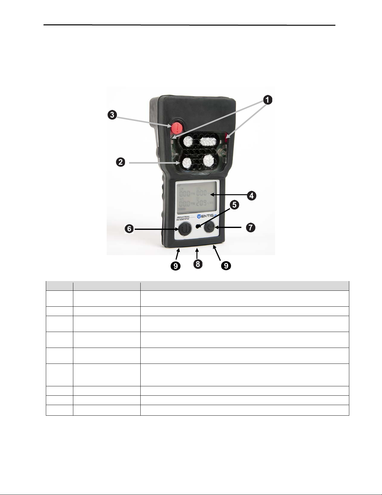
Number
Feature
Functions
1
Visual alarm indicator
Signals an alarm or warning; frequency varies by alarm level. Also used as a
confidence indicator.
2
Sensor ports
Air intake; calibration and bump test gas intake.
3
Panic button
Used to signal an alarm on the instrument and wirelessly to the communications
center.
4
LCD display
User interface; backlight flashes when monitor is in system, high, or low alarm
states.
5
Audible alarm ports
On when monitor is in system, high, or low alarm states; frequency and tone vary
by alarm level. Also used for warnings and as confidence indicator.
6
On/Off/Mode button
Used to power-on and power-off. Also used to bypass a process/step or advance
configuration mode.
7
Enter button
Used to begin a process/step in a process. Edits values in configuration mode.
8
IrDA interface
Indicates infrared light data exchange in-progress.
9
Charging contacts
Battery charging.
Monitor Overview
Hardware Features and Functions
to a next screen in both gas monitoring and configur ati on mo des. Sets va lue s in
8 © Industrial Scientific Corporation
Ventis LS Product Manual
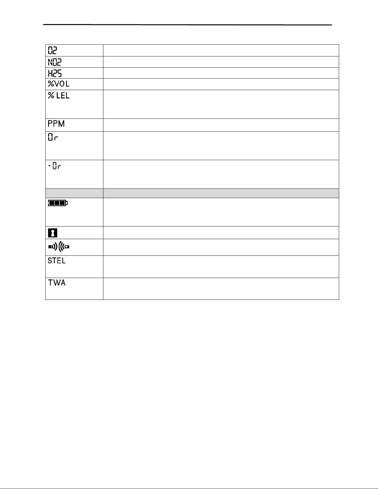
Top Row Icons
Definition
Status: indicates no monitor or sensor faults.
Warning: indicates monitor or sensor fault.
Zero: communicates zero status (e.g., zero results, zero in-progress, etc.).
Gas Cylinder: communicates calibration related information (calibration due, calibration apply
gas, etc.).
Clock: indicates a process is in-progress.
Calendar: communicates overdue warnings for service items (calibration, bump testing, etc.).
Alarm: indicates an alarm causing condition.
Low level audio alarm is on.
High level audio alarm is on.
Peak: displayed when peak detection values are viewed.
Alpha-numeric
display values
Definition
Carbon Monoxide (CO)
Methane (CH4)
Sulfur Dioxide (SO2)
Lower Explosive Limit. Display variations:
“UEG” (German)
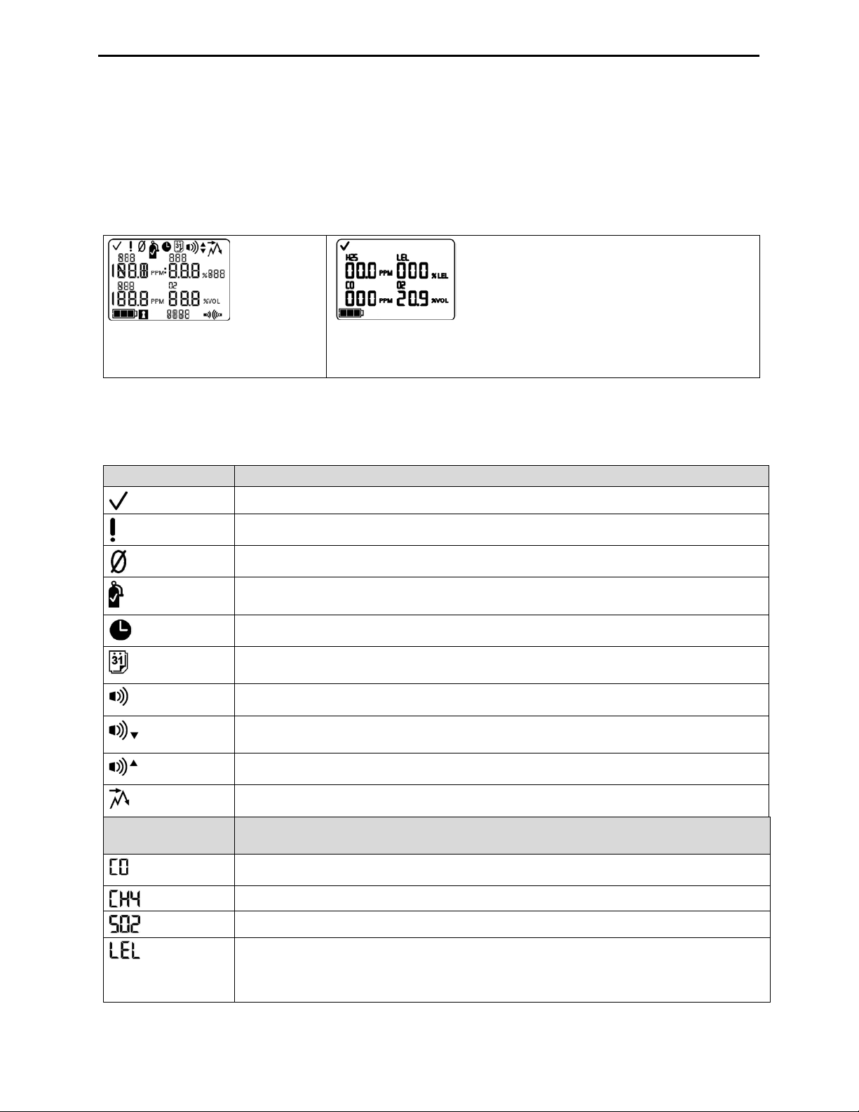
Display Screen
The Ventis LS Boot-up Screen, as shown below, serves to introduce all icons and the alpha-numeric items (e.g.,
8.8.8) that can appear on the display when the monitor is in use, docked, or charging. Each display item is stationary,
communicates unique information, and appears only when relevant to the task being performed.
A sample Gas Monitoring Screen is also shown below, next to the boot-up screen. This illustrates how the icons and
the alpha-numeric characters work together to communicate several points of information to the monitor user.
Boot-Up Screen
All possible screen images.
Gas Monitoring Screen
Sample screen in gas monitoring mode.
It is helpful to view the boot-up screen in sections. The top and bottom rows each contain icons. The main function of
the middle section, in gas monitoring mode, is to communicate gas concentration readings. Definitions for all icons,
gas name abbreviations, gas measurement unit s, and oth er indi cators are provided below. Where appl icable, display
variations are noted.
“LEL” (English)
“LIE” (French)
© Industrial Scientific Corporation
9
Ventis LS Product Manual
Oxygen (O2)
Nitrogen Dioxide (NO2)
Hydrogen Sulfide (H2S)
Percentage Volume: O
and CH4 measurement unit
Percentage unit for combustible gases; display variations:
“% UEG” (German)
Parts Per Million: H2S, CO, SO2 and NO2 measurement unit.
Over-range: for any sensor in over-range, indicates the measured gas concentration is greater
“Sup” (French)
Negative Over-range: for any sensor in negative over-range indicates the measured gas
“InF” (French)
Bottom Row Icons
Definition
Battery level indicator; display v ariations:
3 bars = 67% – 100% charge remaining
Security Code: indicates code is set or to be entered.
Indicates IrDA communication is in-progress when the monitor is docked.
Indicates wireless communication is active when the monitor is NOT docked.
Short Term Exposure Limit: communicates STEL values. Display variations:
“VLE” (French)
Time Weighted Average: communicates TWA values. Display variations:
“VME” (French)
2
“% LEL” (English)
“% LIE” (French)
than the measurement range of the sensor. Display variations:
“Or” (English and German)
concentration is less than the negative measurement range of the sensor. Display variations:
“-Or” (English and German)
1 bar < 33% charge remaining
2 bars = 34% - 66% charge remaining
“STEL” ( English and German)
“TWA” (English and German)
10 © Industrial Scientific Corporation

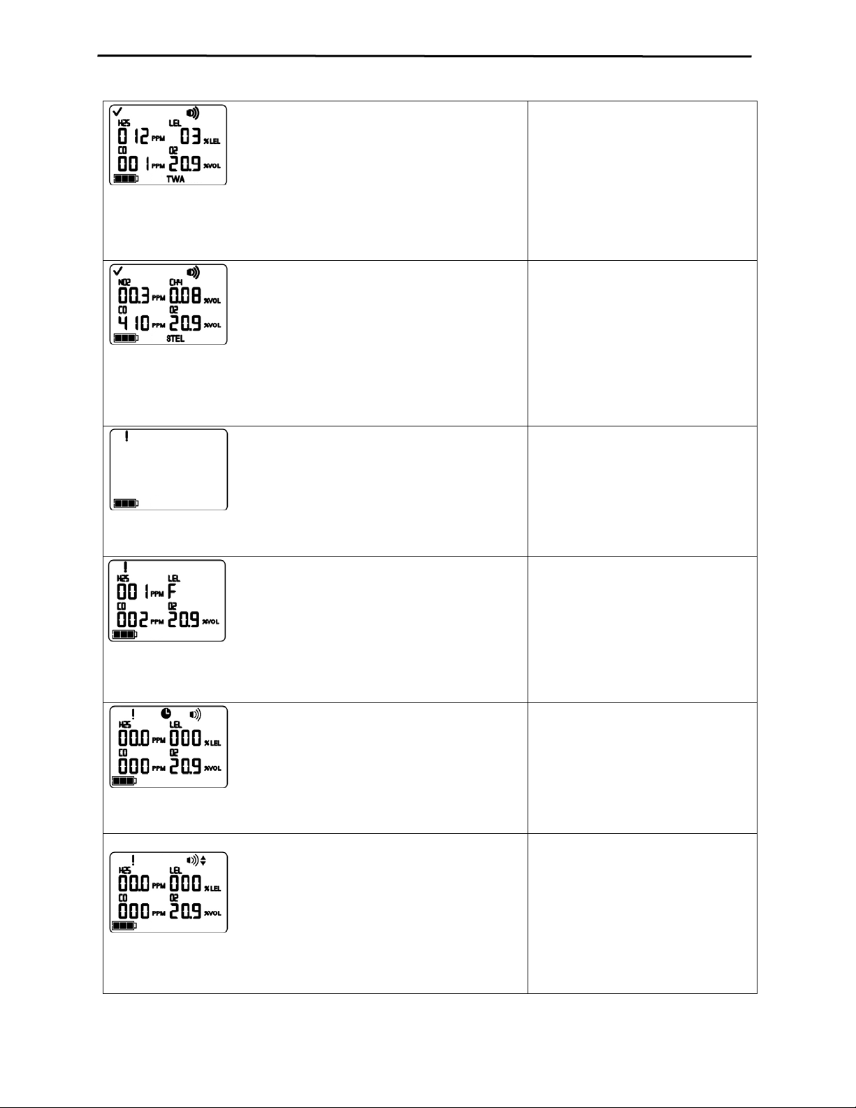
Ventis LS Product Manual
Display
Description
The high level alarms turn on and the alarm icon displays.
An over-range condition occurs when
readings*. The high level alarms turn on and the alarm icon displays.
A negative over-range condition occurs
displays.
A high alarm condition occurs when
displays.
A low alarm condition occurs when the
Alarms
NOTICE
→ All monitor alarms and warnings should be taken seriously and responded to as stated in company safety
standards.
It is practical for the monitor user to be aware of the possible alarms prior to monitor set-up and use. The Ventis LS
has multiple alarm and warning signals. A “system level” alarm generates the highest frequency tone and highest
level visual and vibration signals. It is used to indicate such events as a sensor failure. Compared to the system
alarm, gas alarms are of lower intensity, and a quick repetitive burst of signals is used to indicate a panic or motion
alarm. The lowest level indicator is a warning with low-level beep patterns to indicate service needs (e.g., low battery
or calibration due). The beep is also used as a confidence indicator when enabled.
Alarm types and their alarm generating conditions are described below.
the gas concentration value sensed is
above the sensor’s measuring range.
Over-range Alarm Screen
The “Or” message indicates which sensor(s) is reading an over-range
condition(s). All other sensors show their curre nt gas con cen t r ation
readings on a numeric display (left) or gas names on a text display (right).
After any over-range alarm, th e
monitor should be calibrated.
NOTE: The O2 and toxic sensor values normally
reset when the gas sensed reaches an acceptable
range. If the LEL sensor reads over-r an ge, t he
alarm “latches” or remains on until the monitor is
powered-off.
Negative Over-range Alarm Screen
The “-Or” message indicates which sensor is reading a negative overrange condition. All other sensors display their current gas concentration
High Alarm Screen
A flashing gas concentration value* indicates which sensor(s) reading(s) is
the cause for alarm. The high level alarms turn on and the up arrow icon
Low Alarm Screen
A flashing gas concentration value* indicates which sensor(s) reading(s) is
the cause for alarm. The low level alarms turn on and the down arrow icon
when the gas concentration value
sensed is less than the sensor’s
measuring range.
After any negative over-range alarm,
the monitor should be calibrated.
the concentration of gas sensed
reaches a level greater than the
monitor’s high alarm value setting for a
sensor(s).
concentration of gas sensed reaches
the monitor’s low alarm value setting
for a sensor(s).
© Industrial Scientific Corporation
11
Ventis LS Product Manual
flashes.
A TWA alarm occurs when the
The STEL alarm occurs when the short
The system level alarms turn on and the error icon displays.
Alarm occurs when the monitor
alarm turns on and the error icon displays.
Alarm occurs when any installed
The panic-motion alarm signals turn on.
The Motion 1 alarm occurs when the
The Motion 2 alarm occurs when the
calculated time weighted average
reaches the monitor’s hazardous value
for the set time frame.
TWA Alarm Screen
A flashing gas concentration value* indicates which sensor(s) reading(s) is
the cause for alarm. The low level alarms turn on and the TWA icon
STEL Alarm Screen
A flashing gas concentration value* indicates which sensor(s) reading(s) is
the cause for alarm. The low level alarms turn on and the STEL icon
flashes.
No Sensor Installed Screen
term exposure value exceeds the
acceptable limit.
registers no sensors installed.
sensor’s data-relat ed operations fail
and the sensor is not operational.
Sensor Data Fail Screen
A flashing “F” indicates which sensor is the cause for alarm. The audio
Motion 1 Alarm Screen
Motion 2 Alarm Screen
The panic-motion alarm signals turn on.
instrument has not moved for 1 minute
(default setting; subject to change). To
turn off the alarm, the user can move
the monitor or press the ENTER
button.
Motion 1 alarm has not been cleared.
The user can clear the Motion 2 alarm
by pressing the ENTER button for one
second.
12 © Industrial Scientific Corporation
 Loading...