

Part Number: 17153100-1
Version 2
Six-Unit Calibration Station
for VentisTM
Product Manual
Set-up
Operation

Product Manual for the Six-Unit Calibration Station for Ventis™
2 © 2010, 2016 Industrial Scientific Corporation
TABLE OF CONTENTS
Warnings and Cautionary Statements .................................................................. 3
Capabilities ........................................................................................................... 4
Unpacking the Station .......................................................................................... 6
User Interface ....................................................................................................... 7
Station Preparation ............................................................................................... 8
Hardware Overview (Front) ............................................................................. 8
Hardware Overview (Back) .............................................................................. 9
Software Installation and Hardware Connections .......................................... 10
Station Use ......................................................................................................... 12
Power-on and -off .......................................................................................... 12
Start-up Mode ................................................................................................ 12
Idle Mode ....................................................................................................... 14
Set-up Mode .................................................................................................. 14
Docking and Removing the Instrument .......................................................... 20
Calibration and Bump Testing ....................................................................... 21
Status and Error Messages ........................................................................... 24
Software Use ...................................................................................................... 30
Software Functions ........................................................................................ 30
Using the Software ........................................................................................ 31
Diagnosing Common Problems .......................................................................... 42
Specifications ..................................................................................................... 42
Performance Specifications ................................................................................ 43
Warranty ............................................................................................................. 44
Contact Information ............................................................................... Back cover
###
Product Manual for the Six-Unit Calibration Station for Ventis™
© 2010, 2016 Industrial Scientific Corporation 3
WARNINGS AND CAUTIONARY STATEMENTS
WARNING: Read and understand this manual before operating the
equipment.
WARNING: Failure to perform certain procedures or note certain
conditions may impair the performance of this product. For
maximum safety and optimal performance, please read and follow
the procedures and conditions listed below.
CAUTION: For safety reasons, this equipment must be operated and
serviced by qualified personnel only.
CAUTION: Equipment is rated for indoor use only at altitudes below
2,000 m (6,000’).
CAUTION: Compressed gas cylinders and their contents may
present specific hazards to the user. Use only in a well-ventilated
area. Use only in accordance with the instructions and warnings as
marked on the cylinder and the appropriate Material Safety Data
Sheets.
NOTE: The station should be cleaned only with a soft cloth; do not
use solvents or other liquids.
NOTE: This equipment has been tested and found to comply with the
limits for a Class A digital device, pursuant to part 15 of the FCC
Rules. These limits are designed to provide reasonable protection
against harmful interference when the equipment is operated in a
commercial environment. This equipment generates, uses, and can
radiate radio frequency energy; if it is not installed and used in
accordance with the instruction manual, it may cause harmful
interference to radio communications. Operation of this equipment in
a residential area is likely to cause harmful interference in which case
the user will be required to correct the interference at the user’s own
expense.
Contact your service representative immediately if you suspect that the station is
working abnormally.
###

Product Manual for the Six-Unit Calibration Station for Ventis™
4 © 2010, 2016 Industrial Scientific Corporation
CAPABILITIES
The V•CalTM is a stand-alone calibration station designed to work in conjunction
with Ventis
TM
Multi-gas Monitors. It supports up to six instruments and is
available in three models based on cradle configuration.
Cradle configurations.
Six cradles for aspirated instruments only
Six cradles for diffusion instruments only
Three cradles for aspirated instruments only and three cradles for diffusion
instruments only
Regardless of cradle configuration, each station has three cradles on the back
row and three on the front row. As shown below, the cradles are numbered one
through six, from left to right, from front row to back row.
The station has three internal pumps. Each pump controls two cradles. For
example, as noted below, internal pump 1 controls cradles 1 and 4.
Cradle numbe
r
Back row 4 5 6
Front row 1 2 3
Internal pump 1 2 3
Each internal pump has a solenoid that controls the flow of gas (and fresh air) to
the cradles. These solenoids are referred to in this manual as “cradle solenoids”.
A fourth solenoid, referred to as the “gas solenoid”, controls the flow of calibration
gas and fresh air from the station's intake ports.
The station communicates directly with up to six docked instruments to perform
bump tests and calibrations. It can also charge up to six instruments equipped
with rechargeable Lithium-ion (Li-ion) battery packs.
Calibration and bump test records are saved to the station’s memory which can
store a total 12,000 records. The results for each calibration and bump test
performed are automatically sent, in report form, to an external serial printer (via
an RS232 connection) when connected.
The station can communicate with a host PC across a USB connection, when the
PC is running Accessory Software. The following capabilities are included in the
calibration station with respect to commands from the host PC.

Product Manual for the Six-Unit Calibration Station for Ventis™
© 2010, 2016 Industrial Scientific Corporation 5
Accessory Software enabled capabilities for the host PC.
Read and write instrument and calibration station settings.
Read the instrument data log.
Read the instrument event log.
Access bump test and calibration records from the station.
The following operating systems support Accessory Software:
Windows XP
Windows Vista
Windows 7
Windows 8
###
Product Manual for the Six-Unit Calibration Station for Ventis™
6 © 2010, 2016 Industrial Scientific Corporation
UNPACKING THE STATION
The station’s box contains the items listed below. Each item should be accounted
for in the unpacking process.
Quantity
Part
Number
Description
1
18107664
V
Cal Six-Unit Calibration Station
Each aspirated cradle is fitted with a tube 0.1524 m
(6") in length. The tubing is attached to the cradle's
instrument inlet at one end; the white fitting on the
other end is attached to the cradle inlet. See
manual section, Hardware Overview.
NOTE: one 0.1524 m (6”) tube with a t-fitting is
provided for each aspirated cradle.
1
17093659 Urethane tubing 1.219 m (4’)
1
17121310 USB cable
1
17118027 Fitting (for calibration gas port)
1
17124074 Fitting (for fresh air port)
1
17121070 Industria l Scientific Accessory Software Suite CD
1
17124447 Data-link manual
1
17135864 Service card
1
17123787 Warranty card
1
17153158 Reference to online manual
1
17136623
Power supply with plug adapters (North American,
Europlug, UK/Ireland, and Australia)
Reporting a problem. After unpacking, if any item is missing or appears to have
been damaged, contact Industrial Scientific Corporation (ISC) or a local
distributor of ISC products. Please refer to the manual section, Contact
Information.
###

Product Manual for the Six-Unit Calibration Station for Ventis™
© 2010, 2016 Industrial Scientific Corporation 7
USER INTERFACE
The calibration station user interface is comprised of the following.
Character LCD display
Two pushbuttons
Six sets of three LEDs (one set for each cradle)
The LCD is a twenty-character by two-line display. It is backlit when the station
performs a task or displays the result of a task. The user can select one of four
display languages for the LCD, English, Spanish, French, or German.
The LCD continuously shows status (or error) messages for each docked
instrument. Messages can display for two instruments at a time on the LCD.
Each message is preceded by a cradle number (1, 2, 3, 4, 5, or 6) to indicate
which instrument the message applies to. For example, when displayed together,
these messages indicate that the instrument in cradle 1 passed calibration and
the instrument in cradle 2 failed calibration.
1-Cal Passed
2-Cal Failed
Throughout this manual, any LCD message that indicates the status of a
particular cradle has the designation, “X-“. For example, “X-Cal Passed” where X
will display on the LCD as 1, 2, 3, 4, 5, or 6.
The station’s two pushbuttons, “BUMP” and “CALIBRATE”, are used to initiate
the performance of those functions when one or more instruments are docked.
These buttons are also used to access the station’s set-up mode where a variety
of station settings can be set or changed, and where the user can access station
procedures (e.g., printing).
Each set of LEDs is associated with a particular cradle and has a green, amber,
and red indicator (from left to right). The LEDs are used in combination with
messages on the LCD to indicate the status of each cradle.
The green LED indicates the docked instrument has passed a calibration or
bump test.
The amber LED indicates a calibration or bump test is in-progress or
pending, or that the instrument is charging.
The red LED indicates the docked instrument has failed a calibration or
bump test. The red LED can also indicate an error has occurred.
Product Manual for the Six-Unit Calibration Station for Ventis™
8 © 2010, 2016 Industrial Scientific Corporation
STATION PREPARATION
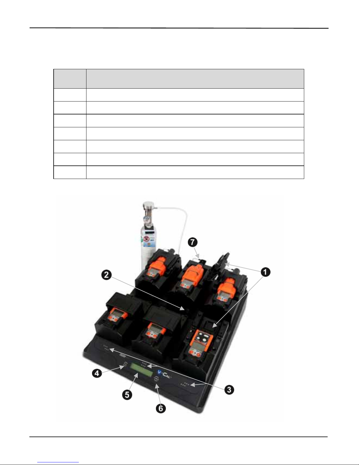
Hardware Overview (Front)
Diagram
Number Feature
1 Cradle lid
2 Cradle lid latch (diffusion cradles only)
3 LED indicators
4 Bump button
5 LCD display
6 Calibrate button
7 Instrument inlet
Product Manual for the Six-Unit Calibration Station for Ventis™
© 2010, 2016 Industrial Scientific Corporation 9
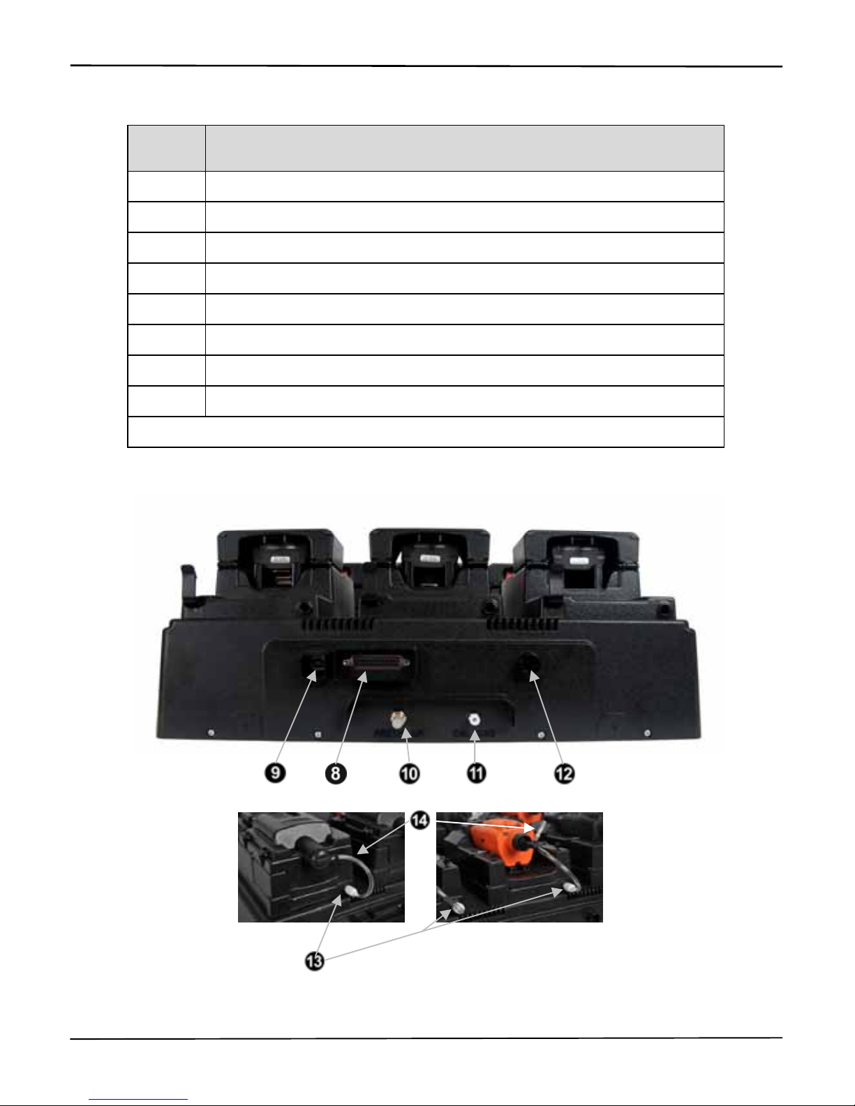
Hardware Overview (Back)
Diagram
Number Feature
8 Printer port
9 USB port
10 Fresh air port
11 Calibration gas port
12 Power input
13* Cradle inlet
14* Cradle tubing (for use when station door in attached)
14* Cradle tubing with T-fitting (for use when station door is removed)
*Aspirated cradles only.
Product Manual for the Six-Unit Calibration Station for Ventis™
10 © 2010, 2016 Industrial Scientific Corporation
Software Installation and Hardware Connections
To identify the parts referenced in the following instructions, refer to the above
manual sections, Hardware Overview and Unpacking the Station.
SOFTWARE INSTALLATION
1 To install the software, insert the software CD into the CD drive of the host
PC. The InstallShield Wizard program automatically starts and begins the
installation process. If the program does not start, open a window on the
computer to view the contents of the CD; double-click on the file titled,
“Setup.exe”.
2 To complete the installation, continue following the instructions as they
display on the PC.
Be sure to choose the desired language for the software user interface.
This is completed from the drop-down menu that appears on one of the
first installations screens. The choices are Chinese (simplified), English
(United States), French (Standard), German, or Spanish. Highlight the
desired language and click the “OK” button to continue.
HARDWARE CONNECTIONS
Attaching cables and cords.
1
USB cable.
o On the back of the station, locate the port marked “USB”.
o To connect the station to the computer, insert the cable’s flat end into
the computer’s USB port; plug the other end into the USB port on the
back of the station.
2
Printer connection (if desired).
o Connect the printer cord to the port marked “printer” on the back of the
station.
o Tighten the captive screws to secure the connection.
3
Power supply.
o On the back of the station, locate the power input marked, “12VDC”.
o Connect the power supply to the 12VDC input.
Product Manual for the Six-Unit Calibration Station for Ventis™
© 2010, 2016 Industrial Scientific Corporation 11
Connecting the gas cylinder and demand flow regulator.
1 Attach the demand flow regulator to the gas cylinder and turn clockwise to
tighten.
2
On the back of the station, locate the inlet marked, “CAL GAS”.
Connect either end of the supplied 1.219 m (4’) urethane tubing to the
CAL GAS inlet. Connect the other end to the regulator’s nipple; the
nipple fits inside the tubing.
FOR ASPIRATED CRADLES
ONLY
.
Enabling the flow of calibration gas to the instrument.
The station can perform calibrations and bump tests with the cradle door
attached to the station (Option 1) OR removed from the station (Option 2). To
enable the flow of calibration gas to the docked instrument, follow the instructions
below for option 1 OR option 2.
Option 1: the instrument door remains attached to the cradle.
NOTE: The station ships from the factory with this op tion enabled.
1 Locate the cradle inlet on the back of the cradle.
2 Locate the tubing that has a white fitting at one end; the other end of the
tubing has no other fittings.
Fasten the white fitting to the cradle inlet; turn clockwise to tighten.
Attach the other end of the tubing to the cradle's instrument inlet.
Option 2: the instrument door is removed from the cradle.
1 Detach the tubing from the cradle inlet.
2 Lift the door to remove it from the cradle; set the door and its tubing aside
or store for future use.
3 Locate the tubing that has a white fitting at one end and a t-fitting at its
other end.
Fasten the white fitting to the cradle inlet; turn clockwise to tighten.
Attach the other end of the tubing directly to the inlet of a docked
instrument.
###

Product Manual for the Six-Unit Calibration Station for Ventis™
12 © 2010, 2016 Industrial Scientific Corporation
STATION USE
Power-on and -off
To power-on the station, plug the power supply into the power source. To poweroff the station, unplug the power supply. There is no power-on/-off switch.
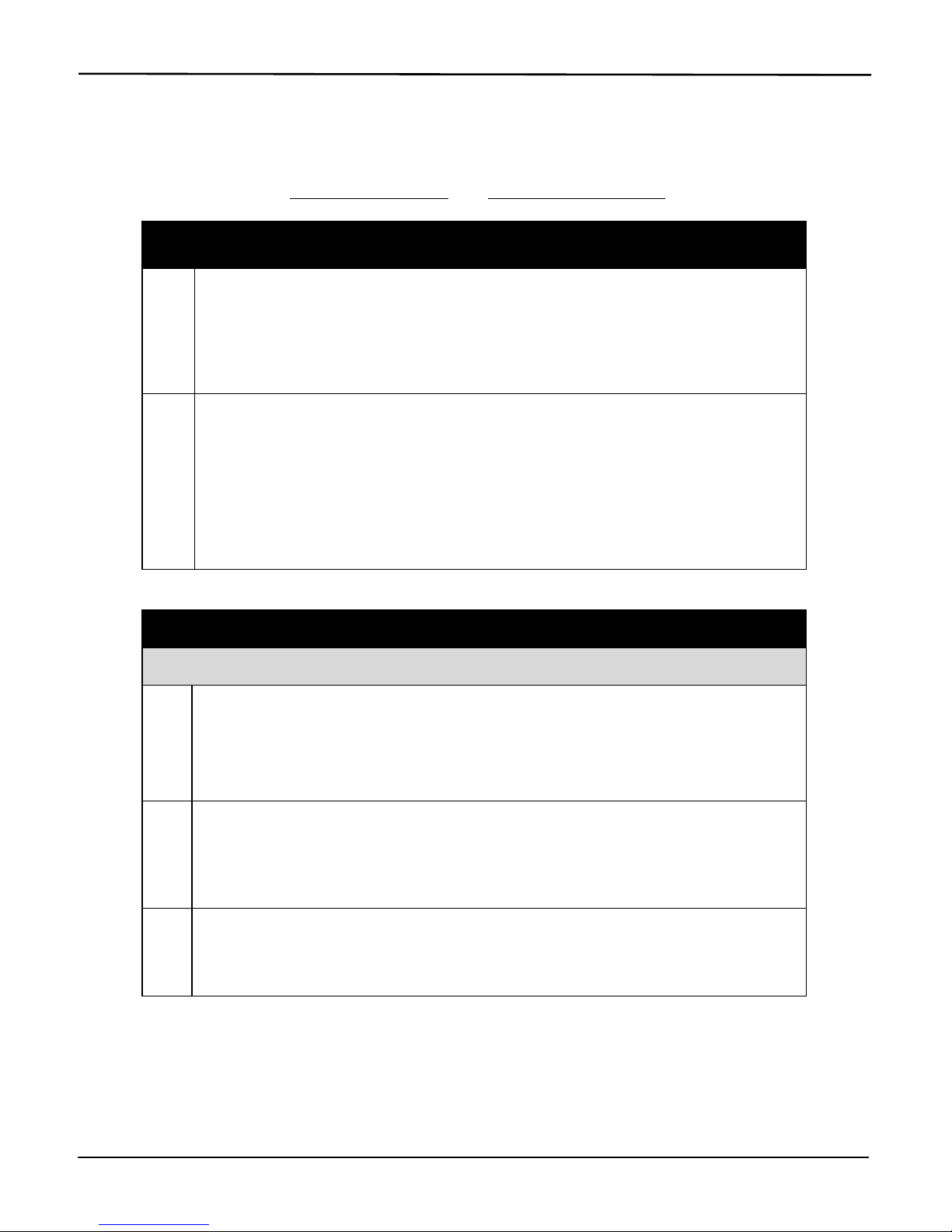
Start-up Mode
When powered-on, the station performs a series of internal diagnostics as
described below.
If the station fails any diagnostic test, the red LEDs turn on for all affected
cradles. A system error message displays on the LCD to describe each failure
encountered. These messages are defined in the manual section, Status and
Error Messages.
DISPLAY INSTRUCTIONS
V·Cal 6-Unit
Calibration Station
No user action required.
V·Cal
v 1.00.07
Displays station name and software version
number (shown: v 3.00.07).
No user action required.
Warming Up
V·Cal
Displays during diagnostic testing of the
system’s pumps, solenoids, board, and
memory.
No user action required.
12345678901234567890
ABCDEFGHIJKLMNOPQRST
Displays to verify the correct operation of the
LCD.
No user action required.
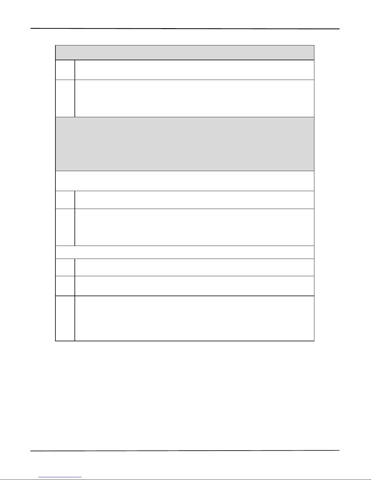
Product Manual for the Six-Unit Calibration Station for Ventis™
© 2010, 2016 Industrial Scientific Corporation 13
Verify
V·Cal LEDs
Displays as the station verifies LED operation.
All six LED sets simultaneously turn on, then
off in this order: red, amber, green, and all.
No user action required.
[ ] [ ]
[ ] [ ]
Displays to verify pixel integrity.
No user action required.
Checking
V·Cal Clock
Displays as the functionality of the real-time
clock is checked.
No user action required.
22 Jan 2010
12:34:56
Displays current date and time (in 24-hour
format) if the clock check was successful.
No user action required.
###
Product Manual for the Six-Unit Calibration Station for Ventis™
14 © 2010, 2016 Industrial Scientific Corporation
Idle Mode
When the "ready" or "charging" messages display for occupied cradles and there
are no station faults, the station is in idle mode. From idle mode, the user can
enter station set-up mode, or can bump test or calibrate docked instruments.
Beginning with set-up mode, each of these processes is outlined in the following
manual sections, Set-up Mode, and Calibration and Bump Testing.
Set-up Mode
From set-up mode, the user can complete station procedures and change station
settings.
Station procedures.
Print alarm events for docked instrument(s)
Print all calibration and bump test records saved to the station
Delete all saved calibration and bump test records from the station
Run station diagnostics
Station settings.
Calibration interval days
Time and date
LCD display language
In set-up mode, each procedure or setting option is presented to the user in the
order shown below. Instructions are provided for completing or bypassing each
task.
NOTE: In set-up mode, when no button is pressed within ten seconds, the message displayed on
the LCD is cleared and the station returns to idle mode.
Access to set-up mode.
From idle mode, simultaneously press BUMP and CALIBRATE; hold for one
second, then release.
DISPLAY MESSAGE INSTRUCTIONS
Print Instrument
Alarm Events
This procedure sends all alarm
event data for the docked
instruments to the printer.
Press BUMP to bypass the procedure;
the user advances to the next set-up mode
feature, Print VCal Records.
Press CALIBRATE to begin the printing
procedure.

Product Manual for the Six-Unit Calibration Station for Ventis™
© 2010, 2016 Industrial Scientific Corporation 15
Print Events
Instrument X
Displays for each cradle with a
docked instrument; allows the user
to confirm (or cancel) the print
command for each instrument.
Press BUMP to bypass printing for the
cradle number shown.
Press CALIBRATE to send the data to
the printer for that cradle’s instrument.
Continue to use the BUMP and
CALIBRATE buttons to print or bypass
the printing for each docked
instrument.
If all printing options are bypassed, the
user advances to the next set-up mode
feature, Print V
Cal Records.
Printing Instrument
Alarm Events
Displays while the instrument
events print.
No user action required.
NOTE: While the events print, the station ignores all
button presses and USB communications.
Print VCal
Records
This procedure sends all bump
test and calibration records from
the station memory to the printer.
Press BUMP to bypass the procedure;
the user advances to the next set-up mode
feature, Clear V
Cal Records.
Press CALIBRATE to begin the printing
procedure.
Print Records?
NO YES
Displays to allow the user to
confirm (or cancel) the print
command.
Press BUMP to cancel the print
command; the user advances to the next
set-up mode feature, Clear V
Cal Records.
Press CALIBRATE to send the data to
the printer.
Printing Record
X of YYY
Displays to indicate printing
progress, where X = the record
number currently printing and YYY
= the total number of records that
are being sent to the printer.
Press BUMP to can cancel any remaining
printouts.
NOTE: After printing the saved bump test and
calibration reports, they are NOT automatically deleted
from the station. The “Clear V
Cal Records” function is
used to complete that task.

Product Manual for the Six-Unit Calibration Station for Ventis™
16 © 2010, 2016 Industrial Scientific Corporation
Clear VCal
Records
This procedure deletes all bump
test and calibration records from
the station memory.
NOTE: The clear records function is
executable regardless of whether or not the
records have been printed.
Press BUMP to bypass the procedure.
The records remain in the station memory
and the user advances to the next set-up
mode feature, Cal Interval Days.
Press CALIBRATE to delete all records
saved to the station.
Clear Records?
NO YES
Displays to allow the user to
confirm (or cancel) the clear
records command.
Press BUMP to cancel the clear records
command. The records remain in the
station memory and the user advances to
the next set-up mode feature, Cal Interval
Days.
Press CALIBRATE to delete all records
saved to the station memory.
VCal Records
Cleared
Displays to indicate the records
have been successfully deleted
from the station's memory.
No user action required.
Cal Interval
30 Days
Displays the current setting for the
number of days between
calibrations (shown: 30).
Allows the user to set the number
of days between calibrations. The
setting is programmed into the
station as well as any docked
instrument.
Press BUMP TEST to bypass the setting
process; the user advances to the next
set-up mode feature, Set Date and Time.
Press CALIBRATE to edit the value for
the calibration interval.
Cal Interval
30 Days
Valid values: 1 – 365 days
Increment: 1 day
Press BUMP to change the value; hold to
speed the increment pace. (After the
counter reaches 365, it starts again at 1.)
Press CALIBRATE to set the value
displayed.

Product Manual for the Six-Unit Calibration Station for Ventis™
© 2010, 2016 Industrial Scientific Corporation 17
Set Cal Interval
On Instruments
Allows the user to set the
calibration interval value on the
docked instrument to match the
station's calibration interval value.
Press BUMP TEST to bypass the setting
process; the user advances to the next
set-up mode feature, Set Date and Time.
Press CALIBRATE to complete the
setting process.
Set Cal Interval?
No Yes
Displays to allow the user to
confirm (or cancel) the setting of
instrument calibration interval
values.
Press BUMP to cancel the setting
process.
Press CALIBRATE to complete the
setting process.
Set Time and Date
22 Jan 2011 13:34:56
Displays the current date and time
(in 24-hour format). Each value
can be changed. Values are
presented to the user in this order:
month, day, year, hour, and
minutes.
Press BUMP TEST to bypass the setting
process; the user advances to the next
set-up mode feature, Select Language.
Press CALIBRATE to edit any of the time
or date values.
Set Time and Date
22 Jan 2011
The first date value subject to
change (year) will blink.
Press BUMP to edit the blinking value, if
needed.
Press CALIBRATE to set the value
displayed.
Continue to use the BUMP and
CALIBRATE buttons, respectively, to
edit and set the next blinking value.
Set Time and Date
13:34
The first time value subject to
change (hour) will blink.
Press BUMP to edit the blinking value, if
needed.
Press CALIBRATE to set the value
displayed.
Continue to use the BUMP and
CALIBRATE buttons, respectively, to
edit and set the next blinking value.

Product Manual for the Six-Unit Calibration Station for Ventis™
18 © 2010, 2016 Industrial Scientific Corporation
Select Language
English
Displays the language setting
currently in use by the station.
Allows the user to choose one of
four language options for the
station's LCD.
Press BUMP TEST to bypass the setting
process and advance to the next set-up
mode feature, System Check procedure.
Press CALIBRATE to edit the language
selection, if needed.
Select Language
English
The language selection options
are presented to the user in this
order: English (shown), Espanol,
Francais, and Deutsch.
Press BUMP to bypass the displayed
language. Continue to press BUMP until
the desired language displays.
Press CALIBRATE to set the displayed
language.
Change Printer Paper
Allows the user to power-on the
printer. The paper is automatically
fed by the printer when a new roll
is inserted.
Press BUMP to bypass the procedure.
Press CALIBRATE to power-on the
printer. During this time, the V•Cal will
display "Insert New Paper Roll OK".
Press CALIBRATE again to power-off the
printer.
Note: The Insert New Paper Roll OK screen will not
time out, to allow the user as much time as necessary
to change the paper roll.
VCal
System Check
This procedure allows the user to
initiate a diagnostic check of the
system. When selected, the
station will cycle through all
diagnostic tests described in the
manual section, Start-up.
Press BUMP TEST to bypass the
diagnostics procedure and advance to the
Exit Set-up display.
Press CALIBRATE to initiate the station's
system diagnostics.
Exit
Setup
Press BUMP TEST to remain in set-up
mode. The user returns to the first set-up
mode feature, Print Instrument Alarm
Events.
Press CALIBRATE to exit set-up mode
and return to idle mode.

Product Manual for the Six-Unit Calibration Station for Ventis™
© 2010, 2016 Industrial Scientific Corporation 19
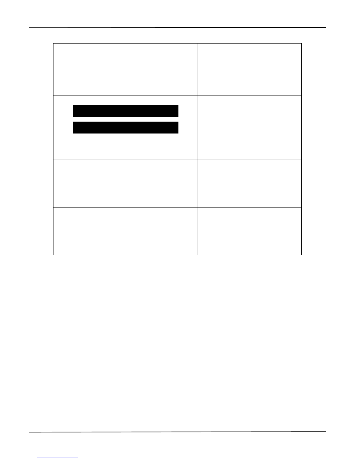
Figure 1 lists the information contained in reports that are generated from the
printing procedures described above: printing instrument events and printing
VCal Records (calibration and bump test reports).
Report information generated from set-up mode functions.
Print Instrument Events
Print VCal Records
Industrial Scientific Corp.
Name of calibration station and its
software version
Date of printout
Instrument serial number
Instrument software version
Instrument hardware version
For each alarm event:
o Sensor type
o Sensor serial number
o Sensor high alarm threshold
o Sensor low alarm threshold
o Peak gas exposure value
during alarm
o Duration of alarm event in
seconds
o Time and date the alarm
occurred
o Instrument user setting
o Instrument site setting
A blank for the user’s signature
A blank for the user to enter the
date
A blank for the user to enter the
time
Industrial Scientific Corp.
Name of calibration station and its
software version
Date and time of calibration (or
bump test)
Instrument serial number
Instrument software version
Instrument hardware version
Instrument zero, calibration, or
bump test result (pass or fail)
Recommended date for next
calibration (shown for calibration
only; date is blank for a failed
calibration)
For each sensor:
o Sensor type
o Span reserve (for calibration)
or Final bump test reading (for
bump test)
o Calibration gas concentration
o High alarm threshold
o Low alarm threshold
o Zero, calibration, or bump test
results
A blank for the user to enter the
cylinder lot number
A blank for the user’s signature
Figure 1a. Event report. Figure 1b. Calibration and bump test reports.
###

Product Manual for the Six-Unit Calibration Station for Ventis™
20 © 2010, 2016 Industrial Scientific Corporation
Docking and Removing the Instrument
STEP INSTRUCTIONS
Docking the ASPIRATED instrument.
1 When the station faces the user, its cradle lid hinge is to the user’s right.
Lift the lid from the left to open the cradle.
2 To properly dock the instrument in the cradle, complete or observe the
following.
The instrument’s display faces the user and its logo is readable.
Press down on the instrument to secure it in the cradle; if needed,
slide the instrument forward to secure.
3 Close the cradle lid.
Docking the DIFFUSION instrument.
1 When the station faces the user, its cradle lid hinge is at the top of the
cradle. Lift up to open.
2 To properly place the instrument in the cradle, complete or observe the
following.
The instrument’s display faces the user and its logo is readable.
Press down on the instrument to secure it in the cradle; if needed,
slide the instrument forward to secure.
3 Close the cradle lid.
Removing the DIFFUSION o
r
A
SPIRATED instrument
1 Lift the cradle lid (as instructed above for an aspirated or diffusion
instrument).
2 Lift the instrument to remove it from the cradle.

Product Manual for the Six-Unit Calibration Station for Ventis™
© 2010, 2016 Industrial Scientific Corporation 21
Calibration and Bump Testing
The station delivers calibration gas to as many as three cradles simultaneously.
After the first three instruments are calibrated (or bump tested), the station
automatically calibrates (or bump tests) any other docked instruments.
The calibration and bump testing processes are described below. During these
processes, various status or error messages may display. The messages can
apply to the station, the instrument, or an accessory. They are described in the
manual section, Status and Error Messages.
The Calibration Process.
To begin the calibration process, press CALIBRATE; hold for three seconds
and release. The station runs a check to determine if any instruments were just
calibrated.
NOTE: If a printout of the calibration report is desired, ensure the printer is connected to the station.
DISPLAY INSTRUCTIONS
Cradles 1, 2, 5
Cal Again?
Displays to indicate which, if any,
instruments have just been calibrated
and their cradle numbers.
Press CALIBRATE to begin the
recalibration of the instrument(s).
Press BUMP TEST to skip the
recalibration.
X-Warming up
Displays for any instrument that is
charging; indicates the station is
preparing the instrument for calibration.
No user action required.
For all other installed sensor
combinations, the Zero in Progress
message displays next.
X-Zero in Progress
Displays during the zero process which
requires approximately 15 seconds to
complete. The amber LEDs turns on for
each affected cradle.
If an instrument's only installed sensor is
O2, a pending message displays in
place of the zero in-progress message.
No user action required.

Product Manual for the Six-Unit Calibration Station for Ventis™
22 © 2010, 2016 Industrial Scientific Corporation
X-Zero Passed
X-Zero Failed
Displays along with a red or green LED
to indicate which instruments have
passed (green) or failed (red) the zero
process.
The instrument LCD indicates which
sensor(s) is in failure.
No user action required.
The station automatically cancels the
calibration for any affected cradle.
X-Cal in Progress
Displays during the calibration process.
The amber LED turns on for each
affected cradle.
No user action required.
The station reads and applies the
calibration gas settings from the
instrument.
X-Cal Passed
X-Cal Failed
Displays along with a red or green LED
to indicate which instruments have
passed (green) or failed (red) calibration.
The calibration report for each
instrument is sent out the RS232 port for
printing and is saved to the station.
Remove the instrument from the
cradle to clear the display.
NOTE: The instrument must pass a zero and/or
calibration before it is useable.

Product Manual for the Six-Unit Calibration Station for Ventis™
© 2010, 2016 Industrial Scientific Corporation 23
The Bump Test Process.
To begin the bump test process, press BUMP TEST; hold for three seconds and
release.
NOTE: If a printout of the calibration report is desired, ensure the printer is connected to the station.
DISPLAY INSTRUCTIONS
X-Warming up
Displays for any instrument that is
charging; indicates the station is
preparing the instrument for bump
testing.
No user action required.
X-Bump in Progress
Displays during the bump test
process. The amber LED turns on for
each affected cradle.
The gas name abbreviation and
calibration gas value for each sensor
display as that sensor is bump tested.
For example, "X-25.0 ppm H2S".
No user action required.
The station reads and applies the bump
test parameters (gas percentage and
response time settings) from the
instrument.
The station determines if any installed
sensor for any instrument is in a
calibration fail or zero fail state. For
those instruments, the station
automatically cancels the bump test
and performs a calibration. If the
calibration is successful, the station
then automatically bump tests the
instrument(s).
X-Bump Passed
X-Bump Failed
Displays along with a red or green
LED to indicate which instruments
have passed (green) or failed (red)
the bump test.
The calibration report for each
instrument is sent out the RS232 port
for printing and is saved to the station.
The station automatically calibrates any
instruments that failed the bump test.
Each cradle's bump test result display
clears when the instrument is removed
from the cradle.

Product Manual for the Six-Unit Calibration Station for Ventis™
24 © 2010, 2016 Industrial Scientific Corporation
Status and Error Messages
As noted below, status and error messages can apply to the station, the
instrument, or an accessory.
Station-related Status and Error Messages.
The user can take corrective actions as noted. When no corrective action is
noted, contact ISC or a distributor of ISC products for technical support.
NOTE: All station related errors are logged and saved to the station’s memory. This aids in the
diagnosis and correction of technical service issues.
MESSAGE INSTRUCTION
Busy
Please Wait
Displays when the USB is downloading
data or communicating with the station.
No user action required.
The bump test and calibrate
functions are not available.
Set-up mode is not accessible.
USB communications are
accepted and processed.
Check
VCal Pump X
Or
X-Check Pump
Displays to indicate which of the station’s
three pumps has failed. The red LED
turns on for each affected cradle.
Contact factory.
Bump test and calibration
functions are not available for
the affected cradles.
Set-up mode is accessible.
USB communications are
accepted and processed.
Check VCal
Gas Solenoid
Displays to indicate the main gas/air
intake solenoid is not operating properly.
This affects the flow of gas or air to all six
cradles; all six red LEDs turn on.
Contact factory.
Bump test and calibration
functions are not available.
Set-up mode is accessible.
USB communications are
accepted and processed.

Product Manual for the Six-Unit Calibration Station for Ventis™
© 2010, 2016 Industrial Scientific Corporation 25
Check VCal
Cradle Solenoid X
Or
X-Check Solenoid
Displays to indicate when any solenoid is
not operating properly. The red LED and
the display indicate which cradle numbers
are affected.
Contact factory.
Bump test and calibration
functions are not available for
the affected cradles.
Set-up mode is accessible.
USB communications are
accepted and processed.
Check
VCal Board
Displays to indicate the board current falls
outside the acceptable limits (or may
indicate an oscillator or A/D failure). All six
red LEDs turn on.
Contact factory.
Bump test and calibration
functions are not available.
Set-up mode is accessible.
USB communications are
accepted and processed.
VCal Memory
Error
Displays to indicate the station cannot
read from or write to its memory. All six
red LEDs turn on.
Contact factory.
The bump test and calibrate
functions are not available.
Set-up mode is accessible.
USB communications are
accepted and processed.
VCal Clock
Error
Indicates an invalid date or clock setting
on the station’s real-time clock. All six red
LEDs turn on.
The user can enter set-up mode
and attempt to re-set the date and
time. (See the manual section, Setup Mode.)
Bump test and calibration
functions are not available.
Set-up mode is accessible.
USB communications are
accepted and processed.

Product Manual for the Six-Unit Calibration Station for Ventis™
26 © 2010, 2016 Industrial Scientific Corporation
Cradle-, Instrument-, and Accessory-related Status and Error Messages.
The user can take corrective actions as noted below. The user can also consult
the appropriate instrument or accessory manual. When no corrective action is
noted, contact ISC or a distributor of ISC products for technical support.
MESSAGE INSTRUCTION
X-Ready
Displays when an instrument is installed
and is not charging. The green LED turns
on for each affected cradle.
The bump test and calibrate
functions are available.
Set-up mode is accessible.
USB communications are
accepted and processed.
X-Charging
Displays to indicate the station is charging
an instrument equipped with a Li-ion
battery. The amber LED turns on for each
affected cradle.
NOTE: Always refer to the instrument’s battery icon to
assess the level of charge.
The bump test and calibrate
functions are available.
Set-up mode is accessible.
USB communications are
accepted and processed.
X-Close Lid
May display when a bump test or
calibration is started. Indicates a cradle lid
is not closed; the red LED turns on for
each affected cradle.
Ensure the cradle lid is closed.
When the lid is successfully closed
the display message for the affected
cradle(s) indicates a status of
"pending"; the amber LED turns on.
The station will complete any
calibrations (or bump tests) already
in-progress. It will then
automatically complete any pending
calibrations (or bump tests).

Product Manual for the Six-Unit Calibration Station for Ventis™
© 2010, 2016 Industrial Scientific Corporation 27
X-Pending
Displays during the zero process for any
docked instrument equipped with only an
O2 sensor.
Displays during the bump test or
calibration processes for any instrument
in queue for calibration.
Displays after a “Close Lid” error has
been encountered and successfully
addressed by the user.
The amber light turns on for each affected
cradle.
No user action required.
X-Waiting to Connect
Y-Waiting to Connect
Displays as the station attempts to
communicate with a docked instrument.
The amber LED turns on for each affected
cradle.
If communication with the instrument is
established within three minutes, one of
two messages displays depending on the
status of the battery: X-Charging or XReady.
If communication is not established within
three minutes, this error message
displays: X-Inst Comm Error.
No user action required.
The bump test and calibrate
functions are available.
Set-up mode is accessible.
USB communications are
accepted and processed.
X-Inst Comm Error
Displays if the bump test or calibrate
process is started and the station cannot
establish communication with the
instrument. The red LED turns on for each
affected cradle.
The calibration or bump test is
automatically aborted.
Set-up mode is accessible.
USB communications are
accepted and processed.
Press BUMP TEST or
CALIBRATION to attempt the
process again. If unsuccessful the
display persists until the instrument
is removed from the station.

Product Manual for the Six-Unit Calibration Station for Ventis™
28 © 2010, 2016 Industrial Scientific Corporation
X-Instrument Error
Indicates the docked instrument is in a
system alarm condition. A system alarm
occurs when the aspirated instrument’s
pump is not operating correctly. The red
LED turns on for each affected cradle.
The calibration bump test or is
automatically aborted by the station.
The display persists until the
instrument is removed from the
station.
The bump test and calibrate
functions are not available.
Set-up mode is not accessible.
USB communications are
accepted and processed.
Ensure the instrument's pump and
the cradle's instrument inlet are
clear and free of debris; dock the
instrument again. If the message
persists, the instrument’s pump may
be in need of factory service or
replacement.
X- Sensor Error
Indicates the docked instrument has one
or more failed sensors.
The instrument LCD indicates which
sensor(s) is in failure. The user can
attempt to correct the error by
replacing the sensor(s).
Error – Cradle X
Cal Gas Mismatch
Displays during a bump test or calibration
to indicate one of these conditions exists
among the instruments to be calibrated
(or bump tested):
More than 4 different sensor types
are installed.
LEL and CH4 sensor types are
installed in different instruments.
The installed sensor types match, but
the calibration gas concentration
values differ.
The error message indicates the cradle
number of the first mismatched
instrument. The red LED turns on for
each affected cradle.
The calibration or bump test is
automatically aborted by the station.
The display persists until the
instrument(s) is removed from the
station.
Set-up mode is accessible.
USB communications are
accepted and processed.
The user can remove the
mismatched instrument from its
cradle. If the remaining instruments
are not mismatched, the "Ready"
message displays and the bump
test and calibration functions are
available.

Product Manual for the Six-Unit Calibration Station for Ventis™
© 2010, 2016 Industrial Scientific Corporation 29
Printer Fault
Low Temperature
May display when a station attempts to
print. Indicates the temperature inside the
station is below -10°C (14°F).
The printer functions are not
available.
The bump test and calibrate
functions is available after the
Printer Fault screen times out.
Setup mode is accessible after
the Printer Fault screen times
out.
USB communications are
accepted and processed.
###

Product Manual for the Six-Unit Calibration Station for Ventis™
30 © 2010, 2016 Industrial Scientific Corporation
SOFTWARE USE
Software Functions
Accessory Software software functions are organized into categories, and are
presented on the software’s user interface as “tabs”. The tabs are listed below
with descriptions of the functions accessible from each.
TAB FUNCTION/CONTENTS
General Administration information for the instrument.
Options Instrument configuration options.
Users and Sites Shows active user and site saved in instrument (not
viewable on instrument).
Components Shows details of the instrument’s components.
Calibrations Shows calibration data associated with each instrument
(can view saved records or download the latest).
Bump Tests Shows bump test data associated with each instrument
(can view saved records or download the latest).
Event Log Shows log files and associated data for each instrument.
Data Logging Shows data log files and associated data for each
instrument.
Beginning with the General tab, each tab is reproduced in the following pages.
Command icons (or buttons) also appear on each tab and accomplish the
following when selected by the user.
Refresh: generally used when a new instrument is docked to access its data
log, event log, settings, etc.
Update: after editing any value on a tab, the instrument settings are updated
to reflect the new value(s).
Print: opens a new window containing a printable report of the information
relevant to the tab.
Disconnect: returns the user to the Connection form.

Product Manual for the Six-Unit Calibration Station for Ventis™
© 2010, 2016 Industrial Scientific Corporation 31
Using the Software
If Accessory Software is not already running, double-click on the desktop icon to
reach the Connection form. The software can also be started from “Programs”
within the computer’s “Start” menu.
Figure 2. Desktop icon.
Figure 3. Connection form.
Connection options:
Complete the connection to the docked instrument. Choose the appropriate
instrument name, station type, and communications port (the default is the
port with the highest port number). Choose “Connect” to complete the
connection with the installed instrument. The software opens to the main
screen—the “General” tab—where data are editable and the download
function is accessible.
Work offline. Choose “Work offline” to view previously downloaded data and
reports with no device connected to the PC. The next window to open
presents a list of serial number those of instruments available to view offline
(see Figure 4). Highlight the desired serial number and click “Open”. The
software opens to the main screen—the “General” tab. When working offline,
data are not editable and the download function is not accessible.

Product Manual for the Six-Unit Calibration Station for Ventis™
32 © 2010, 2016 Industrial Scientific Corporation
Figure 4. Offline instrument access window.
The software user can highlight an instrument serial number and select “Open” to
view that instrument’s downloaded data. The accessible read-only data includes
that which is associated with these tabs: General, Components, Event Log, and
Data Logging, plus any downloaded calibration and bump test records.

Product Manual for the Six-Unit Calibration Station for Ventis™
© 2010, 2016 Industrial Scientific Corporation 33
Figure 5. General tab.
The opening software screen after connecting to a docked instrument or
connecting to work offline. The fields shown in white are editable. The "Select
Instrument" drop-down allows the user to access the datalog for any installed
instrument.

Product Manual for the Six-Unit Calibration Station for Ventis™
34 © 2010, 2016 Industrial Scientific Corporation
Figure 6. Options tab.
The instrument configuration options can be initially set and subsequently
changed from this screen. A check mark indicates the option is enabled.
Figure 7. Users and Sites tab.
The software user can assign, to the docked instrument, one active user name
and one active site name. This information is saved in the instrument, but not
viewable on the instrument.

Product Manual for the Six-Unit Calibration Station for Ventis™
© 2010, 2016 Industrial Scientific Corporation 35
Figure 8. Components tab.
The components tab lists all components installed in the instrument. The
software user can highlight a component and select “Open” to view and modify
its settings (e.g., Sensor Details window shown below in Figure 9).
Figure 9. Sensor Details window.
The sensor details screen allows the software user to change alarm set points as
well as the calibration gas concentrations for the installed sensors.

Product Manual for the Six-Unit Calibration Station for Ventis™
36 © 2010, 2016 Industrial Scientific Corporation
Figure 10. Calibrations tab.
Lists all certificate files for calibration results that have been downloaded for the
instrument. If the software user highlights a certificate and selects the “Open File”
command, that calibration certificate opens in a new window. When the
“Download” command is selected, all calibration certificates are downloaded from
the station.
Figure 11. Sample Calibration Certificate.
The user can print the certificate if needed.

Product Manual for the Six-Unit Calibration Station for Ventis™
© 2010, 2016 Industrial Scientific Corporation 37
Figure 12. Bump Tests tab.
Lists all certificate files for bump test results that have been downloaded for this
instrument. If the software user highlights a certificate and selects the “Open File”
command, that bump test certificate opens in a new window. When the
“Download” command is selected, all bump test certificates are downloaded from
the station.
Figure 13. Sample Bump Test Certificate.
The software user can print the certificate if needed.

Product Manual for the Six-Unit Calibration Station for Ventis™
38 © 2010, 2016 Industrial Scientific Corporation
Figure 14. Event Log tab.
Lists all downloaded event logs for the docked instrument. If the software user
highlights a log file and selects the “Open File” command, that event log report
opens in a new window. When the Download command is selected, all event logs
are downloaded from the connected instrument.

Product Manual for the Six-Unit Calibration Station for Ventis™
© 2010, 2016 Industrial Scientific Corporation 39
Figure 15. Sample printout for event log.
A similarly formatted report is also available for data logs when the “Print”
command is selected from the Data Logging tab.
Figure 16. Data Logging tab

Product Manual for the Six-Unit Calibration Station for Ventis™
40 © 2010, 2016 Industrial Scientific Corporation
The Data Logging tab lists all downloaded data logs for the docked instrument.
When the “Download” command is selected, all data logs are downloaded from
the connected instrument.
When the user highlights a session, the command buttons will accomplish the
following:
The “Summary” command opens a new window with all sensor data for that
session.
The “Print” command opens in a new window that is similar in content and
format, to the Event Log Report as shown above in Figure 15.
The “Open File” command allows the software user to view the next level of
detail for a highlighted session, as shown below in the Sensor Session data
(Figure 17).

Product Manual for the Six-Unit Calibration Station for Ventis™
© 2010, 2016 Industrial Scientific Corporation 41
Figure 17. Sensor details.
By highlighting a single sensor and clicking on the “Detail” button, the user can
view a complete list of readings for that sensor for that sensor session. The
sensor session can be printed, shown graphically, or exported to a comma
separated variable file by using the “Print”, “Graph”, or “Export” command
buttons, respectively. The “Compare” feature allows the user to compare the
sensor session data for two or more highlighted components.

Product Manual for the Six-Unit Calibration Station for Ventis™
42 © 2010, 2016 Industrial Scientific Corporation
DIAGNOSING COMMON PROBLEMS
Problem Likely Cause(s)
Display is blank… No power to the instrument; check power supply
connections. Display is damaged; contact factory.
Unit resets… Internal error. Cycle the power. If problem persists,
contact factory.
Instrument continually
fails bump test or
calibration…
Ensure calibration gas is connected and the bottle is
full. Sensors may require replacement. Contact
factory.
Printer is not working… Ensure paper is in printer and printer ribbon is in
place.
No communication to
PC…
Ensure application software and the USB driver are
installed on PC.
Ensure USB cable is plugged in.
Ensure the correct COM port is selected on the
Connection window of the software.
V•Cal does not
communicate with
instrument…
Ensure IR ports on both the V•Cal and the instrument
are clean from dirt and debris.
V•Cal PC software will
not connect to
instrument…
Ensure instrument is placed in the instrument cradle.
Ensure IR ports on both V•Cal and instrument are
clean from dirt and debris.
SPECIFICATIONS
Feature Specification
Instruments
supported
Ventis Aspirated with Extended Range Lithium-ion (typical)
Ventis diffusion with Lithium-ion (typical)
Dimensions 465 mm (18.31") X 527 mm (20.75") X 195 mm (7.68")
Gas Inlets One fresh air, one gas cylinder
Pump Flow Rate 500 ml/min
Input Universal AC power supply; 110 / 240 VAC, 50/60 Hz
Communication On-board LEDs give status indication.
Multilingual LCD display shows status and set-up menus.
Real-time readings on the Ventis display during calibration.
Internal memory Stores up to 150 bump test and calibration reports before
overwrite. Memory retains information when power is off.

Product Manual for the Six-Unit Calibration Station for Ventis™
© 2010, 2016 Industrial Scientific Corporation 43
PERFORMANCE SPECIFICATIONS
Category Specification
Operating Temperature Range 0ºC to +50ºC
Storage Temperature -20ºC to +60ºC
Operating Humidity Range
0 to 80% RH up to 31ºC, decreasing
linearly to 50% RH at 40ºC
External Power
Supply Ratings
Supply voltage 110-240 VAC
Frequency range 50/60 Hz
Current Rating 1.5A
Installation Category 2
Pollution Degree 2

Product Manual for the Six-Unit Calibration Station for Ventis™
44 © 2010, 2016 Industrial Scientific Corporation
WARRANTY
Industrial Scientific Corporation's Six-Unit Calibration Station for the Ventis are
warranted to be free from defects in material and workmanship for a period of
one year after purchase.
Limitation Of Liability
INDUSTRIAL SCIENTIFIC MAKES NO OTHER WARRANTIES, EITHER
EXPRESSED OR IMPLIED, INCLUDING BUT NOT LIMITED TO THE
WARRANTIES OF MERCHANTABILITY OR FITNESS FOR PARTICULAR
PURPOSE.
SHOULD THE PRODUCT FAIL TO CONFORM TO THE ABOVE WARRANTY,
BUYER’S ONLY REMEDY AND INDUSTRIAL SCIENTIFIC’S ONLY
OBLIGATION SHALL BE, AT INDUSTRIAL SCIENTIFIC’S SOLE OPTION,
REPLACEMENT OR REPAIR OF SUCH NON-CONFORMING GOODS OR
REFUND OF THE ORIGINAL PURCHASE PRICE OF THE NONCONFORMING GOODS.
IN NO EVENT WILL INDUSTRIAL SCIENTIFIC BE LIABLE FOR ANY OTHER
SPECIAL, INCIDENTAL, OR CONSEQUENTIAL DAMAGES, INCLUDING LOSS
OF PROFIT OR LOSS OF USE, ARISING OUT OF THE SALE,
MANUFACTURE, OR USE OF ANY PRODUCTS SOLD HEREUNDER
WHETHER SUCH CLAIM IS PLEADED IN CONTRACT OR IN TORT,
INCLUDING STRICT LIABILITY IN TORT.
It shall be an express condition to Industrial Scientific’s warranty that all products
be carefully inspected for damage by Buyer upon receipt, be properly calibrated
for Buyer’s particular use, and be used, repaired, and maintained in strict
accordance with the instructions set forth in Industrial Scientific’s product
literature. Repair or maintenance by non-qualified personnel will invalidate the
warranty, as will the use of non-approved consumables or spare parts. As with
any other sophisticated product, it is essential and a condition of Industrial
Scientific’s warranty that all personnel using the products be fully acquainted with
their use, capabilities, and limitations as set forth in the applicable product
literature.
Buyer acknowledges that it alone has determined the intended purpose and
suitability of the goods purchased. It is expressly agreed by the parties that any
technical or other advice given by Industrial Scientific with respect to the use of
the goods or services is given without charge and at Buyer’s risk; therefore,
Industrial Scientific assumes no obligations or liability for the advice given or
results obtained.

Product Manual for the Six-Unit Calibration Station for Ventis™
© 2010, 2016 Industrial Scientific Corporation 3


Product Manual for the Six-Unit Calibration Station for Ventis™
© 2010, 2016 Industrial Scientific Corporation
CONTACT INFORMATION
Industrial Scientific Corporation
1 Life Way
Pittsburgh, PA 15205-7500
USA
Web: www.indsci.com
Phone: +1 412-788-4353 or 1-800-DETECTS (338-3287)
E-mail: info@indsci.com
Fax: +1 412-788-8353
Industrial Scientific France S.A.S.
5 Rue Frédéric Degeorge, CS 80097
62002 Arras Cedex,
France
Web: www.indsci.com
Phone: +33 (0)1 57 32 92 61
E-mail: info@eu.indsci.com
Fax: +33 (0)1 57 32 92 67
英思科传感仪器(上海)有限公司
地址:中国上海市浦东金桥出口加工区桂桥路290号
邮编:201206
电话:+86 21 5899 3279
传真:+86 21 5899 3280
E-mail: info@ap.indsci.com
网址: www.indsci.com
服务热线:+86 400 820 2515
 Loading...