

Product
Manual
The Safety Team's Resource
for Setup, Installation,
Operation, and Service
Edition: 5
November 1, 2019
Part number: 17158071-1

Industrial Scientific Corporation, Pittsburgh, PA USA
Industrial Scientific Co., Ltd. Shanghai, China
©2018, 2019 Industrial Scientific Corporation
All rights reserved. Published 2019.
Revision 6
www.indsci.com/rgxgateway

i
Contents
Warnings and Cautionary Statements ........................................................................................................... v
Certification Summary .............................................................................................................................. vii
European Union Radio Equipment Directive ........................................................................................... viii
Chapter 1 ....................................................................................................................................................... 1
Product Information ....................................................................................................................................... 1
Product Overview ...................................................................................................................................... 1
System Overview ...................................................................................................................................... 1
Key Features ............................................................................................................................................. 3
RGX Gateway ....................................................................................................................................... 3
Communication .................................................................................................................................... 3
LENS repeater mode ............................................................................................................................ 5
Compatibilities ........................................................................................................................................... 6
Instruments ........................................................................................................................................... 6
Operational power sources ................................................................................................................... 6
Specifications ............................................................................................................................................ 7
RGX Gateway specifications ................................................................................................................. 7
Battery specifications ............................................................................................................................ 9
Power-supply accessory run-time effects.............................................................................................. 9
Hardware Overview ................................................................................................................................... 9
Chapter 2 ..................................................................................................................................................... 13
Deployment Planning................................................................................................................................... 13
Introduction ............................................................................................................................................. 13
Communications...................................................................................................................................... 13
RGX Gateway−instrument communication (LENS Wireless) .............................................................. 13
RGX Gateway–iNet communication .................................................................................................... 14
Wireless Settings and Connections ......................................................................................................... 14
Chapter 3 ..................................................................................................................................................... 17
Setup ........................................................................................................................................................... 17
Introduction ............................................................................................................................................. 17
Unpacking ............................................................................................................................................... 17
Activation ................................................................................................................................................. 18
RGX Gateway ..................................................................................................................................... 18

ii
Gas-detection instruments .................................................................................................................. 18
Charging the battery ................................................................................................................................ 19
Power On and Shutdown ........................................................................................................................ 20
Power on ............................................................................................................................................. 20
Shutdown ............................................................................................................................................ 20
Configuration ........................................................................................................................................... 20
Accessing and using the RGX Configuration Interface app ................................................................ 20
Installation Precheck ............................................................................................................................... 28
Chapter 4 ..................................................................................................................................................... 29
Installation and Operation ............................................................................................................................ 29
Introduction ............................................................................................................................................. 29
Site Selection .......................................................................................................................................... 31
Placement and Mounting ......................................................................................................................... 32
Installation Preparation ............................................................................................................................ 32
Installation ............................................................................................................................................... 33
Operation Precheck ................................................................................................................................. 37
Chapter 5 ..................................................................................................................................................... 39
Service and Warranty .................................................................................................................................. 39
Service .................................................................................................................................................... 39
Supplies .............................................................................................................................................. 39
Instructions.......................................................................................................................................... 39
Warranty .................................................................................................................................................. 46
Limitation of Liability ............................................................................................................................ 46
Appendix A .................................................................................................................................................. 47
Requirements for electrical connections (Industrial Scientific Control Drawing 1810D9509-200) ........... 47
Appendix B .................................................................................................................................................. 51
Applicable Certification Standards ........................................................................................................... 51
Contact Information ..................................................................................................................................... 52

iii
Tables and Figures
Table 0.1 RGX Gateway hazardous location certifications ........................................................................... vii
Table 0.2 RGX Gateway wireless certifications ............................................................................................ vii
Table 0.3 EU RED radio transmitter types ................................................................................................... viii
Figure 1.1.A System overview ....................................................................................................................... 2
Figure 1.1.B System overview with RGX in LENS repeater mode ................................................................. 2
Table 1.1 Feature Comparison – RGX Gateway versus RGX in LENS repeater mode ................................. 3
Table 1.2 RGX Gateway compatible gas-detection equipment...................................................................... 6
Table 1.3 RGX compatible power-supply accessories ................................................................................... 6
Table 1.4 RGX Gateway intrinsic safety (IS) input parameters ...................................................................... 7
Table 1.5 RGX Gateway specifications ......................................................................................................... 8
Table 1.6 RGX Gateway factory-installed battery specifications.................................................................... 9
Figure 1.2.A Hardware overview (exterior) .................................................................................................. 10
Figure 1.2.B Hardware overview (interior) ................................................................................................... 11
Table 2.1 Required equipment settings for iNet Now live monitoring ........................................................... 14
Table 2.2 Range guidelines to maintain LENS Wireless connections .......................................................... 15
Table 3.1 Package contents ........................................................................................................................ 17
Figure 3.1 Required setup values ................................................................................................................ 18
Figure 3.2 Charging the battery ................................................................................................................... 19
Table 3.2 Configuration applications ............................................................................................................ 20
Table 3.3 Supplies needed for configuration ............................................................................................... 21
Table 3.4 RGX Configuration Interface instruction sets by access method ................................................. 21
Figure 3.3 Wi-fi access method for RGX Configuration Interface ................................................................ 23
Figure 3.4 Ethernet access method for RGX Configuration Interface .......................................................... 25
Table 3.5 Internal indicator lights* and their meanings ................................................................................ 26
Figure 3.5 iNet settings ................................................................................................................................ 27
Table 3.6 Power-button light indicators ........................................................................................................ 28
Table 4.1 Customer-supplied equipment and services ................................................................................ 30
Figure 4.1 Distance requirements: RGX-to-power-supply and RGX-to-ground ........................................... 32
Table 4.2 Possible installation preparation tasks ......................................................................................... 32
Table 4.3 RGX installation instruction sets .................................................................................................. 33
Figure 4.2 Installation that excludes fixed DC power and Ethernet .............................................................. 34
Figure 4.3 Installation that includes an external power source, Ethernet, or both ........................................ 37
Figure 5.1 Replaceable parts diagram for the RGX Gateway ...................................................................... 40
Table 5.1 RGX Gateway customer replaceable parts list ............................................................................ 40
Figure 5.2 Mounting kit and IS cable adapter service tasks ......................................................................... 42
Figure 5.3 Conduit-hub plug, vent, and port cap service tasks .................................................................... 45
Figure A.1.A External electrical connections in a hazardous location .......................................................... 47

iv
Figure A.1. B External electrical connections in a nonhazardous location ................................................... 48
Figure A.1.C Internal electrical connections ................................................................................................ 49

v
Warnings and Cautionary Statements
CAUTION: Risk of Explosion. For safety reasons, this equipment must be operated and serviced by qualified personnel
only. Read and understand the product manual completely before operating or servicing.
AVERTISSEMENT: Risques d’explosion. Pour des raisons de sécurité, cet équipment doit étre utilesé entretenu et
réparé uniquement par un personnel qualifié. Étudier le manuel d'instructions en entire avant d'utiliser, d'entretenir ou
de réparer l'équipement.
WARNING: Connect only one power input – connecting to multiple power inputs is not supported.
AVERTISSEMENT: Ne connectez qu'une seule entrée d'alimentation - la connexion à plusieurs entrées d'alimentation
n'est pas prise en charge.
IMPORTANT: Fully charge the RGX™ Gateway before its first use.
IMPORTANT: Only charge the RGX Gateway battery at an ambient temperature range of 5 − 45°C (41 − 113°F).
IMPORTANT: Turn off all external power to the RGX Gateway before servicing the unit.
WARNING: Explosion Hazard. Do not open, maintain, or service where an explosive atmosphere may be present.
AVERTISSEMENT: Ne pas ouvrir sous tension. N'ouvrez pas, ne maintenez pas, ou service où une atmosphère
explosive peut être présente.
WARNING: Explosion Hazard. Do not connect or disconnect where an explosive atmosphere may be present.
AVERTISSEMENT: Risques d’explosion. Ne pasbrancher ni débrancher où une atmosphère explosive peut être
présente.
WARNING: The RGX Gateway offers these power-input options: 12 V Charger Port, IS Power Port, and 9–30 VDC
Terminal Block. When connecting external power, select only a single power-input type; connecting multiple power
inputs is not supported.
CAUTION: RGX Gateway for use in hazardous locations only as to intrinsic safety per control drawing 1810D9509-
200.
AVERTISSEMENT: RGX Gateway pour une utilisation dans des emplacements dangereux uniquement en ce qui
concerne la sécurité intrinsèque par schéma de commande 1810D9509-200.
WARNING – EXPLOSION HAZARD – Do not disconnect equipment unless power has been removed or the area is
known to be non-hazardous. Potential electrostatic charging hazard. Only clean using a damp cloth.
AVERTISSEMENT – risque d’EXPLOSION – ne pas debrancher le matériel sauf si l’alimentation a été coupée ou
l’environnement est classé non dangereux: Risque potentiel de charge électrostatique. Nettoyez uniquement avec un
chiffon humide.
WARNING: Substitution of components may impair intrinsic safety and may cause an unsafe condition.
AVERTISSEMENT: La substitution de composants peut compomettre la securite intrinseque.
WARNING: Connect or disconnect only in a non-hazardous area.
CAUTION: Battery pack is only Industrial Scientific technician replaceable with ISC P/N 17157552; use of another
battery may present a risk of fire or explosion. The battery used in this device may present a risk of fire or chemical
burn if mistreated: Do not crush, disassemble, or incinerate.
IMPORTANT: Recycle or dispose of batteries according to local laws and regulations.

vi
IMPORTANT: Equipment warnings and markings must be legible during normal use. Clean with soft cloth and mild
detergent.
This device complies with Part 15 of the FCC Rules for Intentional Radiators. Operation is subject to the following two
conditions: (1) This device may not cause harmful interference, and (2) this device must accept any interference
received, including interference that may cause undesired operation. Changes or modifications not expressly approved
by the manufacturer could void the user’s authority to operate the equipment.
This equipment generates and radiates radio frequency energy during normal operation. If not installed in accordance
with the installation instructions, it could cause interference with other types of radio communications. Even when
installed in accordance with these instructions, interference could occur in a specific installation. If it is determined that
this equipment is causing interference to radio communications (by turning this equipment off and on), the interference
may be corrected by one or more of the following measures:
• Reorient or relocate the receiving antenna.
• Increase the separation between the equipment and receiver.
• Connect the equipment into an outlet on a circuit different from that to which the receiver is connected.
• Consult the dealer or an experienced radio/TV technician for help.
To comply with FCC, ISED, and European Council recommendations on the limitation of exposure of the general public
to electromagnetic fields (1999/519/EC), install and operate this device to maintain at least 20 cm (8 inches) separation
distance between the RGX Gateway and anywhere personnel may be present for prolonged periods of time.
This device complies with Industry Canada license-exempt RSS standard(s). Operation is subject to the following two
conditions: (1) this device may not cause interference, and (2) this device must accept any interference, including
interference that may cause undesired operation of the device.
Le présent appareil est conforme aux CNR d'Industrie Canada applicables aux appareils radio exempts de licence.
L'exploitation est autorisée aux deux conditions suivantes : (1) l'appareil ne doit pas produire de brouillage, et (2)
l'utilisateur de l'appareil doit accepter tout brouillage radioélectrique subi, même si le brouillage est susceptible d'en
compromettre le fonctionnement.
Industrial Scientific recommends persons with a pacemaker or implantable cardio defibrillator (ICD) should maintain a
minimum separation distance of 15 cm (6 ") between the pacemaker or ICD and a wireless-enabled device.
Please consult your physician or the manufacturer of your pacemaker or implantable cardio defibrillator (ICD)
manufacturer for additional guidance and recommendations.
It is recommended to not to place this wireless enabled device near any blasting circuits, explosives and detonators.
The RGX Gateway's optional Magnet Mount Kit and individual kit items can cause injury. To avoid injury, Industrial
Scientific recommends the following.
• Persons with a pacemaker or implantable cardio defibrillator (ICD) should maintain a minimum separation distance
of 90 cm (36 ″) between the pacemaker or ICD and the magnet. Please consult your physician or pacemaker or
ICD manufacturer for additional guidance and recommendations.
• Neodymium magnets have a strong attractive force. Each can attract quickly when in close proximity to another
magnet or metal surface and cause injury. The magnet material is brittle; it can crack or splinter on impact to
cause injury and potentially become a flying hazard. Use protective gloves and eyewear to avoid a potentially
severe pinch injury, cut, or splinter.
• Do not use magnet mounts with units that will draw power from a fixed DC power source.
• Keep magnets away from electronic devices, identification cards, and credit cards that use microchips, magnets,
or magnetic fields.

vii
ATEX/IECEx Conditions of Safe Use
The equipment must be installed in accordance with the manufacturer’s installation drawing number 1810D9509-200.
The equipment may pose an electrostatic discharge hazard. When the device is permanently installed as fixed
equipment, use only a water-damp cloth when cleaning the device and allow to air dry. When the device is used as
transportable equipment, it must be inserted into the Part No.18109549 leather case to address potential electrostatic
charging.
Certification Summary
At the time of this document’s publication, the RGX Gateway was certified for use as summarized below.
To determine the hazardous-area classifications for which a unit is certified, refer to its label or the
equipment order.
The RGX Gateway is suitable for use in non-hazardous locations OR the following classified areas
(hazardous locations) ONLY. (Cet équipement peut être utilisé en emplacements non dangereux
seulement OU dans les zones classes suivantes (zones dangereuses) UNIQUEMENT.):
Table 0.1 RGX Gateway hazardous location certifications
Certifying Body
Classificationa
Approved temperature range
c UL usb
Class I, Division 2: Groups A, B, C, and D,
Temperature Code T6
Zone 2: Ex ic ec IICT6 Gc (CA)
AEx ic ec IICT6 Gc (US)
–20 °C to +55 °C (–4 °F to + 131 °F)
ATEXb
Zone 2: Ex ic ec IICT6 Gc
DEMKO 19 ATEX 2192X
–20 °C to +55 °C (–4 °F to + 131 °F)
IECExb
Zone 2: Ex ic ec IICT6 Gc
IECEx 19.0024X
–20 °C to +55 °C (–4 °F to + 131 °F)
a
To determine the hazardous-classified areas for which a unit is certified, refer to its label.
b
See Appendix B for a List of Applicable Certification Standards.
In addition to the certified wireless uses summarized below, refer to the Industrial Scientific website for the
most up-to-date information on wireless product certifications.
Table 0.2 RGX Gateway wireless certifications
Agency or
authority
Identification number
Country or region
FCC
PHH-RGX, PHH-SM220, SQGBL652, PHHCC3102MOD, Rl7LE910NA, and RI7LE910SV
USA
ISED-Canada
20727-RGX, 7084A-SM220, 3147A-BL652, 451lCC3120MOD, 5131A-LE910NA, and 5131A-LE910SV
Canada

viii
EU Radio Equipment Directive
The RGX Gateway has been assessed and meets the requirements for the Radio Equipment Directive (CE
RED). To determine if your unit is CE compliant refer to the unit’s label. The RGX can utilize the following
radio transmitter types:
Table 0.3 CE RED radio transmitter types
GPS Receiver Module
Constellation Types:
GPS and GLONASS
Channels:
GPS: L1C/A
GLONASS: L1OF
Near Field Communication Radio
Frequency Output:
13.56 MHz
Maximum Power:
23 dBm (200 mW)
LENS™ Wireless Mesh Network Radio Transceiver Module (based upon Zigbee radio standard)
Frequency Output:
2402 MHz to 2480 MHz
Maximum Power:
9.9 dBm (9.7 mW)
Antenna Gain:
0.0 dBi
Bluetooth Low Energy Radio Transceiver Module
Frequency Output:
2405 MHz to 2480 MHz
Maximum Power:
4 dBm (2.5 mW)
Antenna Gain:
0.5dBi
Wi-fi Radio Transceiver Module
Supported Channels / Frequencies:
1 thru 13 (2412 MHz to 2472) MHz
Maximum TX Power:
17.0 dBm (50.1 mW) @ 1 DSSS
13.5 dBm (22.3 mW) @ 54 OFDM
Antenna Gain:
1.9 dBi
3G Cellular Modem Transceiver Module
3G Supported Channels / Frequencies (MHz):
B1 (2100), B2 (1900), B4 (1700/2100), B5 (850), B6 (835), and B8 (900)
2G Fallback Frequencies (MHz):
850, 900, 1800, 1900
Maximum TX Power:
24 dBm (251 mW)
Antenna Type & Gain(s):
4.3 dBi 698-960 MHz
4.1 dBi 1695 – 2200 MHz
3.4 dBi 1427.9 – 1510.5 MHZ
4.6 dBi 2300 – 2700 MHz
2.4 dBi 1559 – 1610 MHz
4.0 dBi 3400 – 3600 MHz

Chapter 1 1
Product Information
Product Overview
System Overview
Key Features
Compatibilities
Specifications
Hardware Overview
Product Overview
The RGX™ Gateway enables data exchange between compatible, activated Industrial Scientific gasdetection instruments and iNet®. The RGX can also operate in LENS™ repeater mode. An RGX operating
in LENS* repeater mode connects LENS group peers (instruments, or RGX Gateways) to fill a distance gap
or extend a LENS Wireless group.
*Linked Equipment Network for Safety.
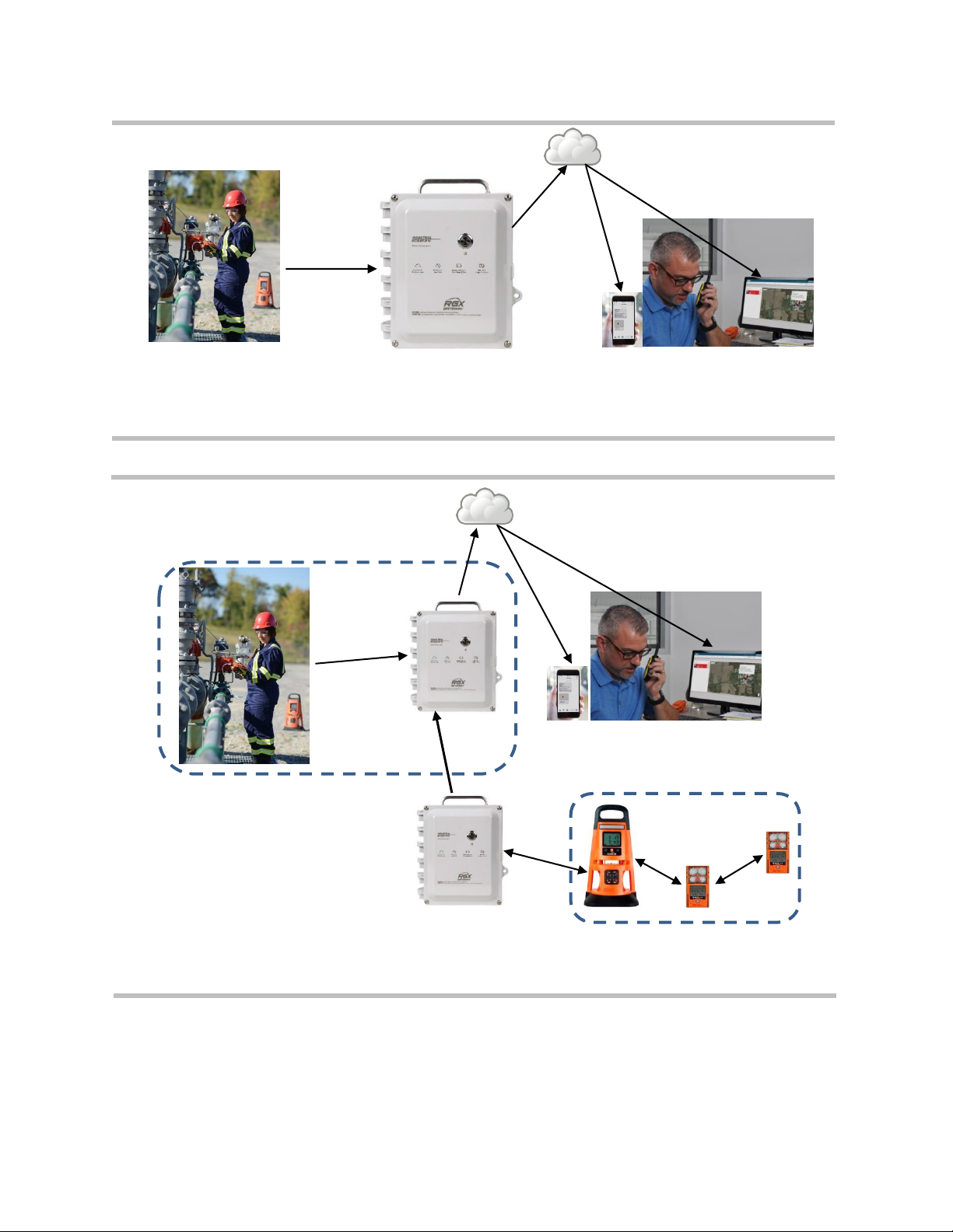
System Overview
LENS Wireless is a long-range, power-efficient wireless mesh network from Industrial Scientific. The
exchange of LENS group data supports the live-monitoring capabilities of iNet Now. From a computer or
smart-device, iNet Now users can learn, on a live basis, about everything from instrument gas readings to
gas alarms, man-down events, panic alarms, and more. An RGX operating in LENS repeater mode can fill
a distance gap or extend a LENS network. This wirelessly connected, live-monitoring system, as depicted
below, enhances the safety team's quick responses and preparedness for hazardous events.
2
iNet
Instrument data
RGX Gateway
iNet Now users
(live monitoring and real-time alerts)
Figure 1.1.A System overview
iNet
Main facility
RGX Gateway
iNet Now users
(live monitoring & real-time alerts)
RGX Gateway in
LENS repeater mode
extending the facility’s
LENS Wireless group
to another building.
RGX in LENS
repeater mode
Out building
Figure 1.1.B System overview with RGX in LENS repeater mode

3
Key Features
Table 1.1 Feature Comparison – RGX Gateway versus RGX in LENS repeater mode
Feature
RGX Gateway
RGX in LENS
repeater mode
Instrument to RGX communications
Yes
Yes
RGX to iNet communications
Yes
No
iAssign Beacon functionality
Yes
Yes
Always-on option
Yes
Yes
Transportable or mountable
Yes
Yes
Multiple power options
Yes
Yes
Indoor* or outdoor operation
Yes
Yes
*Indoor operation is suitable only when GPS location is not needed.
RGX Gateway
Communication
Instrument–RGX Gateway
LENS Wireless enables data sharing among wirelessly connected equipment items—gas-detection
instruments and RGX Gateway units—that are set to operate within a specified LENS group (e.g., Group
A). The following also apply.
• Ten named LENS groups are available.
• Each group can host up to 25 equipment items.
• More than one RGX can be included in a LENS group.
• RGX units operating in LENS repeater mode also use this network.
Instrument data exchanged through LENS are automatically encrypted with the Industrial Scientific key.
Optionally, a customer-supplied encryption key may be used.
RGX Gateway–iNet
The RGX can send data it receives from gas-detection instruments to iNet. These data take the form of
critical and noncritical events and you can set the data interval for each in iNet. The data interval is the time
between an event occurrence and the transmission of that event by the RGX.
Critical events: Set the interval value for critical events in iNet from 30 to 300 seconds.
Gas detection instruments
• Gas present, high-alarm
• Gas present, low-alarm
• Gas present, over-range (positive and negative) alarm
• TWA (time-weighted average) alarm
• STEL (short-term exposure limit) alarm
• LENS peer-instrument events (join, leave, lost, panic, and man-down)

4
RGX Gateway
• Gateway critical error
• Gateway online
• Gateway offline
Noncritical events: Set the interval value for noncritical events in iNet from 1 to 5 minutes.
Gas detection instruments
• Pump alarms
• Peer instrument system alarms
• Peer instrument calibration events
• Peer instrument sensor events
• Peer instrument battery events
• Peer instrument user-, site-name, and GPS updates
RGX Gateway
• GPS update
• Site name update
• Cellular signal strength updates
There are three transmission options for these RGX Gateway–iNet communications: wireless local area
network (wi-fi), cellular, and Ethernet. The customer sets each option to on or off, allowing the RGX to
maximize or to limit the number of channels through which it can exchange data with iNet. When more than
one transmission option is on, the customer prioritizes the order in which the unit will use them. For
example, if wi-fi and cellular are on, the unit can be set to first use wi-fi and if that is not available, use
cellular.
The RGX–iNet data exchanges are automatically encrypted using industry standard Transport Layer
Security (TLS 1.2).
Note: RGX Gateway–iNet communication does not apply to RGX units operating in LENS repeater mode.
Location
The RGX Gateway is suitable for indoor or outdoor use in locations that meet the product's certified uses
and specifications. Indoor operation is suitable only when a unit's GPS location is not needed.
iAssign Beacon functionality
The RGX can function as an iAssign® Beacon. You must specify a site name via iNet or the RGX
Configuration Interface. Beacon range and access-level can be set via iNet. When an instrument enters or
leaves the range assigned to the RGX, the Beacon signal it transmits can:
• Activate an instrument proximity alarm when the access level for an instrument’s current user
assignment is lower than the access-level setting assigned to the RGX.
• Change an instrument's site assignment.
Always-On
An RGX Gateway can be set for “always-on” operation in iNet. Use this feature to prevent manual
shutdown attempts in the field. Units operating in this mode cannot be shut down and will ignore manual
shutdown attempts until this mode is deactivated.

5
Mobility and mounting
The versatile RGX Gateway is designed for transportability and for permanent installation. It can be left
unmounted for mobile applications or mounted for permanent operation. The RGX features a durable,
factory-installed handle, which allows for ready relocation from site to site when mobility is a factor.
• The RGX can be transported in its optional case*, which provides added protection for the unit, allows
you to view the unit's operational status indicator, and access the unit's handle.
• Based on the application, the RGX can be surface mounted or mounted to a customer-supplied strut-
type rail installation using the optional Wall Mount Kit.
• The RGX can also be secured to a metal surface using the optional Magnet Mount Kit. IMPORTANT:
Do not use magnet mounts with a unit that will draw power from a fixed DC power source.
*ATEX-certified units ship with a required leather case. The case is available as an optional accessory for non-ATEX units.
Power
The RGX Gateway offers a variety of operational power options.
• The RGX can be powered solely by its rechargeable, factory-installed lithium-ion battery. This option is
well suited for short-term use conditions that allow for the unit to be situated, between use cycles, in a
nonhazardous location for charging.
• The RGX can receive operational power from a compatible, customer-supplied and customer-installed
fixed DC power source. This option is suitable for permanent installations.
• The RGX can receive operational power from a compatible power-supply accessory only from
Industrial Scientific; use of each accessory requires the RGX to be equipped with its Intrinsic Safety
(IS) Cable Adapter. This option is well suited for use conditions that do not require permanent
installation but demand a run time exceeding that of the factory-installed battery.
• In a nonhazardous location only, the RGX can draw operational power from its charging power supply.
Interior case access
The unit's case interior is accessed by removing four screws from the case lid. To help restrict access, the
case features tabs to accommodate a customer-supplied lock that is suitable for the location.
The unit features two conduit-hub openings, each sealed with a factory-installed plug. The conduit-hub
plugs should not be removed except for permanent installations that will make use of customer-supplied
conduit-hub fixtures as needed for the connection of a compatible fixed DC power source, Ethernet cable,
or both.
LENS repeater mode
The RGX Gateway can also operate in LENS repeater mode. RGX units operating in this mode connect
LENS group peers (instruments or RGX Gateways) to fill a distance gap or extend a LENS Wireless group.
Wireless connectivity among peers in the LENS group is maintained without any additional equipment.
• An RGX unit operating as a LENS repeater relays only its status; no LENS group data is sent to iNet
and no data is logged.
• Other RGX units within a LENS group can interact with and send instrument data to iNet.
Note: An RGX Gateway operating in LENS repeater mode can be upgraded to an RGX Gateway.

6
Compatibilities
Instruments
Use the information supplied below to ensure gas-detection instruments are compatible with the RGX
Gateway. As needed, upgrade instrument firmware to the required version, add LENS Wireless
functionality, and refer to the instrument's product manual.
Table 1.2 RGX Gateway compatible gas-detection equipment
Instrument
Required
firmware version
LENS Wireless
required
Industrial Scientific
Product Manual part
number
Ventis® Pro Series
V3.0 or higher
Yes
17156830
Radius® BZ1 Area Monitor
V3.0 or higher
Yes
17155915
Operational power sources
WARNING: The RGX offers these power-input options: 12 V Charger Port, IS Power Port, and 9–30 VDC
Terminal Block. When connecting external power, select only a single power-input type; connecting multiple
power inputs is not supported.
The RGX can draw operational power from its factory-installed rechargeable lithium-ion battery, which can
be charged in a nonhazardous location using the RGX charging power supply.
The operational run time for the factory-installed battery can be extended with the use of a compatible
power-supply accessory only from Industrial Scientific. Each power-supply accessory, as listed below, has
unique use restrictions or certified uses. Before using either accessory, read and understand its product
manual and control drawing 1810D9509-200, as represented by the schematic diagrams in Appendix A
of this manual. These schematics are also included in each power supply's Product Manual (part numbers
listed below).
Table 1.3 RGX compatible power-supply accessories
Power supply
Orderable part number
Product Manual
part number
Intrinsically Safe Extended Run Time Power Supplya
(ISERTPS), Intrinsic Safety (IS) Cable, and the RGX IS
Cable Adapter
18109516 (power supply)
17156261 (cable)
18109575 (adapter)
17158248
Extended Run Time Power Supplya (ERTPS) Kit
(includes IS Cable) and the RGX IS Cable Adapter
18109388-XAb (power-supply kit)
18109575 (adapter)
17158385
a
When used with the RGX Gateway, ensure a distance of 5 m (16 ' 4 ″) between the RGX and its power-supply accessory from Industrial
Scientific, or any that are in use nearby.
b
Where X indicates regional power-cord type (1 for NA, 2 for EU, 3 for AU, and 4 for UK).
The RGX Gateway's input power parameters are listed below.

7
Table 1.4 RGX Gateway intrinsic safety (IS) input parameters
Item
Value
Ui
16.2 VDC
Ii
0.980 A
Pi
2.2 W
Ci
0 µF
Li
0 mH
The RGX Gateway can be operated using customer-supplied, customer-installed fixed DC power that
supplies a compatible input voltage range of 9–30 VDC with a maximum current of 5.0A connected to the
dedicated ports on the RGX terminal block. Before connecting power, read and understand control drawing
1810D9509-200, as represented by the schematic diagrams in Appendix A of this manual.
The charging power supply and power cord (part number 17158665) can be used to provide operational
power to the unit only when the unit is operated in a nonhazardous location.
Specifications
RGX Gateway specifications
Ensure all aspects of installation and operation are consistent with the product specifications listed below.

8
Table 1.5 RGX Gateway specifications
Item
Description
Power input
Three mutually exclusive options:
• Terminal block: 9–30 VDC, 5.0A (Hazardous Locations)
• 12V power supply: 12VDC, 5.0A (Nonhazardous Locations Only)
• IS power: 16.2 VDC, 0.980A
Size (length x width x depth)
28 cm x 23 cm x 15 cm (11 ″ x 9 ″ x 6 ″)
Weight
2.5 kg (5.6 lb)
Case materials
Polycarbonate
Ingress protection
IP64 (outdoor use)
Wet location rated
Yes
Environmental rating
Type 1
Pollution degree
2
Overvoltage category
≤60 volts
External buttons and indicators
Buttons
One; power button on case lid
Indicators
Two
• Power-button light (colors and patterns indicate operational status)
• Indicator light on side panel (indicates battery charging status)
Internal buttons and indicators
Buttons
One; SW1 RESET (resets the unit to its original factory-setting values)
Status indicators
Four
• COMM indicates communication status.
• LENS indicates LENS Wireless status.
• ERR2 indicates communication error.
• ERR1 indicates system error.
Ethernet indicators
Two
• Yellow indicates connection status.
• Green indicates connection speed.
Operating conditions
Ambient temperature
–20 °C to +55 °C (–4 °F to +131 °F)
Humidity
5−95% relative humidity (RH) noncondensing (continuous)
Altitude
Use only at altitudes below 2000 m (6560 ')
Storage conditionsa
Temperature
–40 °C to +70°C (–40 °F to +158 °F)
a
When a unit is stored for more than 30 consecutive days, fully charge the battery before powering on the unit.

9
Battery specifications
Run time, operating temperature, and other specifications for the factory-installed battery are listed below.
Table 1.6 RGX Gateway factory-installed battery specifications
Item
Value
Battery type
Rechargeable lithium-ion
Run timea
168 hours
Battery charge timeb
up to 8 hours
Charging cycles
up to 1500 cycles minimum
Charging temperature rangec
5−45°C (41−113°F)
Nominal voltage
3.65 VDC
Nominal capacity
16.80 Ah (61.32 Wh)
a
Approximate run time when all of the following statements are true. The RGX battery is new and fully charged. The RGX is operating at room temperature (25
°C [77 °F]) using any or all communication options. The GPS setting is on and set to send location data every 60 minutes. The LENS group includes up to 25
equipment items. The RGX transmits up to 60 minutes of alarm data every 24 hours and is set to upload noncritical data every five minutes.
b
When charged at room temperature (25°C [73 °F]).
c
Battery charging is suspended in temperatures below 5 °C (41 °F) and above 45 °C (113 °F).
Power-supply accessory run-time effects
The RGX Gateway can draw operational power from compatible power-supply accessories only from
Industrial Scientific. The RGX can run indefinitely on either the Intrinsically Safe Extended Run Time Power
Supply (ISERTPS), Industrial Scientific Product Manual part number 17158248, or the Extended Run Time
Power Supply (ERTPS), Industrial Scientific Product Manual part number 17158385.
Each power-supply accessory has its own use restrictions. Refer to an accessory's Product Manual to
determine if the power supply suits the application and is used in accordance with manual
recommendations.
Hardware Overview
The main hardware components of the RGX Gateway are identified below in Figure 1.2.A and Figure 1.2.B
(exterior and interior, respectively).

10
Case lid
Case base
Fastener (4x);
1.69 N m; 240 oz in screw torque
Handle
Hinge
Screw hole (4x); for use with
optional Wall Mount kit or
Magnet Mount kit
Power button
Indicator light (system-power-
communication status)
Indicator light quick
referencea
NFC target
Labels
MAC addresses (on label)
Side (left)
Side (right)
Indicator light
(charging status)
Serial number (S/N)
Intrinsic safety (IS) power
port and tethered cap
Charging power supply port
and tethered cap
Vent
Tether-chain screw
Lock tabs (for use with
customer-supplied item)
Activation code
Top
Bottom
Handle
Conduit-hub plug (2x); each
covers a hole size of 27.8 mm
(1.09 ″)
Figure 1.2.A Hardware overview (exterior)
a
Depicts key connectivity and power light indicators. For a complete list of indicator light patterns and their meanings, see Table 3.6 Power-
button light indicators.

11
Vent nut (behind vent)
Power-button assembly
Battery
Conduit-hub plug (2x)
Factory reset buttona
Protective plastic cover
Indicator lights
(from top to bottom: COMM,
LENS, ERR2, and ERR1)
Wire and cable guides (4x)
RJ45 port
(for use with customer-supplied
Ethernet cable)
Terminal blockb
Terminal blockb
GND
PWR IN 9V–30V (9–30 VDC
with 5.0A maximum current)
Figure 1.2.B Hardware overview (interior)
a
When the factory reset button is pressed and held for approximately 20 seconds, the unit’s settings will revert to the original factory-setting
values. After a reset, adjust unit settings as needed.
b
For use with customer-supplied, customer-installed fixed DC power that supplies a compatible input voltage range of 9–30 VDC with a
maximum current of 5.0A connected to the dedicated ports on the RGX terminal block.


Chapter 2 2
Deployment Planning
Introduction
Communications
Settings and Connections
Introduction
Whether you are using a single RGX™ Gateway or multiple units, this chapter will help you make decisions
about how each will operate within your organization. An RGX Gateway operating in LENS™ repeater
mode connects LENS group peers (instruments and RGX Gateways) maintaining wireless connectivity
among peers without any additional networking equipment. Strategic placement of an RGX operating in
LENS repeater mode can fill a distance gap or extend a LENS Wireless group.
Communications
The RGX communicates using two distinct wireless networks. One network allows the RGX to
communicate with gas-detection instruments, other RGX Units, and RGX units operating in LENS repeater
mode. RGX units operating in this mode only communicate using this network. The other network allows
the RGX to send instrument data to iNet®, which supports the live-monitoring capabilities of iNet Now. Both
networks are described below.
RGX Gateway−instrument communication (LENS Wireless)
The RGX can communicate with gas-detection instruments only when the equipment items are set to
operate in the same named LENS Wireless group, and other requirements (settings and connections) are
met. The following apply to or should be decided for deployment planning and setup preparation.
• Decide in which named LENS group (e.g. "Group A") the RGX will operate.
• A LENS group consists of gas-detection instruments, RGX Gateway units, and optionally RGX units
operating in LENS repeater mode, including up to 25 items.
• More than one RGX unit can be set to operate in a single LENS Group.
• Decide whether any RGX units operating in LENS repeater mode will be needed to bridge a gap or
extend a LENS group.

14
RGX Gateway–iNet communication
The RGX Gateway is set, by the customer, to communicate with iNet using one or more options—wi-fi,
cellular, and Ethernet. The options you can select may be limited by your company's communication
preferences and security guidelines. See your network administrator if you are not familiar with your
company's communication protocols. For deployment planning and setup preparation, determine the
following.
• Decide which of the three communication options a unit will use.
• If a unit will use more than one of these options, decide the priority order in which they will be used. For
example, if both wi-fi and cellular will be used, a unit can be set to first use wi-fi and if that is not
available, use cellular.
• If a unit will use Ethernet or wi-fi determine the type of "network protocol" connection it will use—
dynamic (a.k.a., DHCP or Dynamic Host Configuration Protocol) or static. If this setting is unknown to
you, contact your network administrator.
Wireless Settings and Connections
The settings itemized in Table 2.1 are required for iNet Now live monitoring of LENS group peers.
Table 2.1 Required equipment settings for iNet Now live monitoring
Equipment items
Setting item
RGX Gatewaya
Ventis Pro
Radius BZ1
LENS Wireless
No setting required
Menu: Wireless
Setting: LENS Wireless
Value: iNet Now and Local
Menu: Wireless
Setting: Wireless Radio
Value: iNet Now and Local
LENS Wireless Groupb
Menu: LENS Wireless
Setting: LENS Group
Value: Group Xc
Menu: Wireless
Setting: LENS Wireless,
LENS Group
Value: Group Xc
Menu: Wireless
Setting: Group
Value: Group Xc
Encryption keya
Menu: LENS Wireless
Setting: Encryption Key
Valuedd: Automatic or custom
Menu: Wireless
Setting: LENS Wireless,
Encryption
Valued: Automatic or custom
Menu: Wireless
Setting: Encryption
Valued: Default or custom
a
Also applies to RGX units operating in LENS repeater mode.
b
All equipment items must be set to the same LENS Wireless group and encryption key.
c
"X" is used here to indicate the value will be a single character in length; the available values are the letters A through J.
d
"Default" sets the unit's LENS Wireless to the Industrial Scientific encryption key, and "custom" to the customer's key. If a custom key will
be used, some setup is also required in iNet.

15
You will need to make decisions about the RGX GPS and noncritical data settings.
• Determine if the unit will operate with its GPS on or off. When on, the unit can acquire its GPS
coordinates and send this location data to iNet. Importantly, the GPS data are used by iNet Now users
to identify the location of an RGX that has sent data from an in-alarm gas detector. Location data are
also useful for tracking units that will be transported among sites. If the unit's GPS will be on, determine
the interval (1–60 minutes) at which the unit will send its location data to iNet.
• Determine the interval (minutes) at which the unit will send its noncritical data to iNet to support the
live-monitoring capabilities of iNet Now.
• When setting intervals, consider the application. For example, while a longer interval for sending GPS
data uses less battery power, a shorter interval may be better suited if the RGX will be frequently
moved among sites.
Connections are generally maintained, when no interference is present, by keeping the equipment items
within their range guidelines (see Table 2.2 below). Provided the required LENS Wireless connections are
maintained, the live-monitoring of equipment items accommodates worker and equipment movement.
Table 2.2 Range guidelines to maintain LENS Wireless connections
Line-of -sight distance, maximum
LENS Power Mode Setting
Equipment items
World setting
CE REDb setting
RGX to equipment items
RGX to RGX
a
(World)
—
300 m (328 yd)
185 m (202 yd)
RGX to RGX
a
(CE RED)
—
185 m (202 yd)
185 m (202 yd)
RGX to Ventis Pro
100 m (109 yd)
—
—
RGX to Radius BZ1
—
300 m (328 yd)
185 m (202 yd) c
Instrument to instrument
Ventis Pro to Ventis Pro
100 m (109 yd)b
—
—
Ventis Pro to Radius BZ1
100 m (109 yd)b
—
—
Radius BZ1 to Radius BZ1
300 m (328 yd)
185 m (202 yd) c
a
Also applies to RGX units operating in LENS repeater mode: RGX to LENS repeater, LENS repeater to LENS repeater, and LENS
repeater to RGX.
b
For more information see EU Radio Equipment Directive in the front matter of this manual.
c
Applies when the equipment items face each other.
To learn more about the Ventis Pro® or the Radius® BZ1, consult its product manual.


Chapter 3 3
Setup
Introduction
Unpacking
Activation
Charging the battery
Power On and Shutdown
Configuration
Installation Precheck
Introduction
Only qualified personnel should setup the RGX™ Gateway.
Choose a setup area in a nonhazardous location with a clean, uncluttered surface on which to work.
Ensure that a power source compatible with the unit's charging power supply cord is present.
Additional setup needs will be listed throughout this chapter. Needs will vary based on a unit’s intended
placement, operational power source, communication settings, and other factors.
Unpacking
During the unpacking process, account for and examine each ordered item. If any item is missing or
appears to have been damaged, contact Industrial Scientific or an authorized distributor of Industrial
Scientific products. After unpacking, peel the protective plastic film from the case lid.
Table 3.1 Package contents
Quantity
Item
Description
As ordered
As ordered
RGX Gateway
or
RGX Gateway operating in LENS repeater
mode
Transmits data between compatible, enabled Industrial
Scientific gas-detection instruments and iNet.
Extends the range of a LENS group but does not transmit
any instrument data or events to iNet.
As ordered
Charging power supply and power cord
12 VDC power supply with customer-ordered cord that fits
one power source type (AUS, EU, NA, or UK).
1
Document
Warnings and Cautionary Statements

18
The values noted below, unique to each RGX, are required for setup.
Side (right)
Case base
Serial number (S/N)
Required for unit activation.
Activation code
Required for unit activation.
MAC addresses (on label)
Required for Ethernet configuration and permanent
installations.
IP Address
Note: If the value is unknown to you, see your
network administrator who may need the unit's MAC
address. For some tasks, a default static IP is
supplied.
User name
The default value is RGXadmin (case sensitive).
Figure 3.1 Required setup values
Activation
RGX Gateway
Log into iNet® and follow this navigation.
• Click on the Equipment tab.
• Choose Activate New Equipment.
• In the appropriate fields, enter the unit's Serial Number and Activation Code.
• Use the OK button to submit the information.
Note: When an RGX has not yet been activated, or when deactivated, the power button light will slowly blink red. See Table 3.6
Power-button light indicators for more information. In this state the RGX cannot connect to iNet to relay instrument events.
Gas-detection instruments
To transmit gas-detection instrument data wirelessly from instrument to RGX to iNet and onto the users of
iNet Now, the instruments must be activated for live monitoring. The following are required.
• Access to iNet.
• The Serial Number (S/N) for each instrument to be monitored.
Log into iNet and follow this navigation.
• Click on the iNet Now tab.
• Choose iNet Now Activations.
• Use the serial number search box to locate an instrument.
• An item’s Activated check-mark box indicates an instrument is activated for live monitoring.

19
Charging the battery
Using only the supplied RGX charging power supply and power cord, charge the unit's installed battery as
shown and described below.
Nonhazardous location
Charging power supply port
Indicator light (charging
status)
Charging power supply and
power cord
─
Connect the charging power
supply to its power cord.
Uncap the unit's charging
power supply port: turn the
port cap counterclockwise to
expose the port for use.
Connect the power-supply cable to the port and turn its
swivel cover clockwise (approximately 45°) until it clicks
closed or a full-stop connection feedback is felt.
Plug the power cord into a compatible outlet.
─
Check the unit's charging-status indicator light.
• The green light will first blink on and off to indicate a
precharging state.
• The green light will stay on, but stop blinking, to indicate
charging is in progress.
• The light will turn off to indicate the battery is fully
charged.
When the battery is fully
charged, unplug the power
cord from the outlet.
Disconnect the cable from
the port: turn its swivel cover
counterclockwise
(approximately 45°).
Cap the charging power
supply port: turn its swivel
cover clockwise
(approximately 45°) until it
clicks closed or a full-stop
connection feedback is felt.
Note: always cap a port
when it is not in use.
Figure 3.2 Charging the battery

20
Power On and Shutdown
Locate the power button on the case lid.
Power on
Press the power button for approximately 5 seconds until the power-button light turns on.
• If the unit is fully operational, the power-button light will be solid (not blinking) green.
• For information about other light patterns and colors, see Table 3.6 Power-button light indicators.
Shutdown
Press the power button for approximately 7 seconds.
• When the power-button light starts to blink, release the button.
• To indicate unit shutdown is in progress, the light will blink red and green.
• To indicate the unit is fully shutdown, the light will turn off.
Note: An RGX Gateway set for “always-on” operation cannot be manually shut down and will ignore manual
shutdown attempts until this is deactivated via iNet.
Configuration
RGX configuration requires the use of one or two "apps", the RGX Configuration Interface (Interface) and
iNet software. Generally, as outlined below, the Interface is used to configure RGX-to-iNet communication
settings; iNet software is used for all other RGX settings (see below). After initial configuration, use each
app as needed to edit the settings it supports.
Table 3.2 Configuration applications
App
RGX Configuration
Interface
iNet software
Supported settings
Always-on functionality
No
Yes
iAssign Beacon (access level and range)
No
Yes
LENS repeater mode
No
Yes
LENS Wireless (group and encryption key)
No
Yes
RGX-iNet communication (cellular, wi-fi, and
Ethernet)
Yes
No
Site name (also serves as Beacon site name)
Yes
Yes
Other (GPS, data upload intervals, communication
priority, etc.)
No
Yes
Accessing and using the RGX Configuration Interface app
If the unit's communication setting will be cellular only, then you do not need to access or complete any
work in the RGX Configuration Interface; skip to Figure 3.5 iNet settings.

21
There are two methods for accessing the RGX Configuration Interface—through a wi-fi or Ethernet
connection. Supplies required for each access method are listed below.
Table 3.3 Supplies needed for configuration
Access method
Item
Wi-fi
Ethernet
Torx screwdriver with a T25 bit
No
Yes
Ethernet cable Cat5 or greater
No
Yes
Computer (with browser)
No
Yes
Smart device (with browser)
Yes (or computer)
No
RGX Serial Number (S/N)
Yes
Yes
Access to iNet
Yes
Yes
When using the RGX Configuration Interface, the following apply.
• If you are not familiar with your company's communication protocols, see your network administrator for
assistance.*
• If your company’s wireless network uses “WPA2-Enterprise” security, the RGX Interface will require the
upload of a certificate of authenticity that is 2048-bit or less and supplies the full chain of trust.*
• As with most applications, the Interface is subject to timing out when idle.
• When a data field appears in gray, no entry is required.
• Within each section, work from top to bottom.
• When a "test" button appears, use it after entering all the required values that precede it; then, follow
any on-screen instruction to learn of and correct for any invalid or missing values.
*These items do not apply to an RGX Gateway operating in LENS repeater mode.
Based on your access method, wi-fi or Ethernet, complete only one of two possible instruction sets as
indicated below.
Table 3.4 RGX Configuration Interface instruction sets by access method
Instruction set
Figure 3.3
Figure 3.4
Access Method
Wi-fi
Yes
No
Ethernet
No
Yes

22
Figure 3.3
1
Power on the RGX
On the case lid, press the power button for approximately 5 seconds until the power-button light turns
on. Observe the power-button light and proceed as noted below.
Green only (blinking or solid)
Continue.
Includes red (blinking or solid)
See Table 3.6 Power-button light indicators before continuing.
Light does not turn on
Try again. If the condition persists, the unit may not have
sufficient charge. Charge the unit before continuing.
2
Activate Wi-fi access mode
Tap the power button three times quickly. If the power-button light blinks red, continue; otherwise, try
again.
3
Log into the RGX Configuration Interface
Check the smart device for a list of detected wi-fi devices:
• Locate the serial number for the unit; highlight it and click on it.
• When prompted to enter a security key, enter 0 (zero) followed by the RGX’s activation code.
On the smart device, open a browser:
• In the browser address bar enter https:// followed by the RGX IP address.
• If the IP address is unknown, enter: 192.168.1.1
When prompted, enter the log-in credentials below to access the RGX Configuration Interface:
• User name: RGXadmin (case sensitive)
• Password: Unit activation code
Note: It is recommended that the password be changed after initial log in. The case-sensitive
password requirements follow.
Use a minimum of 8 characters in any order, including minimally, at least:
• one number
• one lowercase letter
• one uppercase letter
• one symbol from this set: () ` ~ ! @ # $ % ^ & * - + = | \ { } [ ] : ; " ' < > , . ? /
4
Configure options
Access Settings
RGX Gateway only
• Review the RGX–iNet communications options: cellular, wi-fi, and Ethernet. Enable or disable
each option.
• For each enabled option, enter, select, or edit the required values.
Reminder: If your company’s wireless network uses “WPA2-Enterprise” security, the RGX
Interface will require the upload of a certificate of authenticity that is 2048-bit or less and
supplies the full chain of trust.

23
RGX Gateway operating in LENS repeater mode
Site name can be set. All other settings must be edited in iNet.
Save and Reboot
When finished, click save; the Interface will prompt you to confirm the save.
When prompted to reboot, click on the prompt, then confirm. No other action is needed, the software
will complete the reboot.
5
Verify RGX Gateway operation
To verify the unit is operational, observe the power-button light. If it is green and not blinking, the unit
is operational. For information about other indicator-light patterns and colors, see Table 3.6 Power-
button light indicators.
Next go to Figure 3.5 and follow the instructions to use iNet, where you will complete all other
settings.
Figure 3.3 Wi-fi access method for RGX Configuration Interface
Figure 3.4
1
Shut down the RGX
Set the unit on the work surface, case lid facing up.
Observe the power-button light.
• If the light is off, continue.
• If the light is on and green only (blinking or solid), shut down the
unit. Press the power button for approximately 7 seconds; when its
light starts blinking, release the button. The power-button light will
blink red and green to indicate shutdown is in progress; it will turn
off to indicate the unit is fully shutdown.
• If the light is on and includes red light (blinking or solid), see Table
3.6 Power-button light indicators before continuing.
2
Access unit interior
Using a torx screwdriver with a T25 bit, unscrew and remove the four
screws that secure the case lid to the case base.
Set aside the screws for later reinstallation.
The case is hinged on the left; open its lid from right to left.

24
3
Connect Ethernet cable; power on unit
Before connecting the Ethernet cable, you will need to ensure the
computer and the RGX are on the same network. Consult your network
administrator for assistance. Note: For network connections, the default
static IP is 192.168.1.1.
Next, connect one end of the customer-supplied Ethernet cable (Cat5 or
greater) to the computer, then connect the other end to the Ethernet
port.
Power on the RGX: On the case lid, press the power button for
approximately 5 seconds. Observe the power-button light and proceed
as noted below.
Green only (blinking or solid)
Continue.
Includes red (blinking or solid)
See Table 3.6 Power-button light
indicators before continuing.
Light does not turn on
Try again; be sure to hold the power
button for a full 5-second count. If
the condition persists, the unit may
not have sufficient charge. Charge
the unit before continuing.
4
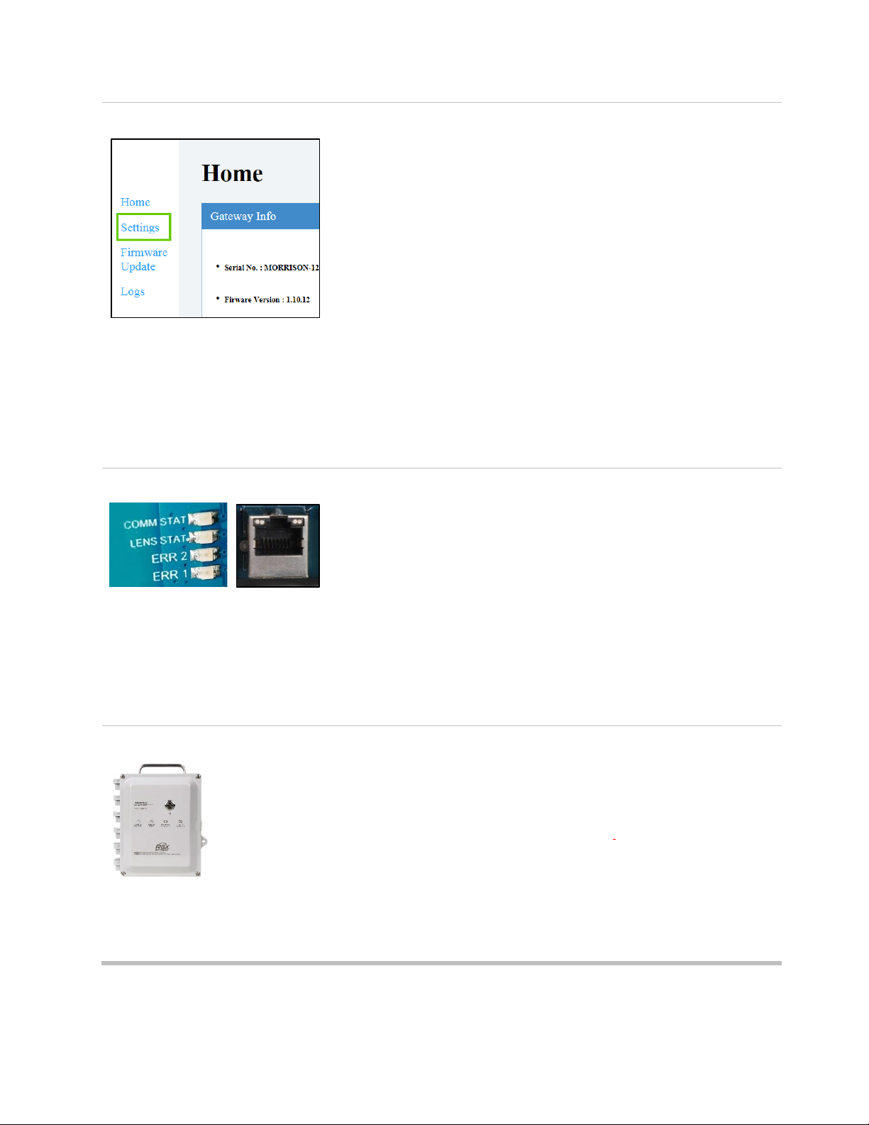
Observe interior LEDs*
Observe the interior LEDs located near the left edge of the PCB (printed
circuit board). From top to bottom, they are labeled COMM STAT, LENS
STAT, ERR2, and ERR1. Each light may be on or off.
Check the ERR2 light (third from top). At this point, it may be red;
continue.
*Note: If operating on battery power only, the interior LEDs will not be on.
5
Log into the RGX Configuration Interface
On the computer, open a browser;
• In the address bar enter https:// followed by the RGX IP address.
• If the IP address is unknown, enter: 192.168.1.1
When prompted, enter the log-in credentials below to access the RGX
Configuration Interface:
• User name: RGXadmin (case sensitive)
• Password: Unit activation code
Note: It is recommended that the password be changed after initial log
in. The case-sensitive password requirements follow.
Use a minimum of 8 characters in any order, including minimally, at
least:
• one number
• one lowercase letter
• one uppercase letter
• one symbol from this set: () ` ~ ! @ # $ % ^ & * - + = | \ { } [ ] : ; " ' <
> , . ? /
25
6
Configure options
Access Settings
RGX Gateway only
• Review the RGX–iNet communications options: cellular, wi-fi, and
Ethernet. Enable or disable each option.
• For each enabled option, enter, select, or edit the required values.
Reminder: If your company’s wireless network uses “WPA2-Enterprise”
security, the RGX Interface will require the upload of a certificate of
authenticity that is 2048-bit or less and supplies the full chain of trust.
RGX Gateway operating in LENS repeater mode
Site name can be set. All other settings must be edited in iNet.
Save and Reboot
When finished, click save; the Interface will prompt you to confirm the
save.
When prompted to reboot, click on the prompt, then confirm. No other
action is needed, the software will complete the reboot.
7
Status check
Observe the LEDs* inside the case and compare them to the
"operational status" column in Table 3.5 below.
• The LENS Wireless status light will be off until another equipment
item joins the LENS group; otherwise, if there are no errors or
connection issues, disconnect the Ethernet cable from the unit.
• If there are errors or issues, recheck the work completed to this
point. If an issue persists, contact Industrial Scientific.
• Disconnect the cable from the computer and, as needed,
reconfigure the computer to the desired network.
*Note: If operating on battery power only, the interior LEDs will not be on.
8
Close case lid and secure to case base
Close the case lid and ensure all wires and cables are:
• secure
• contained entirely inside the case
• away from the unit’s closure surfaces.
Reinstall the four fasteners with the T25 torx bit to secure the case lid to
the case base. Screw torque: 1.69 Nm (240 oz in)
Go to Figure 3.5 and follow the instructions to use iNet where you will
complete all other RGX settings.
Figure 3.4 Ethernet access method for RGX Configuration Interface

26
Table 3.5 Internal indicator lights* and their meanings
Label
Indicator
Light
Operational status
COMM STAT
iNet connection status
Green
The unit has a connection to iNet; if
blinking green, data are being
exchanged.
Off
The unit has no connection to iNet.
LENS STAT
LENS Wireless status
Green
LENS Wireless is operational; if blinking
green, data are being exchanged.
Off
Either LENS Wireless is not operational
or no other equipment items are in the
LENS group.
ERR2
Communication status
Red
There is a communications error.
Off
There is no communications error.
ERR1
System status
Red
There is a system error.
Off
There is no system error.
Ethernet cable port
Left LED
Ethernet connection
status
Green
There is no Ethernet connection.
Off
There is an Ethernet connection.
Right LED
Ethernet connection
speed
Yellow
The Ethernet connection is 10 Mb.
Off
The Ethernet connection is 100 Mb.
*Note: To conserve battery power, the interior LEDs will not be on if operating on battery power only. Connect to an external power input to
check the LED status indicator lights.

27
1
Log into iNet
Follow this navigation.
• Click on the Equipment menu.
• Choose Equipment List.
At the equipment list page (not shown), use the search box associated with the
Serial Number column to enter the unit's serial number.
Click on the unit's serial number; the unit's information will display.
2
Configure LENS Wireless and General settings
Go to settings.
• Use the Quick-links box (shown) or
• Scroll the page to Options, click on Edit
In the LENS Wireless and General sections, complete these settings.
• GPS
a
• noncritical data interval
a
• communication priorities
• LENS group name
• LENS group encryption key
• Always-on / Disable Shutdown
b
• iAssign Beacon settings:
o BLE Range Access: 1m (3.3 ft), 5m (16.4 ft), 20m (65.6 ft), or 30 m
(98.4 ft)
o Restriction Access Level
c
– Set the access level for the Beacon.
Note: The site name can be edited under Sites.
a
When setting intervals, consider the application. For example, while a longer
interval for sending the unit's GPS data uses less battery power, a shorter interval
may be better suited if the unit is to be frequently moved among sites.
b
An RGX Gateway set for “always-on” operation cannot be manually shut down
and will ignore manual shutdown attempts until this mode is deactivated via iNet.
c
When an instrument enters or leaves the Beacon range assigned to the RGX and
the access level for the instrument’s user assignment is lower than the accesslevel setting assigned to the RGX this could cause an instrument proximity alarm.
3
If the gas-detection instruments have not yet been activated for live monitoring,
follow this navigation.
• Click on the iNet Now tab.
• Choose iNet Now Activations.
Use the serial number search box to locate an instrument. A check mark in the
Activated column indicates an instrument is activated for live monitoring.
Figure 3.5 iNet settings

28
Installation Precheck
Power on the unit if it is not already on. Observe the power-button light on the case lid and compare it to
the "operational status" column in Table 3.6 below.
• If there are no errors or issues, shut down the unit.
• If there are any issues, recheck the work completed to this point. If an issue persists, contact Industrial
Scientific.
Table 3.6 Power-button light indicators
Color and state
Operational status
Green only
Solid (not blinking)
The unit is operational.
Rapid blinking
The unit is trying to communicate with iNet.
Slow blinking
Very slow blinking
(once every 4 seconds)
The unit is communicating with iNet but its GPS* is not working.
or
The unit cannot communicate with iNet.
RGX is set to LENS repeater mode.
Both green and red
Alternating
Low battery warning
or
The power button has been pressed and the unit is shutting down.
Red only
Solid (not blinking)
The unit is not operational because there is no power.
Rapid blinking
Indicates that wi-fi access mode has been activated
Slow blinking
Indicates that the unit is inactive (never activated or currently
deactivated), See also Activation for more information.
or
An error has occurred that requires resolution. Power off, then
power on the unit. If the issue persists, contact Industrial Scientific
Light is off
The unit is powered off or the battery is completely discharged.
*Status is indicated only when feature is enabled.

Chapter 4 4
Installation and Operation
Introduction
Site Selection
Placement and Mounting
Installation Preparation
Installation
Operation Precheck
Introduction
Only qualified personnel should install and operate the RGX™ Gateway.
To help prevent injury and damage to the equipment, handle the unit with care and avoid dropping it.
NOTICE: A customer's intended use of the RGX may require mounting, as well as the installation of a
compatible fixed DC power source, an Ethernet connection, or both. These and other tasks will require the
customer acquisition and use of equipment, tools, and services. All customer-supplied equipment, tools,
and services required to install (or uninstall), mount, or otherwise secure (or remove) the unit must comply
with and be used in ways that meet any restrictions imposed by the hazardous-classified area; local, state,
or national codes, regulations, standards, permits, or other requirements; and the Authority Having
Jurisdiction (AHJ). The wiring of intrinsically safe circuits follows these examples.
• NFPA 70 National Electric Code (NEC); Article 504
• CSA C22.1 Canadian Electric Code (CEC); Appendix J 18-152
• IEC/EN 60079-14 Electrical installations
CAUTION: RGX Gateway for use in hazardous locations only as to intrinsic safety per control drawing
1810D9509-200.
AVERTISSEMENT: RGX Gateway pour une utilisation dans des emplacements dangereux uniquement en
ce qui concerne la sécurité intrinsèque par schéma de commande 1810D9509-200.
A list of possible customer-supplied equipment items and services is provided below.

30
Table 4.1 Customer-supplied equipment and services
Item
Purpose
Restrictionsa
Mounting (optional)
Mounting surface and
mounting equipment items
Mounting the unit for
operation.
The mounting surface must support 10.9 kg (24 lb) static
weight and must meet any weight-bearing requirements
of the customer-supplied mounting equipment.
A strut-type kit or strut-type rails and fasteners for
mounting are suitable for a permanent installation. A unit
can also be surface mounted.
Wall Mount Kit from Industrial
Scientific
For use with surface mounting
or strut-type mounting
See the Service section of this manual for instructions.
Note: The kit includes a label that replicates important
information printed on the back of the RGX, including the
LAN MAC and WAN MAC values. Copy these two values
onto the kit label in the designated spaces. Affix the label
to an area of the unit that will be visible during operation.
Magnet Mount Kit from
Industrial Scientific
For use with metal surface
mounting
Do not use with units that will draw power from a fixed DC
power source.
See the Service section of this manual for instructions.
Power source, external (optional)
Fixed DC power source
Operational power suitable for
permanent installations.
9–30 VDC with a maximum current of 5.0A.
Hubs and conduits suitable for the application and hole
size 27.8 mm (1.09 ″).
ISERTPSb from Industrial
Scientific
Operational power suitable for
extended run-time
installations.
Before using the ISERTPS, ensure your application
meets the product's certified uses and restrictions: read
and understand the ISERTPS Product Manual (part
number 17158248).
ERTPSb from Industrial
Scientific
Operational power suitable for
extended run-time
installations.
Before using the ERTPS, ensure it suits your application:
read and understand its Product Manual (part number
17158385). Note: Except for its IS cable, the ERTPS is
not certified for use in any hazardous-classified areas.
Supplies (optional)
Torx screwdriver set with T20,
T25, and T30 bits
Removal or installation of
conduit-hub plugs (T20
screwdriver and 3/8 ″ wrench),
wall mounts (T30), and case
fasteners (T25)
Suitable for the installation location.
3/8 ″ open-end wrench
Other (optional)
Ethernet cable (if needed, 90°
adapter or short adapter
cable)
Required only for units that
will use Ethernet during
operation.
Cat5 (or greater) Ethernet cable, terminating in RJ45
modular connectors, that supports 10/100 Ethernet. For
longer cables, 14−110 m [46–360 '], use a solid
conductor shielded twisted pair cable. To prevent
damage to the Ethernet cable and the RGX, it is
recommended that the Ethernet cable have either no
strain relief or flexible strain relief; if needed, a 90°
adapter or short adapter cable may be used.

31
Table 4.1 Customer-supplied equipment and services
Item
Purpose
Restrictionsa
Lock
Restricts access to the unit's
interior.
Suitable for the installation location.
a
All customer-supplied equipment, tools, and services must comply with and be used in ways that meet any restrictions imposed by the
hazardous-classified area; local, state, or national codes, regulations, standards, permits, or other requirements; and the AHJ.
b
Ensure a minimum distance of 5 m (16 ' 4 ″) between a unit and its optional power-supply accessory from Industrial Scientific, or any that
are in use nearby.
Site Selection
Choose an operational location (site) that complies with the product's certified use restrictions and product
specifications. Ensure that the site also supports the following.
• The unit is hinged on its left side and opens from right to left. Avoid locations that block this movement.
• If the RGX Gateway will be used with a power-supply accessory from Industrial Scientific (ISERTPS or
ERTPS), ensure that the site allows sufficient space for the RGX and its Intrinsic Safety (IS) Cable
Adapter, which extends 62.2 cm (24.5 ″) from the IS power port on the left side of the unit. Ensure that
the ISERTPS or ERTPS is installed and used in accordance with the instructions provided in the
respective product manual.
• If an ISERTPS or ERTPS power-supply accessory will be used, maintain a minimum distance of 5 m
(16 ' 4 ″) between the RGX and the accessory or any nearby ISERTPS or ERTPS accessories (see
Figure 4.1 below). This allows the RGX to operate in a manner designed to prevent radio frequency
interference per FCC (Federal Communications Commission) requirements.
• If the RGX will be connected to a compatible customer-supplied, customer-installed fixed DC power
source, Ethernet cable, or both, ensure that the site will accommodate conduit of the required length.
• To improve wireless performance (wi-fi and LENS™ Wireless), ensure that placement or installation of
the RGX allows for a minimum distance of 1 m (3 ' 3 ″) between the bottom of the unit and the ground.
• If the unit will use cellular, wi-fi, or both of these communication methods, ensure that the site meets
any connection-range requirements of those services and is not shielded.
• To optimize performance for a unit that will use GPS, cellular communication, or both, ensure that the
site provides ample open-sky access and allows the unit to be mounted or placed using a vertical
orientation, its handle toward the sky. IMPORTANT: Units used in an indoor environment cannot
receive the signal required for GPS functionality.
• Ensure that the unit and any cable or cord connections are situated away from standing water.

32
ISERTPSa
RGX Gateway
b
5 m (16 ' 4 ″)
1 m (3 ' 3″)
Ground
Figure 4.1 Distance requirements: RGX-to-power-supply and RGX-to-ground
a
ISERTPS shown, also applies to ERTPS.
b
Also applies to an RGX Gateway operating in LENS repeater mode.
Placement and Mounting
The unit can be placed or mounted for operation.
The optional Wall Mount Kit can be used for a unit that will be mounted to a wall, another surface, or to a
strut-type rail setup. The kit contains a label that replicates important information printed on the back of the
RGX, including the LAN MAC and WAN MAC values. Copy these two values onto the kit label in the
designated spaces. Affix the label to an area of the unit that will be visible during operation.
The optional Magnet Mount Kit is used to mount the unit to a metal surface. IMPORTANT: Do not use the
Magnet Mount Kit with units that draw operational power from a fixed DC power source.
Installation Preparation
Based on how the RGX will be mounted (or placed) and its intended operational power source and
communications options, use the information below to determine which preparation tasks are needed.
Refer to the Service section of this manual for task instructions.
Table 4.2 Possible installation preparation tasks
Application
Service task
Mounting
Wall, surface, strut-type rail mounting
Wall-mount installation
Magnet mounting
Magnet-mount installation; do not use magnet mounts with units that
will draw operational power from a fixed DC power source
Operational power source
Compatible power-supply accessory from Industrial
Scientific
IS Cable Adapter installation
Fixed DC power source
Conduit-hub plug removal

33
Table 4.2 Possible installation preparation tasks
Application
Service task
Conversion from fixed DC power source to any other
operational power source
Acquire the Conduit-hub Plug Kit and complete installation. Do not
reinstall any used conduit-hub plug components; once removed a
plug's seal is compromised and other plug components may become
altered or damaged.
Communication
Ethernet
Conduit-hub plug removal
Conversion from Ethernet to non-Ethernet
Acquire the Conduit-hub Plug Kit and complete installation. Do not
reinstall any used conduit-hub plug components; once removed a
plug's seal is compromised and other plug components may become
altered or damaged.
Installation
The RGX Gateway is suitable for use in Class I, Division 2 Groups A, B, C and D and Zone 2 classified
areas OR non-hazardous locations only.
• Class I, Division 2: Groups A B C D; Temp Code T6
• Zone 2: AEx ic ec IICT6 Gc
• Ambient Temperature ‐20°C to +55°C
Note: For a list of applicable hazardous location certifications, see Table 0.1 RGX Gateway hazardous location
certifications.
WARNING: The RGX offers these power-input options: 12 V Charger Port, IS Power Port, and 9–30 VDC
Terminal Block. When connecting external power, select only a single power-input type; connecting multiple
power inputs is not supported.
Based on the operational power the unit will use and whether an Ethernet connection will be installed,
complete only one of two possible instruction sets as indicated below in Table 4.3. Read the full instruction
set before starting. Along with the information supplied in the instruction set, meet the requirements of the
AHJ, and consult the control drawing 1810D9509-200, as represented by the schematic diagrams in
Appendix A of this manual.
Table 4.3 RGX installation instruction sets
Instruction set
Figure 4.2
Figure 4.3
Power-Ethernet combination
Excludes fixed DC power and
Ethernet
Yes
No
Includes an external power source,
Ethernet, or both
No
Yes

34
Figure 4.2
If your installation excludes connecting both fixed DC power and Ethernet,
continue below with step 1; otherwise, use the instruction set in Figure 4.3.
─
1
Mount or place RGX
If the unit has been prepared for mounting, use the customer-supplied equipment and services
to complete the mounting task; otherwise place the unit at the desired operational location.
2
Port caps and power cables
─
Choose only one option below (a, b, or c) regarding the operational power input for the RGX
and follow that set of instructions.
WARNING: The RGX offers these power-input options: 12 V Charger Port, IS Power Port, and
9–30 VDC Terminal Block. When connecting external power, select only a single power-input
type; connecting multiple power inputs is not supported.
When installing a port cap or connecting a power supply cable to a port, push the cap or cable
slightly, then turn its swivel connector clockwise (approximately 45°) until it clicks closed or a
full-stop connection feedback is felt.
a
No external power source
If the RGX will draw operational power only from its factory-installed battery, cap the charging
power-supply port and the IS power port.
Skip to Operation Precheck.
b
Power supply accessory (ISERTPS or ERTPS)
IMPORTANT: The warning above also applies to this option.
If the RGX will draw operational power from a compatible power supply accessory, cap the
RGX charging power-supply port.
Ensure the ISERTPS or ERTPS is installed, connected, and used in accordance with the
instructions provided in its product manual.
Skip to Operation Precheck.
c
Charging power supply (part number 17158665)— use only in a nonhazardous location
IMPORTANT: The warning above also applies to this option.
If the unit will be operated in a nonhazardous location and will draw operational power using
the RGX charging power supply, cap the RGX IS power port.
Uncap the unit's charging power supply port to expose the port for use; connect the power-
supply cable to the port. Plug the cord into a compatible electrical outlet.
Skip to Operation Precheck.
Figure 4.2 Installation that excludes fixed DC power and Ethernet

35
Figure 4.3
If your installation includes the connection of an external power
source, an Ethernet cable, or both, continue below with step 1;
otherwise, use the instruction set supplied in Figure 4.2.
1
De-energize external power source
─ If the RGX will be connected to an external power source*, de-energize
the external power source.
*A customer-supplied and customer-installed fixed DC power or a compatible
power-supply accessory from Industrial Scientific.
2
Shut down the RGX
Observe the RGX power-button light.
• If the light is off, continue.
• If the light is on and green only (blinking or solid), shut down the unit.
Press the power button for approximately 7 seconds; when its light
starts blinking, release the button. The power-button light will blink
red and green to indicate shutdown is in progress; it will turn off to
indicate the unit is fully shutdown.
• If the light is on and includes red light (blinking or solid), see Table
3.6 Power-button light indicators before continuing.
Note: An RGX Gateway set for “always-on” operation cannot be manually
shut down and will ignore manual shutdown attempts until this mode is
deactivated via iNet.
3
Port check
Cap each power port that will not be used for operational power (charging
power port and IS power port shown here).
When installing a port cap, push the cap slightly, then turn its swivel
connector clockwise (approximately 45°) until it clicks closed or a full-stop
connection feedback is felt.
4
Label check
The Wall Mount Kit includes a label that replicates important information
printed on the back of the RGX, including the LAN MAC and WAN MAC
values. Copy these two values onto the kit label in the designated
spaces. Affix the label to an area of the unit that will be visible during
operation.
5
Mount or place the RGX
─ If the unit has been prepared for mounting, use the customer-supplied
equipment and services to complete the mounting task; otherwise, place
the unit in the desired operation location.
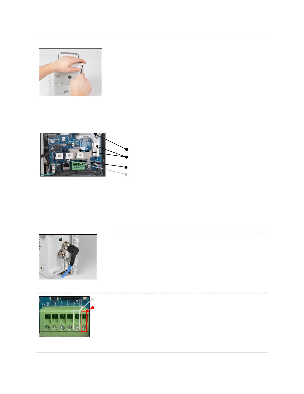
36
6
Access case interior
When working inside the unit, avoid contact with the battery, other
exposed components, and any item protected by the unit's interior plastic
cover. Avoid dropping or spilling anything into the case.
• Using a torx screwdriver with a T25 bit, unscrew and remove the four
fasteners that secure the case lid to the case base. Set aside the
fasteners for later reinstallation.
• The unit is hinged on the left; open the case lid from right to left.
• Bring in the customer-supplied Ethernet cable, power lines, or both
through the customer-installed conduit-hub. If both an Ethernet cable
and fixed DC power will be used, it is recommended that one conduit
be used for the Ethernet cable and the other for the power lines,
following AHJ requirements.
• Use the diagram below, left, to locate the optional connection ports
to be used: the terminal block, Ethernet cable port, and guides.
Protective cover
Guides (4x)
Terminal block
RJ45 port
7
Connect power
Choose only one option below (a or b) to select an external power input
for the RGX and follow that set of instructions.
WARNING: The RGX offers these power-input options: 12 V Charger
Port, IS Power Port, and 9–30 VDC Terminal Block. When connecting
external power, select only a single power-input type; connecting multiple
power inputs is not supported.
a
Power supply accessory (ISERTPS or ERTPS)
IMPORTANT: The warning above also applies to this option.
If the RGX will draw operational power from a compatible power supply
accessory (ISERTPS or ERTPS), connect the power supply's IS cable to
the unit’s IS Cable Adapter.
Ensure that the ISERTPS or ERTPS is installed, connected, and used in
accordance with the instructions provided in its product manual.
Skip to step 8.
Terminal block (detail)
GND
b
Fixed DC power
IMPORTANT: The warning above also applies to this option.
To complete the fixed DC power connections, count the terminal-block
ports from left to right, locating the fifth and sixth ports.
• Connect the ground line to Port 5, labeled "GND".
• Connect the compatible fixed DC power line to Port 6, labeled "PWR
IN 9V-30V ". This line supplies input voltage in the specified range
with a maximum current of 5.0A.
PWR IN
9V-30V
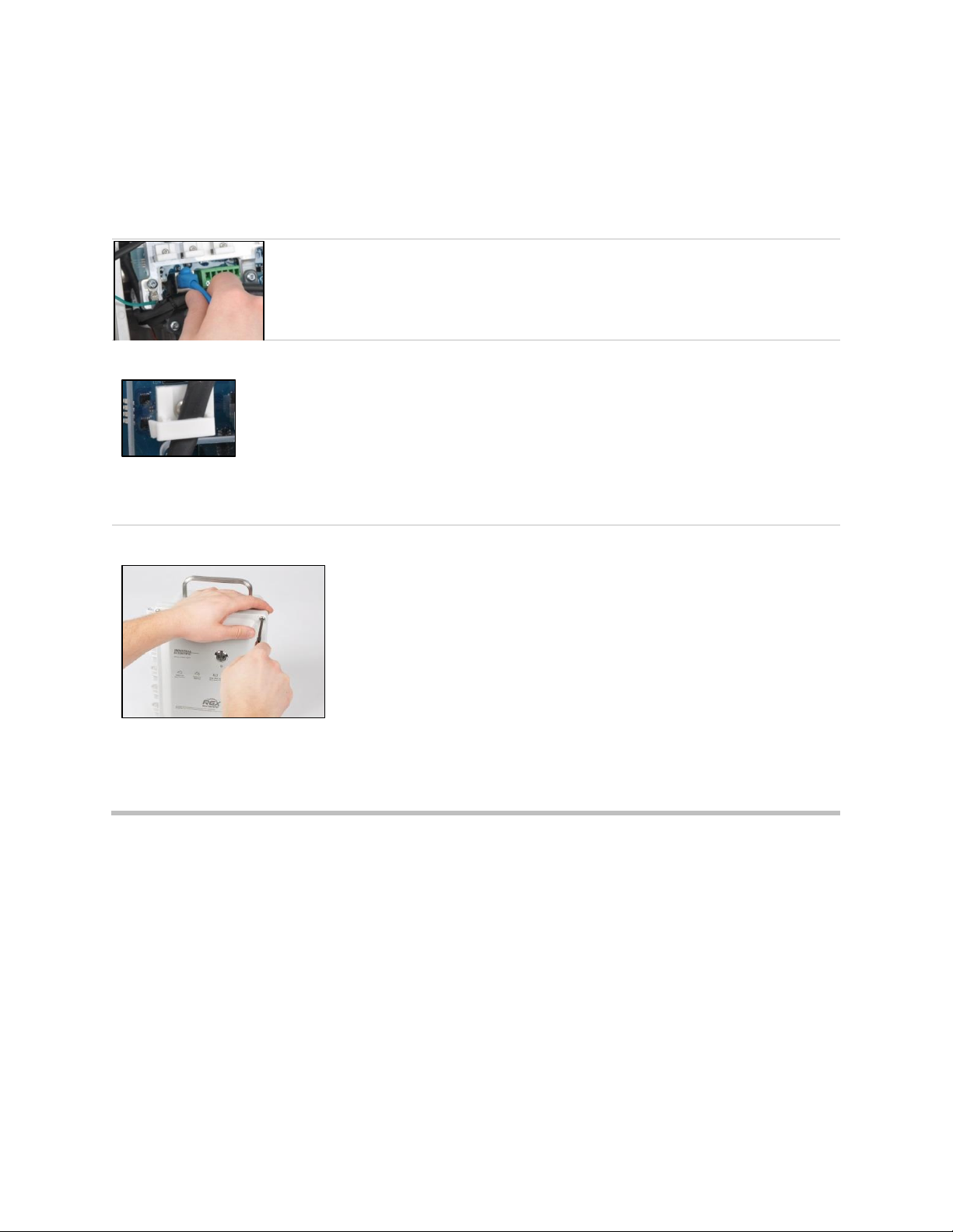
37
• Use these mechanical and electrical wiring specifications.
Mechanical:
o Solid Wire: 18-12 AWG
o Stranded Wire: 18-12 AWG
o Torque: 4.0 lb in (0.45 N m)
Electrical: Shield wiring, or conduit, at the source
8
Connect optional Ethernet cable
If an Ethernet connection will be used, connect the cable to its port.
9
Secure the cable and power line
Use the guides to secure the already connected Ethernet cable and
power line.
• Lift any guide by its tab.
• Place the cable or power line in the guide's groove.
• Lower and secure the tab to the guide base.
10
Close case lid and secure to case base
Ensure all wires and cables are:
• secure
• contained entirely inside the case
• away from the unit's closure surfaces
This supports the integrity of the items and full closure of the lid. If the
strain relief on the Ethernet cable resists full closure of the unit, use a 90°
adapter or short adapter cable. Close the case lid from left to right.
Using a T25 torx screwdriver, reinstall the four fasteners that secure the
case lid to the case base. Tighten them to a torque value of 1.69 N m
(240 oz in).
Figure 4.3 Installation that includes an external power source, Ethernet, or both
Operation Precheck
Power on the unit: On the case lid, press the power button for approximately 5 seconds until the powerbutton light turns on.
Observe the color and pattern of the power-button light, which indicates the unit's operational status. If the
light is solid green (not blinking)* the unit is fully operational. For information about other indicator-light
patterns, refer to Table 3.6 Power-button light indicators for more information.
*Note: When an RGX Gateway operating in LENS repeater mode is fully operational its power-button light displays a very slowly
blinking green light.


Chapter 5
Service and Warranty
Service
Service tasks for the RGX™ Gateway should be performed only by qualified personnel under the following
conditions.
• Perform service tasks only in a nonhazardous area.
• If an external power source is connected, de-energize the power source before servicing the unit.
• Ensure the unit is powered off; observe the power-button indicator light is off.
• Use only approved Industrial Scientific parts and accessories.
• Work on a nonconductive surface in a well-lit area.
• Wear grounding straps to prevent electrostatic discharge (ESD), which can damage the unit.
• To support ingress protection, refer to Table 5.1 and tighten the items to their stated torque values.
• When working with the magnet mounts, the following apply.
o Do not drill or abrade magnets; their powdered form is highly flammable.
o Use protective gloves and eyewear to avoid a potentially severe pinch injury, cut, or splinter.
Service tasks that can be completed by Industrial Scientific customers are described in this manual. Table
5.1 indicates which parts and components are customer replaceable. All other service tasks should be
performed only by Industrial Scientific or its authorized service centers.
Supplies
Torx screwdriver set
• T10 bit for port cap replacement
• T20 bit for conduit-hub plug removal or installation
• T25 bit for case fasteners
• T30 bit for wall mounts
Open-end wrenches
• 1/4 ″ for port cap replacement
• 3/8 ″ for conduit-hub plug removal or installation
• 3/4 ″ for vent replacement
• 18 mm for vent replacement
Additional supplies
• Isopropyl alcohol for fixed gasket replacement.
Instructions
Figure 5.1 provides partially disassembled views of the RGX Gateway, identifying customer replaceable
parts and components. This is followed by Table 5.1, which provides information about each part.

40
Figure 5.1 Replaceable parts diagram for the RGX Gateway
Table 5.1 RGX Gateway customer replaceable parts list
Diagram
number
Part name
Part
number
Notes
RGX
1
Case fastener
18109573
Four fasteners per pack
Fastener torque: 1.69 Nm (240 oz in)
2
Charging port cap
18109570
Includes tether-chain, screw, sealing gasket, washers and hex
nut.
3
IS power port cap
18109571
Includes tether-chain, screw, sealing gasket, washers and hex
nut.
4
Tether-chain screw
─
Screw torque: 0.63 Nm (90 oz in)
5
Vent
18109572
Vent nut torque: 1.27 Nm (180 oz in)
6
Conduit-hub plug
18109574
Screw torque: 1.27 Nm (180 oz in)
Accessories
—
Wall Mount Kit
17157620
Screw torque: 1.13 to 1.69 Nm (160 to 240 oz in)
—
Magnet Mount Kit
18109564
Do not use with a unit that will draw power from a DC fixed
power source.
Each magnet has a pull force of 67.6 kgf (149 lbf).
—
IS power cable adapter
18109575
Length: 62.2 cm (24.5 ″)

41
Figure 5.2 Instructions for service items installed on the case exterior: mounting kits and IS cable adapter.
Wall Mount Kit installation
—
Using the orientation shown, mate the hexagon cutout of the wall
mount to a corresponding corner on the back of the RGX.
The cross portion will extend past the edge of the case.
Using a T30 torx screwdriver,
turn the torx screw clockwise
to tighten.
Screw torque: 1.13 to 1.69
Nm (160 to 240 oz in)
Install the remaining wall
mounts.
—
In the kit, locate the supplied
label, which replicates
important information printed on
the back of the RGX.
Locate the unit’s LAN MAC
and WAN MAC values, printed
on the factory affixed label on
the back of the unit. Record
these two values onto the kit
label in the areas provided.
Affix the kit label to an area of
the RGX that will be visible
during operation.
Magnet Mount Kit installation
Do not use with a unit that will draw power from a DC fixed power source.
Insert magnet post into a threaded screw hole on the back of the
case; turn clockwise to tighten.
Repeat for second magnet installation.
The two magnets may be installed in the following
configurations: top, bottom, left side, right side, and diagonal.
Two magnet mounts will support the weight of the RGX; up to
four magnets may be installed.
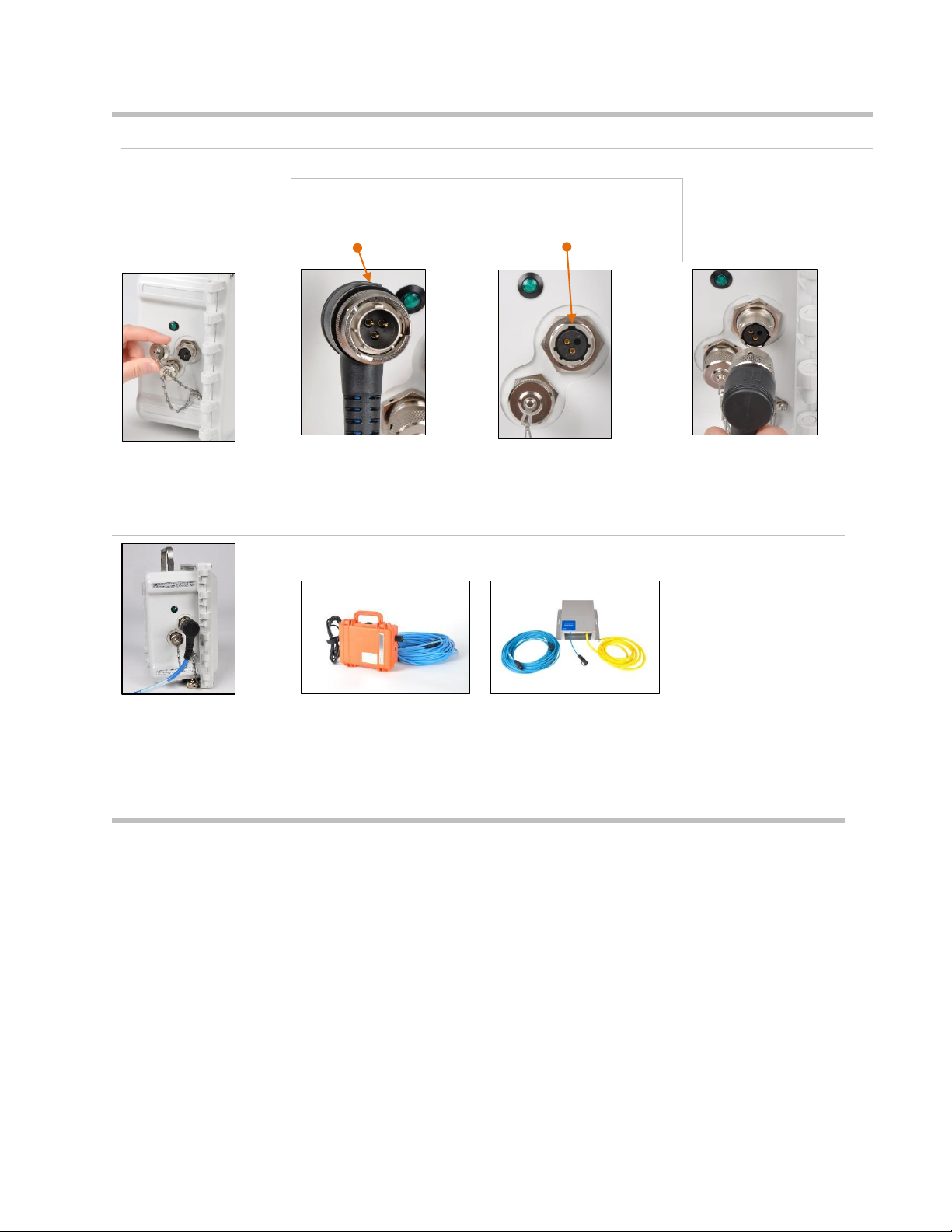
42
Intrinsic Safety (IS) Cable Adapter installation
IS Cable Adapter
connector
RGX IS port
Arrow
Wide notch
Turn the IS power port cap
counterclockwise
(approximately 45°) to
expose the port for use.
Align the arrow on the top of the adapter connector to the wide notch on the IS port; push on to
the port to connect.
Turn the swivel connector clockwise (approximately 45°) until it clicks closed or a full-stop
connection impact is felt.
—
—
Connect the other end of the adapter in accordance with the
Product Manual instructions from the compatible Industrial
Scientific power-supply accessory that will be used.
Figure 5.2 Mounting kit and IS cable adapter service tasks

43
Figure 5.3 Instructions for service items that require interior case access: conduit-hub plugs, vent, and
port caps.
Opening the case
Closing the case
Use a T25 torx screwdriver to
unscrew and remove the four
fasteners that secure the
case lid to the case base; set
aside the screws for later
reinstallation.
The unit is hinged on the left;
open the lid from right to left.
When closing the lid, ensure all wires and cables are secure
and are contained inside the case, away from its closure
surfaces.
Reinstall the four fasteners with the T25 torx bit to secure the
case lid to the case base. Screw torque: 1.69 Nm (240 oz in)
Conduit-hub plug removal and installation
Conduit-hub plug removal
Do not reinstall any used
conduit-hub plug
components; once removed,
a plug's seal is compromised
and other plug components
may become altered or
damaged.
Locate the conduit-hub plugs
at the bottom of the case
base.
Inside the case, hold the nut in place with a 3/8 ″ open-end
wrench and turn the T20 torx screw counterclockwise to
loosen.
Remove the nut, two internal
washers, the sealing gasket,
and one external washer from
the case.
To remove a worn or
damaged fixed gasket, push
the outer edge of the gasket
toward its center with a
finger; use friction and a
forward motion to separate
the gasket from the base.
Use the glue side of the removed gasket in a dabbing motion
to lift off remaining adhesive.
Rub all gasket-glue residue with a finger from the case base
and clean the area with isopropyl alcohol.

44
Conduit-hub Plug Kit installation
Use only an unused Conduit-
hub Plug Kit from Industrial
Scientific.
Do not reinstall any used
conduit-hub plug components;
once removed, a plug's seal is
compromised and other plug
components may become
altered or damaged.
Inside case
Hex nut with nylon insert
Flat washer
Sealing gasket
Washer
Fixed gasket
Outside case
Washer
T20 Torx screw
Remove the protective paper
to expose the adhesive side
of the gasket.
Inside the case, center and
place the gasket over the
conduit-hub plug opening on
the base.
From outside of the case,
place the torx screw into the
concave side of the washer,
and place over the base
opening.
Inside the case, place the
next washer—convex side
down—over the screw and
fixed gasket.
Follow with the sealing
gasket, flat washer, and hex
nut.
— — —
Hold the hex nut in place with a 3/8 ″ open-end wrench and
turn the T20 torx screw clockwise to tighten.
Screw torque: 1.27 Nm (180 oz in)

45
Vent replacement
To remove the vent, use an 18 mm open-end wrench to hold
the vent in place.
Inside the case, turn the nut counterclockwise with a 3/4 ″
open-end wrench to loosen and remove.
Discard the items according to company policy.
Insert the replacement vent into the hole from outside of the
case.
Inside the case, screw the nut onto the vent threads clockwise.
Hold the vent in place with the 18 mm open-end wrench; use
the 3/4 ″ open-end wrench to turn the nut clockwise to tighten.
Vent nut torque: 1.27 Nm (180 oz in)
Port cap removal and installation (IS port cap shown)
Port cap removal
To remove a worn or
damaged port cap, locate the
hex nut for the tethered-chain
screw inside the case.
Hold the hex nut in place with
a 1/4 ″ open-end wrench and
turn the T10 torx screw
counterclockwise to loosen.
Inside the case, remove the
nut, and one flat washer.
Lift the copper ground shield
to remove the second flat
washer and sealing gasket**.
Turn the port cap
counterclockwise
approximately 45°; separate
from the port.
Discard the removed items
according to company policy.
Port cap installation
Hex nut
Flat washer
Copper ground shield
Flat washer
Sealing gasket**
Connect the replacement port cap* to the appropriate port (IS
port or Charging port): turn clockwise (approximately 45°) until
it clicks closed or a full-stop connection impact is felt.
Insert the T10 torx screw through both tether-chain end rings,
and into the case screw hole.
* Always cap the port when it is not in use.
Inside the case, lift the copper ground shield enough to place
the sealing gasket** and flat washer over the tether-chain
screw; follow with the copper ground shield, second flat
washer, and hex nut.
Hold the hex nut in place with a 1/4 ″ open-end wrench and
turn the T10 torx screw clockwise to tighten.
Screw torque: 0.63 Nm (90 oz in)
**Replace the sealing gasket with every tether-chain screw
disassembly.
Figure 5.3 Conduit-hub plug, vent, and port cap service tasks

46
Warranty
Industrial Scientific Corporation’s RGX™ Gateways are warranted to be free from defects in material and
workmanship under normal and proper use and service for twenty-four (24) months from date of shipment.
This warranty includes batteries, except where otherwise stated in writing in the literature accompanying
the product. Industrial Scientific warrants that it will provide a cellular data plan for the life of the Gateway,
for a minimum of two years from time of purchase provided the customer maintains an active iNet® Now
account during that time; however, Industrial Scientific reserves the right to terminate any cellular data plan,
at its sole discretion, in the case of misuse by Buyer, including but not limited to using data for purposes
other than those described in this user manual and using data in regions outside of those originally
purchased.
Limitation of Liability
THE WARRANTY SET FORTH ABOVE IS STRICTLY LIMITED TO ITS TERMS AND IS IN LIEU OF ALL
OTHER WARRANTIES, GUARANTEES, EXPRESS OR IMPLIED, ARISING BY OPERATION OF LAW,
COURSE OF DEALING, USAGE OF TRADE OR OTHERWISE. INDUSTRIAL SCIENTIFIC MAKES NO
OTHER WARRANTIES, EITHER EXPRESSED OR IMPLIED, INCLUDING BUT NOT LIMITED TO THE
WARRANTIES OF MERCHANTABILITY OR FITNESS FOR PARTICULAR PURPOSE.
SHOULD THE PRODUCT FAIL TO CONFORM TO THE ABOVE WARRANTY, BUYER’S ONLY REMEDY
AND INDUSTRIAL SCIENTIFIC’S ONLY OBLIGATION SHALL BE, AT INDUSTRIAL SCIENTIFIC’S SOLE
OPTION, REPLACEMENT OR REPAIR OF SUCH NON-CONFORMING GOODS OR REFUND OF THE
ORIGINAL PURCHASE PRICE OF THE NONCONFORMING GOODS.
IN NO EVENT WILL INDUSTRIAL SCIENTIFIC BE LIABLE FOR ANY OTHER SPECIAL, INCIDENTAL,
CONSEQUENTIAL, PUNITIVE OR OTHER SIMILAR DAMAGES, INCLUDING LOSS OF PROFIT OR LOSS
OF USE, ARISING OUT OF THE SALE, MANUFACTURE OR USE OF ANY PRODUCTS SOLD
HEREUNDER WHETHER SUCH CLAIM IS PLEADED IN CONTRACT OR IN TORT, INCLUDING STRICT
LIABILITY IN TORT AND WHETHER INDUSTRIAL SCIENTIFIC HAS BEEN ADVISED OF THE POTENTIAL
FOR SUCH DAMAGES. Industrial Scientific’s total liability hereunder from any cause whatsoever (except
liability from personal injury caused by Industrial Scientific’s negligence), whether arising under contract,
warranty, tort (including negligence), strict liability, products liability or any other theory of liability, will be
limited to the lesser of Buyer’s actual damages or the price paid to Industrial Scientific for the Products that
are the subject of Buyer’s claim. All claims against Industrial Scientific must be brought within one year after
the cause of action arises, and Buyer expressly waives any longer statute of limitations.
It shall be an express condition to Industrial Scientific’s warranty that all products be carefully inspected for
damage by Buyer upon receipt, be properly calibrated for Buyer’s particular use, and be used, repaired, and
maintained in strict accordance with the instructions set forth in Industrial Scientific’s product literature. Repair
or maintenance by non-qualified personnel will invalidate the warranty, as will the use of non-approved
consumables or spare parts. As with any other sophisticated product, it is essential and a condition of
Industrial Scientific’s warranty that all personnel using the products be fully acquainted with their use,
capabilities and limitations as set forth in the applicable product literature.
Buyer acknowledges that it alone has determined the intended purpose and suitability of the goods
purchased. It is expressly agreed by the parties that any technical or other advice given by Industrial Scientific
with respect to the use of the goods or services is given without charge and at Buyer’s risk; therefore,
Industrial Scientific assumes no obligations or liability for the advice given or results obtained.

47
Appendix A
Requirements for electrical connections (Industrial
Scientific Control Drawing 1810D9509-200)
Figure A.1.A External electrical connections in a hazardous location
From
Figure
A.1.B

48
Figure A.1. B External electrical connections in a nonhazardous location
To
Figure
A.1.A

49
Figure A.1.C Internal electrical connections


Appendix B
Applicable Certification Standards
• UL 121201; Nonincendive Electrical Equipment for Use in Class I and II, Division 2 and Class III, Divisions 1
and 2 Hazardous (Classified) Locations; 9th Ed.
• UL 61010-1; Electrical Equipment for Measurement, Control, and Laboratory Use; Part 1: General
Requirements - 2nd Ed.; 2013/07/12
• UL 61010-2-201; UL Standard for Safety Requirements for Electrical Equipment for Measurement, Control,
and Laboratory Use - Part 2-201: Particular Requirements for Control Equipment – Ed. 1; 2017/02/20
• CSA C22.2 No. 213-17; Nonincendive Electrical Equipment for Use in Class I and II, Division 2 and Class
III, Divisions 1 and 2 Hazardous (Classified) Locations
• CSA 22.2 No. 61010-1-12; Electrical Equipment for Measurement, Control, and Laboratory Use; Part 1:
General Requirements – 3rd Ed.
• CSA 22.2 No. 61010-2-201:14; Electrical Equipment for Measurement, Control, and Laboratory Use; Part 2-
201: Particular Requirements for Control Equipment: 1st Ed.
• UL 2054; Standard for Household and Commercial Batteries; 2011/09/14
• IEC 60079-0:2017; Explosive atmospheres Part 0 - Equipment - General requirements
• IEC 60079-7:2017; Explosive atmospheres Part 7 - Equipment protection by increased safety ‘e’
• IEC 60079-11:2011; Explosive atmospheres Part 11 - Equipment protection by intrinsic safety ‘i’
• EN 60079-0:2018; Explosive atmospheres Part 0 - Equipment - General requirements
• EN 60079-7:2015 + A1:2018; Explosive atmospheres Part 7 - Equipment protection by increased safety ‘e’
• EN 60079-11:2012; Explosive atmospheres Part 11 - Equipment protection by intrinsic safety ‘i’
• UL 60079-0 - Explosive Atmospheres – Part 0: Equipment – General Requirements
• UL 60079-7 - Explosive Atmospheres- Part 7: Equipment Protection by Increased Safety "e"
• UL 60079-11 - Explosive Atmospheres - Part 11: Equipment Protection by Intrinsic Safety "i"
• CSA C22.2 No. 60079-0:19 Explosive atmospheres - Part 0: Equipment - General requirements
• CSA C22.2 No. 60079-7:16 Explosive atmospheres - Part 7: Equipment protection by increased safety "e"
• CSA C22.2 No. 60079-11:14 Explosive atmospheres - Part 11: Equipment protection by intrinsic safety "i"

Contact Information
Industrial Scientific Corporation
1 Life Way
Pittsburgh, PA 15205-7500 USA
Web: www.indsci.com
Phone: +1 412-788-4353 or 1-800-DETECTS (338-3287)
E-mail: info@indsci.com
Fax: +1 412-788-8353
Industrial Scientific France S.A.S.
5 Rue Frédéric Degeorge, CS 80097
62002 Arras Cedex, France
Web: www.indsci.com
Téléphone : +33 (0)1 57 32 92 61
E-mail: info@eu.indsci.com
Fax: +33 (0)1 57 32 92 67
英思科传感仪器(上海)有限公司
地址:中国上海市浦东金桥出口加工区桂桥路290号
邮编:201206
电话:+86 21 5899 3279
传真:+86 21 5899 3280
E-mail: info@ap.indsci.com
网址: www.indsci.com
服务热线:+86 400 820 2515
To locate a nearby distributor of our products or an Industrial
Scientific service center or business office, visit us at
www.indsci.com.
Rendez-vous sur notre site Web www.indsci.com, si vous
voulez trouver un distributeur de nos produits près de chez
vous, ou, si vous recherchez un centre de service ou un bureau
Industrial Scientific.
Besuchen Sie uns unter www.indsci.com, um einen
Vertriebshändler unserer Produkte oder ein Servicecenter bzw.
eine Niederlassung von Industrial Scientific zu finden.
Para buscar un distribuidor local de nuestros productos o un
centro de servicio u oficina comercial de Industrial Scientific,
visite www.indsci.com.
如需查找就近的产品经销商或 Industrial Scientific 服务中
心或业务办事处,请访问我们的网站 www.indsci.com
 Loading...