

Industrial Scientific RGX Product Manual
Product
Manual
The Safety Team's Resource
for
Operation
Part number: 17158071-1
T
y
T
Setup, Installation,
, and Service
Edition: 1
May 30, 2018
Document Number: 0000037533
DO NOT CHANGE WITHOUT THE FOLLOWING AGENCY APPROVALS(S):N/A
Printed By: Kuzmich, Bob
Date:May 29, 2018
Int: 1.5
Modified: 2018-05-25 13:18:14 ED
Created: 2018-05-16 10:24:51 ED
State:In Work
Rev: 1
INDUSTRIAL SCIENTIFIC CORPORATION
Title: PRODUCT MANUAL RGX GATEWAY-EN-1
Eng: Drawing No: 17158071-1Drawn By: Gaygan, Nanc

Industrial Scientific Corporation, Pittsburgh, PA USA
T
y
T
Industrial Scientific Co., Ltd. Shanghai, China
©2018 Industrial Scientific Corporation
All rights reserved. Published 2018.
Revision 1
www.indsci.com/rgxgateway
Document Number: 0000037533
DO NOT CHANGE WITHOUT THE FOLLOWING AGENCY APPROVALS(S):N/A
Printed By: Kuzmich, Bob
Date:May 29, 2018
Modified: 2018-05-25 13:18:14 ED
Int: 1.5
Created: 2018-05-16 10:24:51 ED
State:In Work
Rev: 1
INDUSTRIAL SCIENTIFIC CORPORATION
Title: PRODUCT MANUAL RGX GATEWAY-EN-1
Eng: Drawing No: 17158071-1Drawn By: Gaygan, Nanc

Contents
T
y
T
Warnings and Cautionary Statements ........................................................................................................... 1
Certification Summary ............................................................................................................................... 2
Chapter 1 ....................................................................................................................................................... 5
Product Information ....................................................................................................................................... 5
System Overview ...................................................................................................................................... 5
Key Features ............................................................................................................................................. 6
Location ................................................................................................................................................ 6
Communication and data security ......................................................................................................... 6
Mobility and mounting ........................................................................................................................... 6
Power .................................................................................................................................................... 7
Interior case access .............................................................................................................................. 7
Compatibilities ........................................................................................................................................... 7
Instruments ........................................................................................................................................... 7
Operational power sources ................................................................................................................... 7
Specifications ............................................................................................................................................ 8
RGX Gateway specifications ................................................................................................................. 8
Battery specifications .......................................................................................................................... 10
Power-supply accessory run-time effects............................................................................................ 10
Hardware Overview ................................................................................................................................. 10
Chapter 2 ..................................................................................................................................................... 13
Deployment Planning................................................................................................................................... 13
Introduction ............................................................................................................................................. 13
Communications...................................................................................................................................... 13
RGX Gateway−instrument communication (LENS Wireless) .............................................................. 13
RGX Gateway–iNet® communication ................................................................................................. 13
Settings and Connections ....................................................................................................................... 14
Sample Deployment Plans ...................................................................................................................... 15
Chapter 3 ..................................................................................................................................................... 21
Setup ........................................................................................................................................................... 21
Introduction ............................................................................................................................................. 21
Unpack .................................................................................................................................................... 21
Activation ................................................................................................................................................. 22
Document Number: 0000037533
DO NOT CHANGE WITHOUT THE FOLLOWING AGENCY APPROVALS(S):N/A
Printed By: Kuzmich, Bob
Date:May 29, 2018
Int: 1.5
Modified: 2018-05-25 13:18:14 ED
Created: 2018-05-16 10:24:51 ED
State:In Work
Rev: 1
i
INDUSTRIAL SCIENTIFIC CORPORATION
Title: PRODUCT MANUAL RGX GATEWAY-EN-1
Eng: Drawing No: 17158071-1Drawn By: Gaygan, Nanc

RGX Gateway ..................................................................................................................................... 22
T
y
T
Gas-detection instruments .................................................................................................................. 22
Charge .................................................................................................................................................... 23
Power On and Shutdown ........................................................................................................................ 24
Power on ............................................................................................................................................. 24
Shutdown ............................................................................................................................................ 24
Configuration ........................................................................................................................................... 24
Accessing and using the RGX Configuration Interface app ................................................................ 25
Installation Precheck ............................................................................................................................... 32
Chapter 4 ..................................................................................................................................................... 35
Installation and Operation ............................................................................................................................ 35
Introduction ............................................................................................................................................. 35
Site Selection .......................................................................................................................................... 37
Placement and Mounting ......................................................................................................................... 38
Installation Preparation ............................................................................................................................ 38
Installation ............................................................................................................................................... 39
Operation Precheck ................................................................................................................................. 43
Chapter 5 .................................................................................................................................................... 45
Service and Warranty .................................................................................................................................. 45
Service .................................................................................................................................................... 45
Supplies .............................................................................................................................................. 45
Instruction ........................................................................................................................................... 46
Warranty .................................................................................................................................................. 52
Limitation of Liability ............................................................................................................................ 52
Appendix A .................................................................................................................................................. 53
Supplemental information about external power connections ................................................................. 53
Contact Information ................................................................................................................................. 56
Document Number: 0000037533
DO NOT CHANGE WITHOUT THE FOLLOWING AGENCY APPROVALS(S):N/A
Printed By: Kuzmich, Bob
Date:May 29, 2018
Int: 1.5
Modified: 2018-05-25 13:18:14 ED
Created: 2018-05-16 10:24:51 ED
State:In Work
Rev: 1
ii
INDUSTRIAL SCIENTIFIC CORPORATION
Title: PRODUCT MANUAL RGX GATEWAY-EN-1
Eng: Drawing No: 17158071-1Drawn By: Gaygan, Nanc

Tables and Figures
T
y
T
Table 0.1 RGX Gateway hazardous location certifications ............................................................................ 2
Table 0.2 RGX Gateway wireless certifications ............................................................................................. 3
Figure 1.1 System overview .......................................................................................................................... 5
Table 1.1 RGX Gateway compatible gas-detection equipment...................................................................... 7
Table 1.2 RGX compatible extended run time power-supply accessories ..................................................... 8
Table 1.3 RGX Gateway intrinsic safety (IS) input parameters ...................................................................... 8
Table 1.4 RGX Gateway specifications ........................................................................................................ 9
Table 1.5 RGX Gateway factory-installed battery specifications.................................................................. 10
Table 1.6 Power supply run-time effects ...................................................................................................... 10
Figure 1.2.A Hardware overview (exterior) .................................................................................................. 11
Figure 1.2.B Hardware overview (interior) ................................................................................................... 12
Table 2.1 Required equipment settings for iNet Now live monitoring ........................................................... 14
Table 2.2 Range guidelines to maintain LENS Wireless connections .......................................................... 15
Figure 2.1.A LENS Wireless Group A instruments monitored: all ................................................................ 16
Figure 2.1.B LENS Wireless Group A instruments monitored: all but one ................................................... 17
Figure 2.1.C LENS Wireless Group B instruments monitored: all ................................................................ 18
Figure 2.1.D LENS Wireless Group B instruments monitored: all but one ................................................... 19
Table 3.1 Package contents ........................................................................................................................ 21
Figure 3.1 Required setup values ................................................................................................................ 22
Figure 3.2 Charge the unit ........................................................................................................................... 24
Table 3.2 Configuration applications ............................................................................................................ 25
Table 3.3 Supplies needed for configuration ............................................................................................... 25
Table 3.4 RGX Configuration Interface instruction sets by access method ................................................. 26
Figure 3.3 Wi-Fi access method for RGX Configuration Interface ............................................................... 28
Figure 3.4 Ethernet access method for RGX Configuration Interface .......................................................... 31
Table 3.5 Internal indicator lights and their meanings .................................................................................. 31
Figure 3.5 iNet settings ................................................................................................................................ 32
Table 3.6 Power-button light indicators ....................................................................................................... 33
Table 4.1 Customer-supplied equipment and services ................................................................................ 35
Figure 4.1 Distance requirements: ground-to-RGX and RGX-to-power-supply (ISERTPS shown) ............. 38
Table 4.2 Possible installation preparation tasks ......................................................................................... 38
Table 4.3 RGX Configuration Interface instruction sets ............................................................................... 39
Figure 4.2 Installation for RGX that excludes fixed DC power and excludes Ethernet ................................. 40
Figure 4.3 Installation for RGX that includes an external power source, Ethernet, or both .......................... 43
Figure 5.1 Replaceable parts diagram for the RGX Gateway ...................................................................... 46
Table 5.1 RGX Gateway customer replaceable parts list ............................................................................ 46
Document Number: 0000037533
DO NOT CHANGE WITHOUT THE FOLLOWING AGENCY APPROVALS(S):N/A
Printed By: Kuzmich, Bob
Date:May 29, 2018
Int: 1.5
Modified: 2018-05-25 13:18:14 ED
Created: 2018-05-16 10:24:51 ED
State:In Work
Rev: 1
iii
INDUSTRIAL SCIENTIFIC CORPORATION
Title: PRODUCT MANUAL RGX GATEWAY-EN-1
Eng: Drawing No: 17158071-1Drawn By: Gaygan, Nanc

Figure 5.2 Mounting kit and IS cable adapter service tasks ......................................................................... 48
T
y
T
Figure 5.3 Conduit-hub plug, vent, and port cap service tasks .................................................................... 51
Figure A.1.A Control drawing 1810D9509-200 revision 1 ............................................................................ 53
Figure A.1.B Control drawing 1810D9509-200 revision 1 ............................................................................ 54
Document Number: 0000037533
DO NOT CHANGE WITHOUT THE FOLLOWING AGENCY APPROVALS(S):N/A
Printed By: Kuzmich, Bob
Date:May 29, 2018
Int: 1.5
Modified: 2018-05-25 13:18:14 ED
Created: 2018-05-16 10:24:51 ED
State:In Work
Rev: 1
iv
INDUSTRIAL SCIENTIFIC CORPORATION
Title: PRODUCT MANUAL RGX GATEWAY-EN-1
Eng: Drawing No: 17158071-1Drawn By: Gaygan, Nanc

Risk of Explosion. For safety reasons, this equipment must be operated and serviced by qualified personnel
only. Read and understand the product manual completely before operating or servicing.
de réparer l'équipement.
AVERTISSEMENT: Une seule entrée à connecter à la fois
IMPORTANT: Fully charge the RGX™ Gateway before its first use.
IMPORTANT: Only charge the RGX Gateway battery at an ambient temperature range of 5 − 45°C (41 − 113°F).
IMPORTANT: Turn off all external power to the RGX Gateway before servicing the unit.
WARNING: Explosion Hazard. Do not open, maintain, or service where an explosive atmosphere may be present.
explosive peut être présente.
one of the following power input ports is permitted to be connected at a given time: 12V Charger Port,
IS Power Port, or 9–30 VDC Terminal Block.
CAUTION: RGX Gateway for use in hazardous locations only as to intrinsic safety per control drawing 1810D9509-200.
concerne la sécurité intrinsèque par schéma de commande 1810D9509-200.
WARNING: Potential electrostatic charging hazard. Only clean using a damp cloth.
AVERTISSEMENT: Risque potentiel de charge électrostatique. Nettoyez uniquement avec un chiffon humide.
WARNING: Substitution of components may impair intrinsic safety and may cause an unsafe condition.
AVERTISSEMENT: La substitution de composants peut compomettre la securite intinseque.
WARNING: Connect or disconnect only in a non-hazardous area.
battery may present a risk of fire or explosion. The battery used in this device may present a risk of fire or chemical burn
if mistreated. Do not crush, disassemble, or incinerate.
IMPORTANT: Batteries are to be disposed or recycled accordingly to local laws and regulations.
detergent.
This device complies with Part 15 of the FCC Rules for Intentional Radiators. Operation is subject to the following two
Changes or modifications not expressly approved
by the manufacturer could void the user’s authority to operate the equipment.
T
y
T
Warnings and Cautionary Statements
CAUTION:
AVERTISSEMENT: Risques d’explosion. Pour des raisons de sécurité, cet équipment doit étre utilesé entretenu et
réparé uniquement par un personnel qualifié. Étudier le manuel d'instructions en entire avant d'utiliser, d'entretenir ou
WARNING: Only one input to be connected at a time
AVERTISSEMENT: Ne pas ouvrir sous tension. N'ouvrez pas, ne maintenez pas, ou service où une atmosphère
WARNING: Explosion Hazard. Do not connect or disconnect where an explosive atmosphere may be present.
AVERTISSEMENT: Risques d’explosion. Ne pasbrancher ni débrancher où une atmosphère explosive peut être
présente.
WARNING: Only
AVERTISSEMENT: RGX Gateway pour une utilisation dans des emplacements dangereux uniquement en ce qui
CAUTION: Battery pack is only Industrial Scientific technician replaceable with ISC P/N 17157552; use of another
IMPORTANT: Equipment warning and marking must be legible during normal use. Clean with soft cloth and mild
conditions: (1) This device may not cause harmful interference, and (2) this device must accept any interference
received, including interference that may cause undesired operation.
Document Number: 0000037533
DO NOT CHANGE WITHOUT THE FOLLOWING AGENCY APPROVALS(S):N/A
Printed By: Kuzmich, Bob
Date:May 29, 2018
Int: 1.5
Modified: 2018-05-25 13:18:14 ED
Created: 2018-05-16 10:24:51 ED
State:In Work
Rev: 1
1
INDUSTRIAL SCIENTIFIC CORPORATION
Title: PRODUCT MANUAL RGX GATEWAY-EN-1
Eng: Drawing No: 17158071-1Drawn By: Gaygan, Nanc

This equipment generates and radiates radio frequency energy during normal operation. It could cause interference
x Consult the dealer or an experienced radio/TV technician for help.
requirements.
This device complies with Industry Canada license-exempt RSS standard(s). Operation is subject to the following two
compromettre le fonctionnement.
separation distance
magnet or metal surface and cause injury. The magnet material is brittle; it can crack or splinter on impact to cause
Keep magnets away from electronic devices, identification cards, and credit cards that use microchips, magnets, or
magnetic fields.
Table 0.1 RGX Gateway hazardous location certifications
Certifying Body
Classificationa
Approved temperature range
Temperature Class T6
a
To determine the hazardous-classified areas for which a unit is certified, refer to its label.
T
y
T
with other types of radio communications if not installed in accordance with the installation instructions. There is no
guarantee that interference will not occur in a particular installation even if installed in accordance with these
instructions. If it is determined that this equipment is causing interference to radio communications (by turning this
equipment off and on), the interference may be corrected by one or more of the following measures:
x
Reorient or relocate the receiving antenna.
x
Increase the separation between the equipment and receiver.
Connect the equipment into an outlet on a circuit different from that to which the receiver is connected.
x
This device is only compliant for use in fixed and mobile operation applications. Install this device to maintain at least
20 cm (8 inches) separation distance between the RGX Gateway and anywhere personnel may be present for
prolonged periods of time to meet FCC, ISED and other international radio frequency (RF) exposure safety
conditions: (1) this device may not cause interference, and (2) this device must accept any interference, including
interference that may cause undesired operation of the device.
Le présent appareil est conforme aux CNR d'Industrie Canada applicables aux appareils radio exempts de licence.
L'exploitation est autorisée aux deux conditions suivantes : (1) l'appareil ne doit pas produire de brouillage, et (2)
l'utilisateur de l'appareil doit accepter tout brouillage radioélectrique subi, même si le brouillage est susceptible d'en
The RGX Gateway's optional Magnet Mount Kit and individual kit items can cause injury. To avoid injury, Industrial
Scientific recommends the following.
Persons with a pacemaker or implantable cardio defibrillator (ICD) should maintain a minimum
x
of 90 cm (36 ″) between the pacemaker or ICD and the magnet. Please consult your physician or pacemaker or
ICD manufacturer for additional guidance and recommendations.
Neodymium magnets have a strong attractive force. Each can attract quickly when in close proximity to another
x
injury and potentially become a flying hazard. Use protective gloves and eyewear to avoid a potentially severe
pinch injury, cut, or splinter.
Do not use magnet mounts with units that will draw power from a fixed DC power source.
x
x
Certification Summary
At the time of this document’s publication, the RGX Gateway was certified for use as summarized below.
To determine the hazardous-area classifications for which a unit is certified, refer to its label or the
equipment order.
c UL us Class I, Division 2, Groups A, B, C, and D,
–20 °C to +55 °C (–4 °F to + 131 °F)
Document Number: 0000037533
DO NOT CHANGE WITHOUT THE FOLLOWING AGENCY APPROVALS(S):N/A
Printed By: Kuzmich, Bob
Date:May 29, 2018
Int: 1.5
Modified: 2018-05-25 13:18:14 ED
Created: 2018-05-16 10:24:51 ED
State:In Work
Rev: 1
2
INDUSTRIAL SCIENTIFIC CORPORATION
Title: PRODUCT MANUAL RGX GATEWAY-EN-1
Eng: Drawing No: 17158071-1Drawn By: Gaygan, Nanc

Table 0.2 RGX Gateway wireless certifications
Agency or
authority
Identification number
Country or region
FCC
CC3102MOD, and RI7LE910SV
USA
LE910SV
T
y
T
In addition to the certified wireless uses summarized below, refer to the Industrial Scientific website for the
most up-to-date information on wireless product certifications.
PHH-RGX, U90-SM220, SQGBL652, Z64-
ISED-Canada 20727-RGX, 7084A-SM220, 3147A-BL652, 451l-
CC3120MOD, 5131A-LE910NA, and 5131A-
Canada
Document Number: 0000037533
DO NOT CHANGE WITHOUT THE FOLLOWING AGENCY APPROVALS(S):N/A
Printed By: Kuzmich, Bob
Date:May 29, 2018
Int: 1.5
Modified: 2018-05-25 13:18:14 ED
Created: 2018-05-16 10:24:51 ED
State:In Work
Rev: 1
3
INDUSTRIAL SCIENTIFIC CORPORATION
Title: PRODUCT MANUAL RGX GATEWAY-EN-1
Eng: Drawing No: 17158071-1Drawn By: Gaygan, Nanc

T
y
T
Document Number: 0000037533
DO NOT CHANGE WITHOUT THE FOLLOWING AGENCY APPROVALS(S):N/A
Printed By: Kuzmich, Bob
Date:May 29, 2018
Modified: 2018-05-25 13:18:14 ED
Int: 1.5
Created: 2018-05-16 10:24:51 ED
State:In Work
Rev: 1
INDUSTRIAL SCIENTIFIC CORPORATION
Title: PRODUCT MANUAL RGX GATEWAY-EN-1
Eng: Drawing No: 17158071-1Drawn By: Gaygan, Nanc
Product Information
Hardware Overview
iNet
(live monitoring and
real-time alerts)
T
y
T
System Overview
Key Features
Compatibilities
Specifications
System Overview
Chapter 1 1
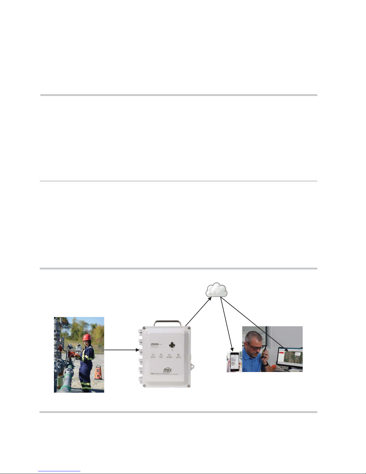
As shown below, the RGX™ Gateway (RGX) facilitates data exchange between compatible, enabled
Industrial Scientific gas-detection instruments and iNet®. The exchanged data are used to support the livemonitoring capabilities of iNet Now. From a computer or smart-device, iNet Now users can learn, on a live
basis, about everything from instrument gas readings to gas alarms, man-down events, panic alarms, and
more.
This wirelessly connected, live-monitoring system, as depicted below, enhances the safety team's quick
responses to and preparedness for hazardous events.
Instrument data RGX Gateway iNet Now users
Document Number: 0000037533
DO NOT CHANGE WITHOUT THE FOLLOWING AGENCY APPROVALS(S):N/A
Printed By: Kuzmich, Bob
Date:May 29, 2018
Int: 1.5
Modified: 2018-05-25 13:18:14 ED
Created: 2018-05-16 10:24:51 ED
Figure 1.1 System overview
State:In Work
Rev: 1
INDUSTRIAL SCIENTIFIC CORPORATION
Title: PRODUCT MANUAL RGX GATEWAY-EN-1
Eng: Drawing No: 17158071-1Drawn By: Gaygan, Nanc

T
y
T
Key Features
Location
The RGX Gateway is suitable for indoor or outdoor use in locations that meet the product's certified uses
and specifications. Indoor operation is suitable only when a unit's GPS location is not needed.
Communication and data security
Instrument–RGX Gateway
LENS™ Wireless (Linked Equipment Network for Safety) is a long-range, power-efficient wireless mesh
network from Industrial Scientific. LENS functionality enables data sharing among wirelessly connected
equipment items—gas-detection instruments and RGX Gateway units—that are set to operate within a
specified LENS group (e.g., Group A). The following also apply.
x Ten named LENS groups are available.
x Each group can host up to 25 equipment items.
x More than one RGX can be included in a LENS group.
Instrument data exchanged through LENS are automatically encrypted with the Industrial Scientific key.
Encryption can also be set to use a customer-supplied key. All equipment items in the group must be set to
the same key.
RGX Gateway–iNet
The RGX can send data it receives from gas-detection instruments to iNet through these transmission
options: wireless local area network (Wi-Fi), cellular, and Ethernet.
The customer sets each transmission option to on or off, allowing the RGX to maximize or to limit the
number of channels through which it can exchange data with iNet. When more than one option is on, the
customer prioritizes the order in which the unit will use them. For example, if Wi-Fi and cellular are on, the
unit can be set to first use Wi-Fi and if that is not available, use cellular.
The RGX–iNet data exchanges are automatically encrypted using the Industrial Scientific encryption key.
Optionally, a customer-supplied key may be used.
Mobility and mounting
The versatile RGX is designed for transportability and for permanent installation. It can be left unmounted
for more mobile applications or mounted for permanent operation.
The RGX features a durable, factory-installed handle, which allows for a unit’s ready relocation from site to
site when mobility is a factor. It can be transported in its optional case, which provides added protection for
the unit, visibility to the unit's operational status indicator, and access to the unit's handle.
Based on the application, the RGX can be surface mounted or mounted to a customer-supplied strut-type
rail installation using the optional Wall Mount Kit. The RGX can also be secured to a metal surface using
the optional Magnet Mount Kit; however, do not use magnet mounts with a unit that will draw power from a
fixed DC power source.
Document Number: 0000037533
DO NOT CHANGE WITHOUT THE FOLLOWING AGENCY APPROVALS(S):N/A
Printed By: Kuzmich, Bob
Date:May 29, 2018
Int: 1.5
Modified: 2018-05-25 13:18:14 ED
Created: 2018-05-16 10:24:51 ED
State:In Work
Rev: 1
6
INDUSTRIAL SCIENTIFIC CORPORATION
Title: PRODUCT MANUAL RGX GATEWAY-EN-1
Eng: Drawing No: 17158071-1Drawn By: Gaygan, Nanc

Table 1.1 RGX Gateway compatible gas-detection equipment
Instrument
firmware version
LENS Wireless
Industrial Scientific
P
roduct Manual
part
number
Ventis® Pro Series
V3.0 or higher
Yes
17156830
T
y
T
Power
The RGX Gateway offers a variety of operational power options.
x The RGX can be powered solely by its rechargeable, factory-installed lithium-ion battery. This option is
well suited for short-term use conditions that allow for the unit to be situated, between use cycles, in a
nonhazardous location for charging.
x The RGX can receive operational power from a compatible, customer-supplied and customer-installed
fixed DC power source. This option is suitable for permanent installations.
x The RGX can receive operational power from a compatible power-supply accessory only from
Industrial Scientific; use of each accessory requires the RGX be equipped with its Intrinsic Safety (IS)
Cable Adapter. This option is well suited for use conditions that do not require permanent installation,
but demand a run time exceeding that of the factory-installed battery.
x In a nonhazardous location only, the RGX can draw operational power from its charging power supply.
Interior case acces s
The unit's interior is accessed by removing four screws from the case lid. To help restrict access, the case
features tabs to accommodate a customer-supplied lock that is suitable for the location.
The unit features two conduit-hub openings, each sealed with a factory-installed plug. The conduit-hub
plugs should not be removed except for permanent installations that will make use of customer-supplied
conduit-hub fixtures as needed for the connection of a compatible fixed DC power source, Ethernet cable,
or both.
Compatibilities
Instruments
Use the information supplied below to ensure gas-detection instruments are compatible with the RGX
Gateway. As needed, upgrade instrument firmware to the required version, add LENS Wireless
functionality, and refer to the instrument's product manual.
Required
required
Radius® BZ1 Area Monitor V3.0 or higher Yes 17155915
Operational power sources
WARNING: Only one of the following power input ports is permitted to be connected at a given time: 12V
Charger Port, IS Power Port, or 9–30 VDC Terminal Block.
The RGX can draw operational power from its factory-installed rechargeable lithium-ion battery, which can
be charged in a nonhazardous location using the RGX charging power supply.
The operational run time for the factory-installed battery can be extended with the use of a compatible
power-supply accessory only from Industrial Scientific. Each power-supply accessory, as listed below, has
Document Number: 0000037533
DO NOT CHANGE WITHOUT THE FOLLOWING AGENCY APPROVALS(S):N/A
Printed By: Kuzmich, Bob
Date:May 29, 2018
Int: 1.5
Modified: 2018-05-25 13:18:14 ED
Created: 2018-05-16 10:24:51 ED
State:In Work
Rev: 1
7
INDUSTRIAL SCIENTIFIC CORPORATION
Title: PRODUCT MANUAL RGX GATEWAY-EN-1
Eng: Drawing No: 17158071-1Drawn By: Gaygan, Nanc

Table 1.2 RGX compatible extended run time power-supply accessories
Power supplye
part
number
part number
IS
Cable Adapter
18109575 (adapter)
supply
18109575 (adapter)
Table 1.3 RGX Gateway intrinsic safety (IS) input parameters
Item
Value
Ui
16.2 VDC
Ii
0.980 A
Pi
2.2 W
Ci
0 μF
Li
0 mH
T
y
T
unique use restrictions or certified uses. Before using either accessory, read and understand its product
manual and control drawing. The control drawing is provided in the power supply's product manual (part
numbers provided below), and in this "Product Manual”, Appendix A Supplemental information
about external power connections.
Orderable
Intrinsically Safe Extended Run Time Power Supplya
(ISERTPS), Intrinsic Safety (IS) Cable, and the RGX
Extended Run Time Power Supplya (ERTPS) Kit
(includes IS Cable) and the RGX IS Cable Adapter
a
When used with the RGX Gateway, ensure a distance of 5 m (16 ' 4 ″) between the RGX and its power-supply accessory from Industrial
Scientific, or any that are in use nearby.
b
Where X indicates regional power-cord type (1 for NA, 2 for EU, 3 for AU, and 4 for UK).
18109516 (power supply)
17156261 (cable)
18109388-XAb (power-
kit)
Product Manual
17158248
17158385
The RGX Gateway's input power parameters are provided below.
The RGX Gateway can be operated using customer-supplied, customer-installed fixed DC power that
supplies a compatible input voltage range of 9–30 VDC with a maximum current of 5A and is connected to
the dedicated ports on the RGX terminal block. Before connecting power, read and understand the control
drawing 1810D9509-200 in Appendix A Supplemental information about external power
connections of this "Product Manual".
The RGX charging power supply and power cord (part number 17158665) can be used to provide
operational power to the unit only when the unit is operated in a nonhazardous location.
Specifications
RGX Gateway specifications
Ensure all aspects of unit installation and operation are consistent with the product's specifications supplied
below.
Document Number: 0000037533
DO NOT CHANGE WITHOUT THE FOLLOWING AGENCY APPROVALS(S):N/A
Printed By: Kuzmich, Bob
Date:May 29, 2018
Int: 1.5
Modified: 2018-05-25 13:18:14 ED
Created: 2018-05-16 10:24:51 ED
State:In Work
Rev: 1
8
INDUSTRIAL SCIENTIFIC CORPORATION
Title: PRODUCT MANUAL RGX GATEWAY-EN-1
Eng: Drawing No: 17158071-1Drawn By: Gaygan, Nanc

Table 1.4 RGX Gateway specifications
Item
Description
IS power: 16.2 VDC, 0.980A
Size (length x width x depth)
28 cm x 23 cm x 15 cm (11 ″ x 9 ″ x 6 ″)
Weight
2.5 kg (5.6 lb)
Case materials
Polycarbonate
Ingress protection
IP65
Wet location rated
Yes
Environmental rating
Type 1 (outdoor use)
Pollution degree
2
Overvoltage category
≤60 volts
External buttons and indicators
Buttons
One; power button on case lid
Indicator light on side panel (indicates battery charging status)
Internal buttons and indicators
Buttons
One; SW1 RESET (resets the unit to its original factory-setting values)
ERR1 indicates system error.
Green indicates connection speed.
Operating conditions
Ambient temperature
–20 °C to +55 °C (–4 °F to +131 °F)
Humidity
5−95% relative humidity (RH) noncondensing (continuous)
Altitude
Use only at altitudes below 2000 m (6560 ')
Storage conditionsa
Temperature
–40 °C to +80 °C (–40 °F to +176 °F)
When a unit is stored for more than 30 consecutive days, fully charge the battery before powering on the unit.
T
y
T
Power input Three
x
x
x
Terminal block: 9-30 VDC, 5A (Hazardous Locations)
12V power supply: 12VDC, 5A (Nonhazardous Locations Only)
Indicators Two
x
Power-button light (colors and patterns indicate operational status)
x
Status indicators Four
x
COMM indicates communication status.
LENS indicates LENS Wireless status.
x
ERR2 indicates communication error.
x
x
Ethernet indicators Two
x
Yellow indicates connection status.
x
a
Document Number: 0000037533
DO NOT CHANGE WITHOUT THE FOLLOWING AGENCY APPROVALS(S):N/A
Printed By: Kuzmich, Bob
Date:May 29, 2018
Int: 1.5
Modified: 2018-05-25 13:18:14 ED
Created: 2018-05-16 10:24:51 ED
State:In Work
Rev: 1
9
INDUSTRIAL SCIENTIFIC CORPORATION
Title: PRODUCT MANUAL RGX GATEWAY-EN-1
Eng: Drawing No: 17158071-1Drawn By: Gaygan, Nanc

Table 1.5 RGX Gateway factory-installed bat t ery specifications
Item
Value
Battery type
Rechargeable lithium-ion
Run timea
168 hours
Battery charge timeb
up to 8 hours
Charging cycles
up to 1500 cycles minimum
Charging temperature rangec
5−45°C (41−113°F)
Nominal voltage
3.65 VDC
Nominal capacity
61 Wh
Table 1.6 Power supply run-time eff ects
Power supply (Product Manual part number)
RGX run time
Intrinsically Safe Extended Run Time Power Supply (17158248)
Indefinite
Extended Run Time Power Supply (17158385)
Indefinite
T
y
T
Battery specifications
Run time, operating temperature, and other specifications for the RGX factory-installed battery are provided
below.
a
Approximate run time when all of the following statements are true. The RGX battery is new and fully charged. The RGX is operating at room temperature (25
°C [77 °F]) using any or all communication options. The GPS setting is on and set to send location data every 60 minutes. The LENS group includes up to 25
equipment items. The RGX transmits up to 60 minutes of alarm data every 24 hours and is set to upload noncritical data every five minutes.
b
When charged at room temperature (25°C [73 °F]).
c
Battery charging is suspended in temperatures below 5 °C (41 °F) and above 45 °C (113 °F).
Power-supply accessory run-time effects
The RGX Gateway can draw operational power from compatible power-supply accessories only from
Industrial Scientific. Provided below are the run-time estimates for the RGX when it is used with each
accessory.
Each power-supply accessory has its own use restrictions. Refer to an accessory's Product Manual to
determine if the power supply suits the application and to ensure it is used in accordance with its manual.
Hardware Overview
The main hardware components of the RGX Gateway are identified below in Figure 1.2.A and Figure 1.2.B
(exterior and interior, respectively).
Document Number: 0000037533
DO NOT CHANGE WITHOUT THE FOLLOWING AGENCY APPROVALS(S):N/A
Printed By: Kuzmich, Bob
Date:May 29, 2018
Int: 1.5
Modified: 2018-05-25 13:18:14 ED
Created: 2018-05-16 10:24:51 ED
State:In Work
Rev: 1
10
INDUSTRIAL SCIENTIFIC CORPORATION
Title: PRODUCT MANUAL RGX GATEWAY-EN-1
Eng: Drawing No: 17158071-1Drawn By: Gaygan, Nanc

Case lid
Case base
Fastener (4x);
1.69 N m; 240 oz in screw torque
Hinge
Power button
powerstatus)
NFC target
Indicator light
(charging status)
power
port and tethered cap
port
and tethered cap
screw
customer-supplied item)
Top
Bottom
Handle
Figure 1.2.A Hardware overview (exterior)
T
y
T
Indicator light (system-
communication
Side (left) Side (right)
Handle
Screw hole (4x); for use with
optional Wall Mount kit or
Magnet Mount kit
Labels
MAC addresses
(on label)
Serial number (S/N)
Intrinsic safety (IS)
Charging power supply
Tether-chain
Vent
Lock tabs (for use with
Activation code
Conduit-hub plug (2x); each
covers a hole size of 27.8 mm
(1.094 ″)
Document Number: 0000037533
DO NOT CHANGE WITHOUT THE FOLLOWING AGENCY APPROVALS(S):N/A
Printed By: Kuzmich, Bob
Date:May 29, 2018
Int: 1.5
Modified: 2018-05-25 13:18:14 ED
Created: 2018-05-16 10:24:51 ED
State:In Work
Rev: 1
11
INDUSTRIAL SCIENTIFIC CORPORATION
Title: PRODUCT MANUAL RGX GATEWAY-EN-1
Eng: Drawing No: 17158071-1Drawn By: Gaygan, Nanc
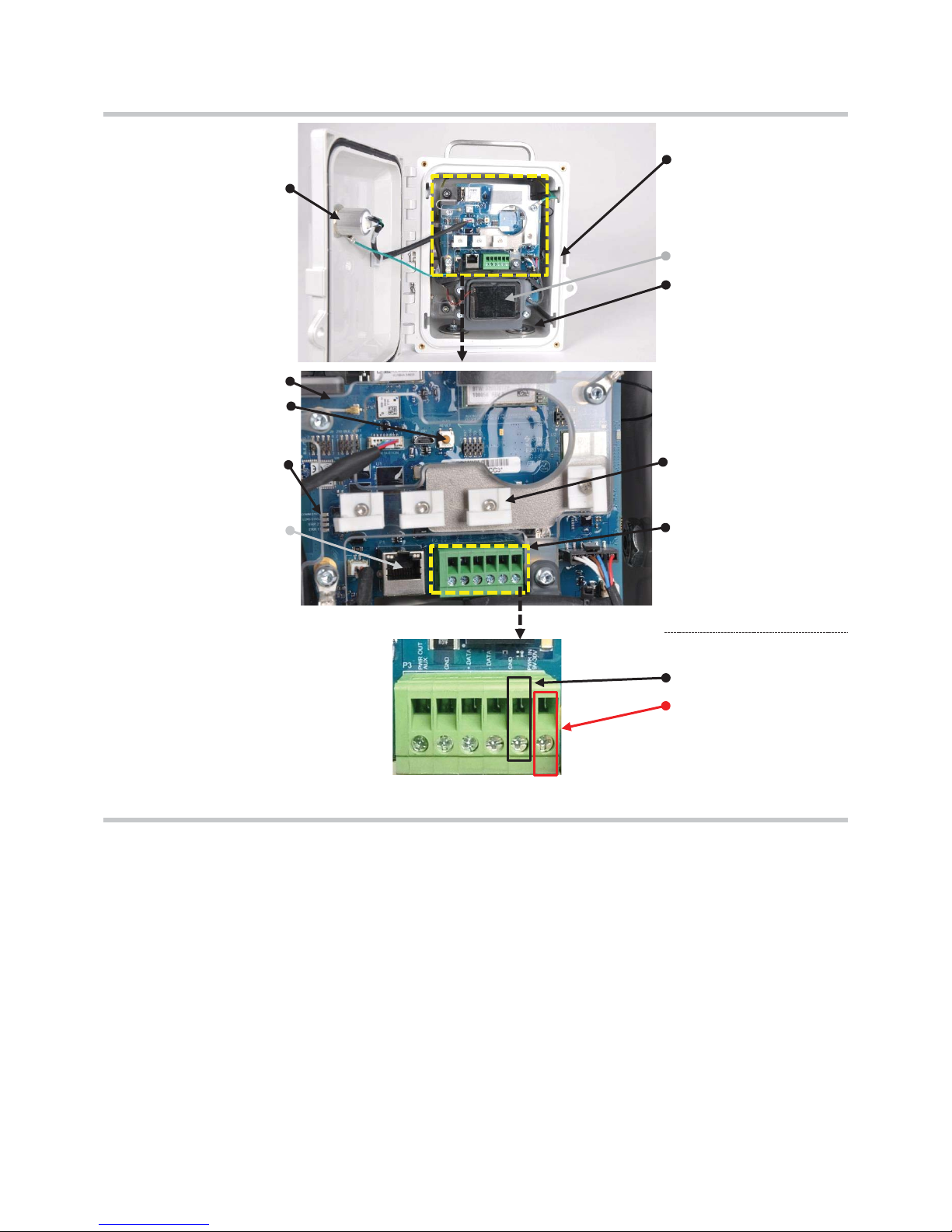
Vent nut (behind vent)
button assembly
Protective plastic cover
Factory reset buttonb
Indicator lights
(from top to bottom: COMM,
LENS, ERR2, and ERR1)
RJ45 port
supplied
)
30 VDC
a
For use with customer-supplied, customer-installed fixed DC power that supplies a compatible input voltage range of 9–30 VDC with a
maximum current of 5A and is connected to the dedicated ports on the RGX terminal block.
b
When the factory reset button is pressed and held for approximately 20 seconds, the unit’s settings will revert to the original factory-setting
values. After a reset, adjust unit settings as needed.
T
y
T
Power-
Battery
(for use with customer-
Ethernet cable
Conduit-hub plug
(2x)
Wire and cable guides (4x)
Terminal blocka
Terminal blocka
GND
PWR IN 9V–30V (9–
with 5A maximum current)
Figure 1.2.B Hardware overview (interior)
Document Number: 0000037533
DO NOT CHANGE WITHOUT THE FOLLOWING AGENCY APPROVALS(S):N/A
Printed By: Kuzmich, Bob
Date:May 29, 2018
Int: 1.5
12
Modified: 2018-05-25 13:18:14 ED
Created: 2018-05-16 10:24:51 ED
State:In Work
Rev: 1
INDUSTRIAL SCIENTIFIC CORPORATION
Title: PRODUCT MANUAL RGX GATEWAY-EN-1
Eng: Drawing No: 17158071-1Drawn By: Gaygan, Nanc

Deployment Planning
Sample Deployment Plans
T
y
T
Chapter 2 2
Introduction
Communications
Settings and Connections
Introduction
Whether you are using a single RGX™ Gateway or multiple units, this chapter will help you make decisions
about how each is to operate within your applications. Communications, settings, and wireless connections
are reviewed and illustrations are provided to depict simplified, sample deployment plans.
Communications
When using the RGX, two wireless networks are involved. One network allows the RGX to communicate
with gas-detection instruments. The other network allows the RGX to send instrument data to iNet®, which
supports the live-monitoring capabilities of iNet Now. Both networks are discussed below.
RGX Gateway−instrument communication (LENS Wireless)
The RGX can communicate with gas-detection instruments only when the equipment items are set to
operate in the same named LENS™ Wireless group, and other requirements (settings and connections)
are met. The following apply to or should be decided for deployment planning and setup preparation.
x Decide which named LENS group (e.g. "Group A") the RGX will monitor.
x A LENS group can include up to 25 equipment items, counting gas-detection instruments and RGX
units.
x More than one RGX unit can be set to monitor a single LENS Group (iNet manages for any duplication
of instrument data sent from multiple RGX units).
RGX Gateway–iNet® communication
The RGX Gateway is set, by the customer, to communicate with iNet using one or more options—Wi-Fi,
cellular, and Ethernet. Your choices may be subject to your company's communication preferences and
security guidelines. If you are not familiar with your company's communication operations, see your network
administrator. For deployment planning and setup preparation, determine the following.
x Decide which of the three communication options a unit will use.
Document Number: 0000037533
DO NOT CHANGE WITHOUT THE FOLLOWING AGENCY APPROVALS(S):N/A
Printed By: Kuzmich, Bob
Date:May 29, 2018
Modified: 2018-05-25 13:18:14 ED
Int: 1.5
Created: 2018-05-16 10:24:51 ED
State:In Work
Rev: 1
INDUSTRIAL SCIENTIFIC CORPORATION
Title: PRODUCT MANUAL RGX GATEWAY-EN-1
Eng: Drawing No: 17158071-1Drawn By: Gaygan, Nanc
 Loading...