

Industrial Scientific Radius BZ1 Product Manual

Product
Manual
The Essential Guide for
Safety Teams and
Instrument Operators
Edition: 7
May 30, 2018
Part Number: 17155915-1

Industrial Scientific Corporation, Pittsburgh, PA USA
Industrial Scientific Co., Ltd. Shanghai, China
© 2016, 2017, 2018 Industrial Scientific Corporation
All rights reserved. Published 2018.
Version 9
www.indsci.com/radius

i
Contents
General Information ....................................................................................................................................... 1
Certifications .............................................................................................................................................. 1
Warnings and Cautionary Statements ....................................................................................................... 2
Recommended Practices ........................................................................................................................... 4
First-use Checklist ................................................................................................................................. 4
Placement Guidelines ............................................................................................................................ 4
Gas and site factors ........................................................................................................................... 4
Wireless and GPS factors .................................................................................................................. 4
Maintenance .......................................................................................................................................... 5
Settings .............................................................................................................................................. 6
Utilities ............................................................................................................................................... 6
Biased Sensors ..................................................................................................................................... 7
Remote Sampling .................................................................................................................................. 8
Care and Storage .................................................................................................................................. 9
Product Information ..................................................................................................................................... 11
Instrument Overview ................................................................................................................................ 11
System Overview ..................................................................................................................................... 11
Key Features ........................................................................................................................................... 12
Modularity ............................................................................................................................................ 12
Power .................................................................................................................................................. 12
DualSenseTechnology ........................................................................................................................ 12
LENS Wireless .................................................................................................................................... 13
iNet Now .............................................................................................................................................. 13
Messaging ........................................................................................................................................... 13
Compatibilities ......................................................................................................................................... 14
Batteries and Power Supplies .............................................................................................................. 14
Sensors ............................................................................................................................................... 14
Docking Station and Software ............................................................................................................. 15
Sample Tubing Kits ............................................................................................................................. 15
Specifications........................................................................................................................................... 16
Instrument............................................................................................................................................ 16
Batteries .............................................................................................................................................. 16
Sensors ............................................................................................................................................... 17
Getting Started ............................................................................................................................................ 27
Unpacking ................................................................................................................................................ 27
Hardware Overview ................................................................................................................................. 28
Setup ....................................................................................................................................................... 31

ii
Display Overview ..................................................................................................................................... 31
Settings ........................................................................................................................................................ 35
Guidelines ................................................................................................................................................ 35
Accessing Settings .................................................................................................................................. 35
Settings Overview .................................................................................................................................... 36
Display Overview (settings) ..................................................................................................................... 36
Working in Settings .................................................................................................................................. 37
Reviewing and Editing Settings ............................................................................................................... 38
Maintenance Options and Settings ...................................................................................................... 39
Start-up Settings .................................................................................................................................. 40
Operation Settings ............................................................................................................................... 41
Alarm Settings ..................................................................................................................................... 42
Sensor Settings ................................................................................................................................... 44
Admin Settings .................................................................................................................................... 45
Wireless Settings ................................................................................................................................. 47
Power .......................................................................................................................................................... 51
Charging the Battery ................................................................................................................................ 51
Power on ................................................................................................................................................. 52
Shutdown ................................................................................................................................................. 56
Quick-status Information .................................................................................................................. 56
Maintaining Battery Charge ..................................................................................................................... 56
Operation ..................................................................................................................................................... 57
Placing the Instrument ............................................................................................................................. 57
In-field Precautions .................................................................................................................................. 57
LENS Wireless ......................................................................................................................................... 57
Live Monitoring ........................................................................................................................................ 58
RGX Gateway ...................................................................................................................................... 58
Smart-device gateway ......................................................................................................................... 58
Gas Readings .......................................................................................................................................... 60
Operating the Instrument ......................................................................................................................... 60
Information........................................................................................................................................... 60
Utilities ................................................................................................................................................. 61
Alarms, Warnings, and Indicators ............................................................................................................ 63
Alarms ................................................................................................................................................. 63
Warnings ............................................................................................................................................. 66
Indicators ............................................................................................................................................. 66
Resolving Failures and Errors .................................................................................................................. 67
Maintenance ................................................................................................................................................ 71
Overview .................................................................................................................................................. 71
Guidelines ................................................................................................................................................ 71

iii
Process At-a-glance ................................................................................................................................ 71
Supplies and Preparation ........................................................................................................................ 72
Instruction ................................................................................................................................................ 72
Service and Warranty .................................................................................................................................. 75
Service ..................................................................................................................................................... 75
Guidelines ........................................................................................................................................... 75
Supplies ............................................................................................................................................... 75
Instruction ............................................................................................................................................ 76
Warranty .................................................................................................................................................. 81
Limitation of Liability ............................................................................................................................ 81
Appendix A .................................................................................................................................................. 83
Supplemental Information about Gases and Sensors .............................................................................. 83
Cross Sensitivity and Toxic Gases ...................................................................................................... 83
LEL and Combustible Gases ............................................................................................................... 83
Appendix B .................................................................................................................................................. 85
Supplemental information about the Extended Run Time Power Supply ................................................. 85
Appendix C .................................................................................................................................................. 86
Supplemental information about the Intrinsically Safe Extended Run Time Power Supply ...................... 86

iv
Tables and Figures
Table 1.1 Hazardous area certifications ........................................................................................................ 1
Table 1.2 Wireless certifications .................................................................................................................... 2
Table 1.3 Warnings and cautionary statements ............................................................................................. 2
Figure 1.1 Sample placement plan for instruments in a LENS group ............................................................ 5
Table 1.4 Range guidelines for LENS Wireless connections ......................................................................... 5
Table 1.5 Recommended frequencies for instrument maintenance ............................................................... 7
Figure 2.1 System overview ........................................................................................................................ 12
Table 2.1 Compatible batteries .................................................................................................................... 14
Table 2.2 Compatible power supplies .......................................................................................................... 14
Figure 2.2 Compatible sensors and installation locations ............................................................................ 15
Table 2.3 Instrument specifications ............................................................................................................. 16
Table 2.4 Battery specifications ................................................................................................................... 16
Table 2.5 Sensor specifications ................................................................................................................... 18
Table 3.1 Package contents ........................................................................................................................ 27
Figure 3.1.A Hardware overview Radius BZ1 (front view; diffusion) ............................................................ 29
Figure 3.1.B Hardware overview Radius BZ1 (back view; aspirated) .......................................................... 30
Figure 3.2 Setup .......................................................................................................................................... 31
Figure 3.3 Display-screen overview during operation .................................................................................. 34
Table 4.1 Settings overview ......................................................................................................................... 36
Figure 4.1 Display screen overview in settings ............................................................................................ 37
Figure 4.2 Example for editing a single-step setting .................................................................................... 38
Figure 4.3 Example for editing a multistep setting ....................................................................................... 38
Table 4.2 Maintenance options and settings ............................................................................................... 39
Table 4.3 Start-up settings ........................................................................................................................... 40
Table 4.4 Operation settings ........................................................................................................................ 41
Table 4.5 Alarm settings .............................................................................................................................. 42
Table 4.6 Sensor settings ............................................................................................................................ 44
Table 4.7 Admin settings ............................................................................................................................. 45
Table 4.8 Wireless settings .......................................................................................................................... 47
Figure 5.1 Battery charging instruction ........................................................................................................ 52
Figure 5.2 Power-on process ....................................................................................................................... 55
Figure 5.3 Shut-down process ..................................................................................................................... 56
Table 5.1 Power supply run-time effects ...................................................................................................... 56
Figure 6.1 Sample live-monitoring application ............................................................................................. 59
Figure 6.2 Operation instruction .................................................................................................................. 62

v
Figure 6.3 Alarm-signal intensity ................................................................................................................. 63
Figure 6.4 Alarm and peer-alarm display-screen samples ........................................................................... 64
Figure 6.5 Alarms, possible causes, and relative signal intensity ................................................................ 65
Example: Peer instruments with one in high alarm .................................................................................. 65
Figure 6.6 Warning display-screen samples ................................................................................................ 66
Table 6.1 Warnings and indicators; causes and signal frequency ............................................................... 66
Table 6.2 Failures and errors ....................................................................................................................... 68
Figure 7.1 Maintenance supplies and preparation ....................................................................................... 72
Figure 7.2.A Zeroing instruction .................................................................................................................. 72
Figure 7.2.B Calibration instruction .............................................................................................................. 73
Figure 7.2.C Bump test instruction............................................................................................................... 74
Figure 8.1 Parts diagram for SafeCore Module and Radius Base ............................................................... 76
Table 8.1 Parts table for SafeCore Module and Radius Base ..................................................................... 76
Figure 8.2 Service tasks, Radius Base ........................................................................................................ 79
Figure 8.3 Service tasks, SafeCore Module ................................................................................................ 81
Table A.1 Cross-sensitivity guidelines (%) .................................................................................................. 83
Table A.2 LEL correlation factors................................................................................................................ 84
Figure B.1 Control drawing 1810D9387-200 revision 2 ............................................................................... 85
Figure C.1 Control drawing 1810D9387-200 revision 3 ............................................................................... 86


1
General Information
Certifications
Warnings and Cautionary Statements
Recommended Practices
Certifications
Radius® BZ1 Area Monitors can be manufactured to meet a variety of certifications including those listed
below in Tables 1.1 and 1.2. To determine the hazardous area classifications for which an instrument is
certified, refer to its label or the instrument order.
Table 1.1 Hazardous area certifications
Certifying
Body
Area Classifications
Approved Temperature Range
ATEX
Ex da ia IIC T4 Ga, Equipment Group and Category II
1G
Ex db ia IIC T4 Gb with IR sensor installed, Equipment
Group and Category II 2G
-20 °C to +55 °C
(-4 °F to + 131 °F)
CSAa
Class I, Division 1, Groups A, B, C, and D; T4
-20 °C to +55 °C
(-4 °F to +131 °F)
Ex da ia IIC T4 Ga
-20 °C to +55 °C
(-4 °F to +131 °F)
C22.2 No. 152 applies only to %LEL thermo-catalytic
reading
-20 °C to +55 °C
(-4 °F to +131 °F)
IECEx
Ex da ia IIC T4 Ga
Ex db ia IIC T4 Gb with IR sensor installed
-20 °C to +55 °C
(-4 °F to + 131 °F)
INMETRO
Ex da ia IIC T4 Ga
Ex db ia IIC T4 Gb with IR sensor installed
-20 °C to +55 °C
(-4 °F to + 131 °F)
UL
Class I, Division 1, Groups A, B, C, and D; T4
Class 1 Zone 0 AEx da ia IIC T4 Ga
Class 1 Zone 0 AEx db ia IIC T4 Gb with IR sensor
installed
-20 °C to +55 °C
(-4 °F to + 131 °F)
a
The following apply to instruments that are to be used in compliance with the CSA certification:
Radius BZ1 Area Monitor is CSA-certified according to the Canadian Electrical Code for use in Class I, Division 1 and Zone Classified Hazardous Locations
within an ambient temperature range of T
amb
: -20 °C to +55 °C.

2
CSA has assessed only the %LEL thermo-catalytic combustible gas detection portion of this instrument for performance according to CSA Standard C22.2
No. 152 within an ambient temperature range of T
amb
: -20 °C to +55 °C. This is applicable when the monitor is used in the diffusion or aspirated mode and
has been calibrated to 50% LEL CH4.
In addition to the certifications listed below, refer to the Industrial Scientific websites for the most up-to-date
information about wireless product certifications.
Table 1.2 Wireless certifications
Agency or
authority
Identification number or registration
number
Country or region
CNC
C-20586
Argentina
FCCa
U9O–SM220
USA
ICa
7084–SM220
Canada
ictQATAR
CRA/SA/2016/R-5371
Qatar
iDA
G1598-16
Singapore
TRA
TRA/TA-R/3210/16
Oman
TRA
ER46539/16
U.A.E.
TRC
TRC/LPD/2018/122
Jordan
a
Marking requirements INDUSTRIAL SCIENTIFIC CORP.; SAFECORE MODULE; Contains SM220
FCC ID: U9O-SM220; IC: 7084A-SM220
Warnings and Cautionary Statements
Read and understand this "Product Manual" before operating or servicing the instrument. Failure to perform
certain procedures or note certain conditions—provided in Table 1.3 and throughout the manual—may
impair the performance of the product, cause unsafe conditions, or both.
Table 1.3 Warnings and cautionary statements
If it appears that the instrument is not working correctly, immediately contact Industrial Scientific.
For safety reasons, this equipment must be operated and serviced by qualified personnel only.
Pour des raisons de sécurité, cet équipement doit être utiles entretenu et réparé uniquement par un personnel qualifié.
WARNING: SUBSTITUTION OF COMPONENTS MAY IMPAIR INTRINSIC SAFETY.
AVERTISSEMENT: LA SUBSTITUTION DE COMPOSANTS PEUT COMPROMETTRE LA SÉCURITÉ
INTRINSÈQUE.
Do not use in oxygen-enriched atmospheres. If the atmosphere becomes oxygen enriched, it may cause inaccurate
readings.
Oxygen-deficient atmospheres may cause inaccurate readings.
Sudden changes in atmospheric pressure may cause temporary fluctuations in gas readings.
A rapid increase in a gas reading that is followed by a declining or erratic reading may indicate an over-range condition,
which may be hazardous.
Silicone and other known contaminants may damage the instrument's combustible gas sensors, which can cause
inaccurate gas readings.
Do not use solvents or cleaning solutions on the instrument or its components.

3
Table 1.3 Warnings and cautionary statements
To support accurate readings, keep clean and unobstructed all filters, ports, and water barriers.
Perform all instrument service tasks in nonhazardous locations only. A service task is defined as the removal,
replacement, or adjustment of any part on or inside the SafeCore® Module or Radius Base. Always power off the
instrument before performing any service task.
Perform the maintenance procedures of zeroing, calibration, and bump testing in nonhazardous locations only.
The Radius Base battery pack must be fully charged before its first use.
The Radius Base battery pack is to be replaced only by Industrial Scientific Corporation or authorized repair facility.
WARNING - DO NOT CHARGE THE BATTERY IN HAZARDOUS LOCATION. AVERTISSEMENT - NE PAS
CHARGER L'ACCUMULATEUR DANS UN EMPLACEMENT DANGEREUX.
The compatible charging power supply (17155923) and cord is to be connected and used only in a nonhazdardous
location. When the Radius BZ1 or Radius Base is in a hazardous location, the charging power supply cap must be
installed
WARNING - ONLY CONNECT AND USE COMPATIBLE POWER SUPPLY ACCESSORIES FROM INDUSTRIAL
SCIENTIFIC IN HAZARDOUS LOCATIONS ACCORDING TO INDUSTRIAL SCIENTIFIC CONTROL DRAWING
1810D9387-200. AVERTISSEMENT - SE CONNECTER ET UTILISER UNIQUEMENT DES ACCESSOIRES
D'ALIMENTATION COMPATIBLES DE L'INDUSTRIAL SCIENTIFIC DANS DES ENDROITS DANGEREUX SELON LE
SCHÉMA DE CONTRÔLE SCIENTIFIQUE INDUSTRIEL 1810D9387-200.
Access to the control drawing is provided in the accessory's product manual as listed below, and in the Appendices of
this publication. Use each accessory in accordance with its Product Manual.
When a power supply accessory is not in use and the instrument or its base is in a hazardous-classified area, the IS
power port cap must be installed.
Power supply accessory
Product manual part number
Extended Run Time Power Supply
17158385
Intrinsically Safe Extended Run Time Power Supply
17158248
Contains wireless device model SM220, FCC ID: U9O-SM220. This device complies with Part 15 of the FCC Rules.
Operation is subject to the following two conditions: (1) This device may not cause harmful interferences, and (2) this
device must accept any interference received, including interference that may cause undesired operation.
This equipment has been tested and found to comply with the limits for a Class A digital device, pursuant to part 15 of
the FCC Rules. These limits are designed to provide reasonable protection against harmful interference when the
equipment is operated in a commercial environment. This equipment generates, uses, and can radiate radio frequency
energy and, if not installed and used in accordance with the instruction manual, may cause harmful interference to radio
communications. Operation of this equipment in a residential area is likely to cause harmful interference in which case
the user will be required to correct the interference at his own expense.
The instrument complies with part 15 of the FCC Rules. Operation is subject to the following two conditions:
• This device may not cause harmful interference.
• This device must accept any interference received, including interference that may cause undesired operation.
Changes or modification made that are not expressly approved by the manufacturer could void the user’s authority to
operate the equipment.
RF Exposure: This equipment complies with radiation exposure limits set forth for an uncontrolled environment by the
Federal Communications Commission (FCC) of the United States; Innovation, Science and Economic Development
Canada (ISED); and the European Council recommendation on the limitation of exposure of the general public to
electromagnetic fields (1995/519/EC). This equipment should be installed and operated with minimum distance of 20
cm (8 ″) between the radiator and your body. This transmitter must not be co-located or operated in conjunction with
any other antenna or transmitter.

4
Table 1.3 Warnings and cautionary statements
Industrial Scientific recommends persons with a pacemaker or implantable cardio defibrillator (ICD) should maintain a
minimum separation distance of 20 cm (8 ") between the pacemaker or ICD and a wireless enabled instrument. Please
consult your physician or pacemaker or ICD manufacturer for additional guidance and recommendations.
This device complies with Industry Canada license-exempt RSS standard(s). Operation is subject to the following two
conditions: (1) this device may not cause interference, and (2) this device must accept any interference, including
interference that may cause undesired operation of the device.
Le présent appareil est conforme aux CNR d'Industrie Canada applicables aux appareils radio exempts de licence.
L'exploitation est autorisée aux deux conditions suivantes : (1) l'appareil ne doit pas produire de brouillage, et (2)
l'utilisateur de l'appareil doit accepter tout brouillage radioélectrique subi, même si le brouillage est susceptible d'en
compromettre le fonctionnement.
Recommended Practices
First-use Checklist
To prepare the Radius BZ1 instrument for first use, qualified personnel should ensure the following are
completed:
• Instrument setup.
• Charge the battery.
• Review instrument settings and adjust them as needed.
• Calibrate the instrument.
• Complete a bump test.
• Train instrument users.
Placement Guidelines
To develop a placement plan for each unique, in-field application of Radius BZ1 instruments, keep in mind
all relevant gas, site, and LENS™ Wireless (Linked Equipment Network for Safety) factors, which include
but are not limited to the following.
Gas and site factors
• Know the densities of the target gases.
• Know or anticipate as much as possible the locations of potential leaks and other prospective gas
events.
• Consider the site's air temperature and its air-flow factors such as velocity and direction.
• Consider the site's terrain.
Wireless and GPS factors
Radius BZ1 gas-detection instruments are equipped with a radio that is used in the wireless connection of
equipment items, within a LENS™ Wireless group, which permits the sharing of data (e.g., alarms) among
instruments. LENS also supports the exchange of instrument data with iNet®, via a compatible gateway
such as the RGX™ Gateway, to facilitate the live monitoring* of instruments within the group.
• For instruments that are set to perform in a LENS Wireless peer group, be aware that LENS
communicates in a nonlinear manner. With the placement of units A through F as shown below in
Figure 1.1, messages can travel among instruments that may be separated by a structure (gray bar).
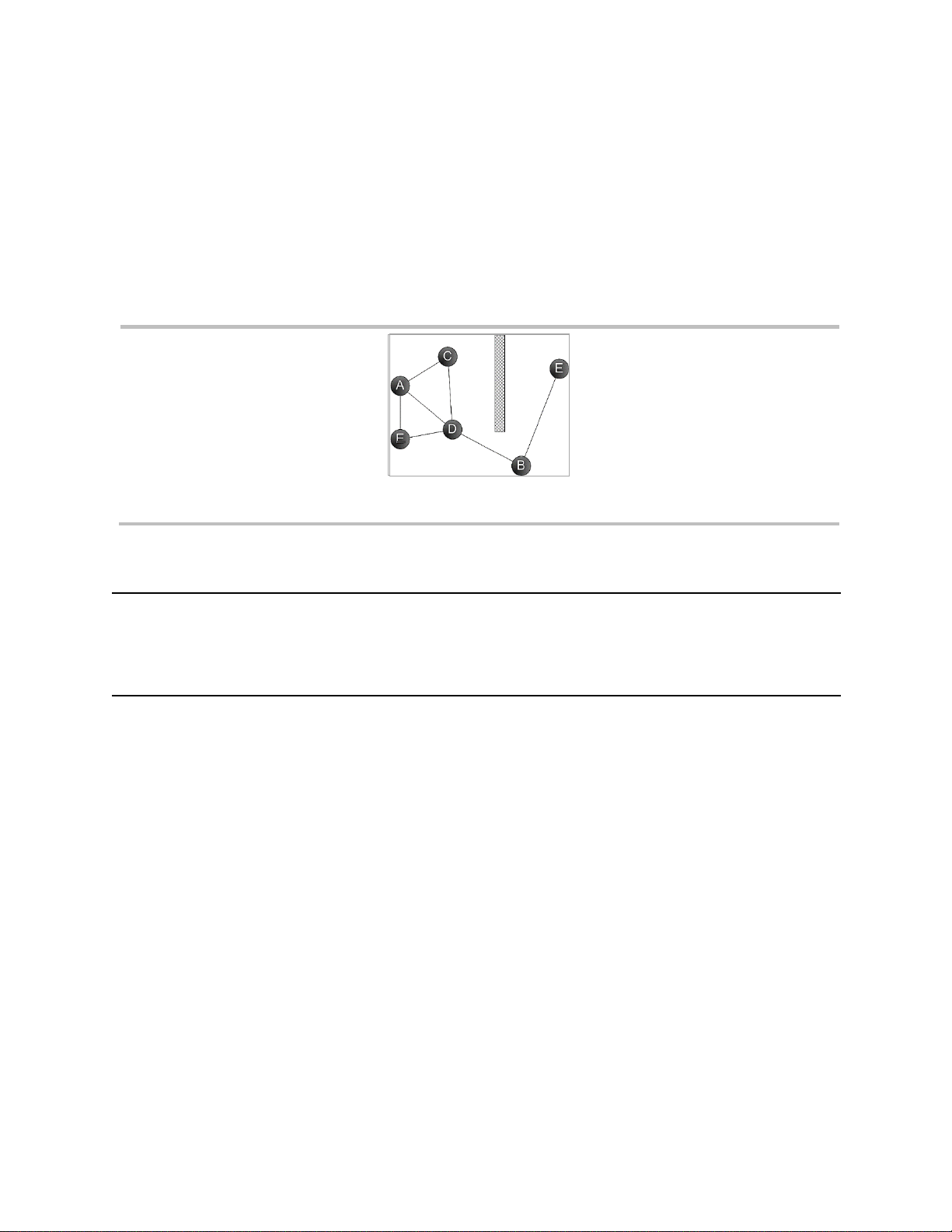
5
• When using LENS Wireless, ensure each instrument is assigned to the desired LENS group; create the
placement plan to account for each instrument being within range of at least one other instrument in its
group. Use the range guidelines supplied below (see Table 1.4) to maintain each connection type.
*Available when the iNet Now service has been activated and all to-be-monitored instruments have been activated for live
monitoring.
To achieve best performance for a unit that will use GPS, ensure the site provides large, open-sky access.
Units used in an indoor environment cannot receive the signal required for GPS functionality.
As needed, supervise the in-field placement of instruments (see chapter 6, "Operation").
Figure 1.1 Sample placement plan for instruments in a LENS group
Table 1.4 Range guidelines for LENS Wireless connections
Line-of-sight distance, maximum
Radius BZ1 to Radius BZ1
300 m (328 yd)
Radius BZ1 to Ventis Pro
100 m (109 yd)a
Radius BZ1 to RGX Gateway
300 m (328 yd)
a
Applies when a Ventis Pro instrument is positioned to face the other instrument.
Maintenance
The procedures defined below help to maintain instrument functionality and support operator safety. They
also help manage for the effects of sensor drift. Sensor drift is defined as a gradual shift in sensor output,
which causes an error in the displayed gas reading. The shift can be either positive or negative and is
typically caused by the conditions listed below.
• There are changes in environmental conditions such as temperature, pressure, humidity, or thermal
conductivity of the air.
• The sensor has cross sensitivity* to nontarget gases and has been directly exposed to one or more of
those gases, or is experiencing lingering, temporary effects from this type of exposure.
• The sensor has been zeroed or calibrated in an atmosphere that contains some concentration of the
sensor's target gas or some concentration of nontarget* gas to which the sensor responds.
• There are changes in the power state of a biased sensor. Biased sensors require continuous power
and may take a while to stabilize after being in a state of low or no power. Biased sensors installed in
the Safecore Module are powered only by the module's "backup battery" when the module is out of the
Radius Base or docking station. When the module is returned to the docking or Radius Base, there will
be a warm-up period.

6
*For more information about the cross sensitivities of nontarget gases see "Appendix A, Supplemental Information about Gases
and Sensors."
Industrial Scientific minimum-frequency recommendations for instrument maintenance are summarized
below in Table 1.4. These recommendations are provided to help support worker safety and are based on
field data, safe work procedures, industry best practices, and regulatory standards. Industrial Scientific is
not responsible for determining a company’s safety practices or establishing its safety policies, which may
be affected by the directives and recommendations of regulatory groups, environmental conditions,
operating conditions, instrument use patterns and exposure to gas, and other factors.
Settings
Settings control how an instrument will perform. They are used to support compliance with company safety
policy and applicable regulations, laws, and guidelines as issued by regulatory agencies and government or
industry groups.
Utilities
Maintenance procedures are known as "utilities." Utilities are used to test the instrument or its components
for functionality or performance, or to complete other maintenance tasks. Each utility is defined below.
Self-test.
The self-test checks the functionality of the instrument’s memory operations, battery, display screen, and
each alarm-signal type (audible and visual).
Bump Test* (or "functional test").
Bump testing is a functional test in which an instrument's installed sensors are to be briefly exposed to (or
“bumped” by) calibration gases in concentrations that are greater than the sensors’ low-alarm setpoints.
This will cause the instrument to go into low alarm and will indicate which sensors pass or fail this basic test
for response to gas.
Zero*.
Zeroing adjusts the sensors’ “baseline” readings, which become the points of comparison for subsequent
gas readings. It is a prerequisite for calibration. During zeroing, the installed sensors are to be exposed to
an air sample from a zero-grade-air cylinder or ambient air that is known to be clean air. If there are gases
in the air sample that are below the lowest alarm level, the instrument will read them as zero; its task is to
read the air sample as clean air. The user's task is to ensure the air is clean.
Calibration*.
Regular calibrations promote the accurate measurement of gas concentration values. During calibration, an
instrument’s installed sensors are to be exposed to their set concentrations of calibration gases. Based on
the sensors’ responses, the instrument will self-adjust to compensate for declining sensor sensitivity, which
occurs as the installed sensors are used or “consumed."
Note: After calibration, the span reserve percentage value for each sensor is displayed. An indicator of a sensor's remaining life,
when the value is less than 50%, the sensor will no longer pass calibration.
Docking.
When docked, instruments that are supported by iNet® Control or DSSAC (Docking Station Software
Admin Console) will be maintained for all scheduled bump tests and calibrations, synchronized for any
changes to settings, and upgraded for improvements from Industrial Scientific.
Other Maintenance.

7
The time-weighted average (TWA), short-term exposure limit (STEL), and peak readings can each be
"cleared." When any summary reading is cleared, its value is reset to zero and its time-related setting is
also reset to zero.
*Complete only in areas known to be nonhazardous.
Table 1.5 Recommended frequencies for instrument maintenance
Procedure
Recommended minimum frequency
Settings
Before first use, when an installed sensor is replaced, and as needed.
Zero
Before first use; thereafter, zero the instrument every two weeks or when sensor drift is observed.
Calibrationa
Before first use and monthly thereafter.
Bump testb
Before first use; thereafter, for sensors not operating on DualSense™, prior to each day’s use and,
for sensors operating on DualSense, as needed between monthly calibrations.
Self-testc
As needed.
a
Between regular calibrations, Industrial Scientific also recommends a calibration be performed immediately following each of these incidences:
the unit falls, is dropped, or experiences another significant impact; fails a bump test; has been repeatedly exposed to an over-range (positive
or negative) gas concentration; or its sensors are exposed to water or contaminants. A calibration is also recommended after the installation of
a new or replacement sensor.
b
If conditions do not permit daily bump testing, the procedure may be done less frequently based on instrument use, potential
exposure to gas, and environmental conditions as determined by company policy and local regulatory standards.
b
When redundant sensors are operating on DualSense technology, bump testing these sensors may be done less frequently based on
company safety policy.
c
The instrument performs a self-test during power on. When the instrument remains on, it will complete a self-test during each 12-hour period.
The self-test can also be completed on demand through settings.
Note: The use of calibration gases not provided by Industrial Scientific may void product warranties and limit potential liability claims.
Biased Sensors
The functionality of biased sensors is dependent on their receipt of continuous power. When their power
supply is interrupted, it is their nature to destabilize. This means a biased sensor needs time to restabilize
after its power supply is removed or depleted, then restored. Stabilization time varies depending on the
sensor type and the length of time it has been without power. Use the information and guidelines supplied
below to support the stability of biased sensors installed in the SafeCore Module.
• Install the SafeCore Module into a fully charged Radius Base.
• When the module is installed in the Radius Base, its biased sensors will be powered by the base’s
rechargeable battery pack* if the Radius BZ1 is or is not powered on. If the base’s battery pack is
depleted of charge, the sensors will draw power from the module’s backup battery.
• When the module is not installed in a Radius Base, its biased sensors will be powered by the module’s
backup battery to help maintain sensor stability.
When a biased sensor is in use and the Radius BZ1 emits a low battery warning or a low backup battery
warning, complete the steps noted below.

8
Low battery warning
Low backup battery warning
• Charge the Radius Base battery.
• Replace the SafeCore module’s backup
battery.
• Power on the instrument.
• Install the module in a fully charged Radius
BZ1.
• Allow up to 24 hours for the biased sensor to
stabilize.
• Power on the instrument.
• Allow up to 24 hours for the biased sensor to
stabilize.
The power requirements of biased sensors can exceed the setpoint for the low backup battery warning.
When a sensor’s required power exceeds what the backup battery can supply, the Radius BZ1 will indicate
a sensor error, so in some cases, the cause of sensor error for a biased sensor may need to be treated as
a low backup battery warning as described above.
See also “Care and Storage” below.
Remote Sampling
When sampling with a motorized pump and sampling line, Industrial Scientific recommends the following.
• Choose the tubing type based on the target gases. If the target gases are known, use Teflon-lined
tubing when sampling for these gases: chlorine (Cl2), chlorine dioxide (ClO2), hydrogen chloride (HCl),
and volatile organic compounds (VOCs). For other known target gases, urethane tubing or Teflon-lined
tubing may be used.
When the target gases are unknown, use Teflon-lined tubing.
• Know the length of the sample line as it is a factor in determining sampling time. A sample line may
consist of tubing, a probe, or a probe and tubing. It should also have a dust filter–water stop installed at
the line's end that will extend into the sample area. Sample-line length is defined as the distance from
the dust filter–water stop opening to the point where the line connects to the pump's inlet. Ensure
sample-line length does not exceed the pump's maximum draw.
• Before and after each air sample, perform a test of the full sampling line.
o Use a thumb to block the end of the sampling line at the water-stop opening. This should
cause a pump-fault alarm.
o Remove the thumb from the water-stop opening. After the alarm cycle completes, the pump
should resume normal operation.
Note: If a pump fault does not occur, check and correct for cracks or other damage, debris, and proper installation in
these areas: the sampling line and its connections, the pump's inlet cap and inlet barrel, and the dust filter-water stop
items at the end of the sampling line and inside the pump inlet barrel.
• Based on sample-line length, calculate the minimum time recommended for the air sample to reach the
instrument's sensors. As shown below, use a base time of 2 minutes, and add 2 seconds for each 30
cm (1 ') of line length. Watch the display screen for gas readings and, if present, allow them to stabilize
to determine the reading.

9
Table 1.6 Minimum sample time for common sample-line lengths
Sample-line length
Base time
(minutes)
+
Sample-line-length
factor
=
Minimum sample time
(mm:ss)
3.05 m (10 ')
2 min + (10 ' x 2 s)
=
02:20
6.10 m (20 ')
2 min
+
(20 ' x 2 s)
=
02:40
9.14 m (30 ')
2 min
+
(30 ' x 2 s)
=
03:00
12.10 m (40 ')
2 min
+
(40 ' x 2 s)
=
03:20
15.24 m (50 ')
2 min + (50 ' x 2 s)
=
03:40
18.29 m (60 ')
2 min + (60 ' x 2 s)
=
04:00
21.34 m (70 ')
2 min + (70 ' x 2 s)
=
04:20
24.38 m (80 ')
2 min + (80 ' x 2 s)
=
04:40
27.43 m (90 ')
2 min + (90 ' x 2 s)
=
05:00
30.48 m (100 ')
2 min + (100 ' x 2 s)
=
05:20
Care and Storage
Periodic inspection of the instrument can identify some care and service needs.
• Inspect dust and water barriers and replace them if visibly dirty or clogged.
• Connectors, including the SafeCore Module connector, can be cleaned using compressed air.
• The Radius Base can be wiped clean with a damp cloth. Isopropyl alcohol 70% can be used for
cleaning, but do not use acetone or other products as they may damage the plastic. Do not use
cleaning products that contain silicone as they can contaminate the sensors.
Note: Prolonged exposure to moisture may cause the equipment to experience slight coloration changes. These changes
do not impact the performance, integrity, or characteristics of the materials.
• Industrial Scientific recommends the SafeCore Module be stored in the Radius Base; this will help
support conservation of the module’s backup battery, a power source that maintains the module's clock
and is needed when biased sensor are installed.
Before long-term storage of the instrument or its base, fully charge the Radius Base factory-installed
battery pack. As indicated below, limit the storage duration based on the temperature range of the storage
area. These practices will support the unit's ability to receive a charge prior to operation.
Table 1.7 Storage temperature and duration for a fully charged unit
Storage temperature range
Maximum storage time
−20 °C to +5 °C (−4 °F to 41 °F)
up to 21 days
5 °C to 25 °C (41 °F to 77 °F)
up to 90 days
25 °C to 55°C (77 °F to 131 °F)
up to 21 days


2
Product Information
Instrument Overview
System Overview
Key Features
Compatibilities
Specifications
Instrument Overview
The Radius® BZ1 Area Monitor is a multigas area monitor (instrument) that can provide readings for up to
seven gases simultaneously. With its fifteen compatible sensors, the instrument is capable of monitoring for
oxygen and a variety of toxic gases and combustible gases. The Radius BZ1 is used outdoors and indoors
for applications that require a worker or worksite perimeter, a fence-line setup, a standalone unit, and
confined-space monitoring.
System Overview
The Radius BZ1 can be operated as a stand-alone gas-detection instrument for area monitoring. This is
suitable for applications where the goal is use a Radius BZ1 in a manner that will alert nearby workers to
gas hazards and provide optional, instructional messages for specific hazards.
When the goal is to wirelessly connect multiple Radius to monitor for an application like a fence-line setup,
LENS™ Wireless is available. It allows Radius BZ1 instruments to operate in a wirelessly connected LENS
group, where the instruments share their alarms and gas readings with one another. When one instrument
goes into alarm, the other instruments in the LENS group go into peer alarm. This promotes the visual or
audible awareness of alarms over a large geographic area. The LENS group can also include Ventis® Pro
Multi-Gas Monitors, for applications like confined-space monitoring, by wirelessly connecting an unmanned
Radius BZ1 to a worker who is equipped with a Ventis Pro.
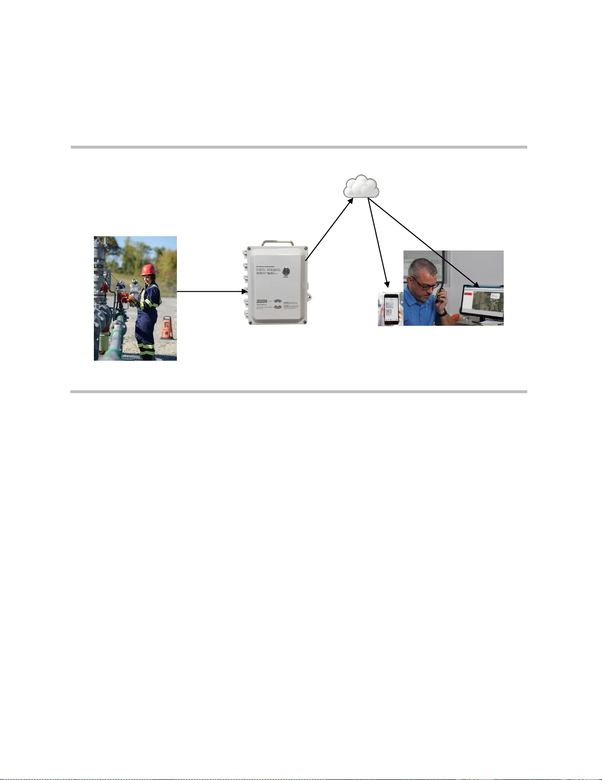
When the goal is to achieve all the above benefits and to gain a method for the live monitoring of all this
activity, a compatible gateway from Industrial Scientific can be deployed. The RGX™ Gateway facilitates
data exchange between compatible, enabled Industrial Scientific gas-detection instruments and iNet®. The
exchanged data are used to support the live-monitoring capabilities of iNet Now.
From a computer or smart-device, iNet Now users can learn about anything from instrument* gas readings
to gas alarms, man-down events, and panic alarms. iNet Now offers a mapped view of instrument status,
and the option to create subscription-based alerts to notify (via text or email) individual iNet Now users of
gas-detection and worker events for specific instruments.
This wirelessly connected, live-monitoring system, as depicted below, enhances quick responses and
preparedness for hazardous events.
12
Note: For applications that include both Radius and Ventis Pro instruments, a smart-device gateway** is
also available.
*Available when the iNet Now service has been activated and all to-be-monitored instruments have been activated for live
monitoring.
**Some restrictions apply.
iNet
Instrument data
RGX Gateway
iNet Now users (live monitoring
and subscription-based alerts)
Figure 2.1 System overview
Key Features
Modularity
The Radius BZ1 Area Monitor consists of the SafeCore® Module and Radius Base.
When installed in the Radius Base, the SafeCore Module, serves as the instrument's central processing
unit. It houses the gas sensors, electronics, firmware, data log, settings, wireless radio, clock and clock
battery, and the pump (aspirated instruments only). The module is in-field replaceable. It is also is
removable for maintenance and service—tasks that are to be performed in a nonhazardous area.
The Radius Base houses the long-life, extended-run-time, rechargeable battery pack that powers the
instrument. The Radius Base also serves as the user interface and comprises the instrument's buttons,
display, and visual and audible alarm-warning-indicator signals.
Power
When the instrument is not in use, the battery pack can be charged in a nonhazardous environment using
the product's power supply and power cord. When the instrument is in use, its charge can be maintained
using the product's compatible power-supply accessories* from Industrial Scientific.
*Some restrictions apply.
DualSenseTechnology
DualSense® Technology enables the use of redundant sensors, two installed sensors of the same type that
are DualSense capable. Paired DualSense sensors concurrently measure the target gas concentration in

13
the atmosphere. Using a proprietary algorithm, the instrument processes each sensor's data to display a
single gas reading, while maintaining data logs for each sensor and for the derived DualSense "virtual"
sensor.
Each paired sensor operates independently of its redundant sensor, so will revert to operate as a single
sensor in the event its paired sensor fails. This allows the instrument to continue operation while a
DualSense sensor is in failure.
LENS Wireless
Radius BZ1 instruments can be equipped with LENS Wireless, a long-range, power-efficient wireless mesh
network from Industrial Scientific. Any instrument that is not LENS-equipped at the time of manufacture can
be later upgraded by contacting Industrial Scientific or an authorized service center.
LENS functionality enables instrument-to-instrument, or peer-to-peer, communications. It uses a group
feature to facilitate the wireless connection of specific instruments. Each instrument is readily assigned to a
peer group through its settings.
LENS supports up to ten groups. Each group can accommodate from 2 to 25 equipment items. A group can
include Radius BZ1 Area Monitors, Ventis Pro Series instruments, and RGX Gateways.
When two or more gas detection instruments are set to perform in a LENS group—and each is within range
of any other instrument in that group—they share their alarms and gas readings. This allows in-field
personnel to learn of and respond to hazardous gas conditions that are detected by any instrument within a
group.
Data communicated using LENS Wireless are secured with the Industrial Scientific encryption key. LENS
also allows the customer to optionally use its own custom encryption key**. LENS functionality requires no
central controller, network configuration, or infrastructure.
iNet Now
When Radius instruments are wirelessly connected to a compatible gateway from Industrial Scientific, their
alarms and other data are sent to iNet to support the live-monitoring features of iNet Now. Part of this setup
requires activation of the iNet Now service. Instruments must be activated for live monitoring, which is done
through iNet’s iNet Now area. Instrument settings and wireless range guidelines also apply as described in
this “Product Manual”.
iNet Now provides the safety team with these and other live-monitoring features.
• Setup and receive (via SMS text, email, or both) detailed, subscription-based alerts that notify of gas-
detection and worker events.
• View a live-monitoring map.
• View instrument status summaries.
Messaging
Radius BZ1 instruments give the safety team a variety of options to provide instrument operators with
customized on-screen messages**. This includes a custom start-up message, which displays during the
power-on process. A unique instructional message, or "alarm action message", can be set for each of these
gas events for each sensor: gas present (low alarm and high alarm), STEL, and TWA. These messaging
options provide opportunities for the safety team to communicate specific instructions to the instrument
operator.
**Requires iNet® Control or DSSAC (Docking Station Software Admin Console) from Industrial Scientific.

14
Compatibilities
Batteries and Power Supplies
The battery pack that powers the Radius BZ1 Area Monitor is encased in the Radius Base. It is charged in
a nonhazardous environment using its dedicated power supply and power cord.
Table 2.1 Compatible batteries
Item
Purpose
Use restrictions
Radius Base
Encased battery pack
Powers the instrument.
Rechargeable only in areas that are known to be
nonhazardous.
Power supply and power
cord
Charges the encased battery
pack.
Use only in areas that are known to be nonhazardous.
SafeCore Module
Backup battery
Powers the module's clock;
powers any installed biased
sensors when the SafeCore
Module is not installed in a
Radius Base or docking station.
Replaceable only in areas that are known to be
nonhazardous.
The Radius BZ1 is compatible with two power-supply accessories from Industrial Scientific, which serve to
extend the instrument's run time while the instrument is in operation. Each has unique use restrictions and
run-time effects. Before using either power supply, read and understand its product manual, which includes
a required control drawing.
Table 2.2 Compatible power supplies
Power supply
Product manual part number
Intrinsically Safe Extended Run Time Power Supply
17158248
Extended Run Time Power Supply
17158358
Sensors
As depicted in Figure 2.2, up to six sensors can be installed, each in one or more specific locations inside
the SafeCore Module. To support ingress protection, use a compatible plug in place of any uninstalled
sensors as shown in locations 4 and 6.

15
4
Back of module
2
6
1
5
Front of module
3
Locations 3 or 4 only
Any location
LEL (methane)a 17156650-L
LEL (pentane)a 17156650-K
PID 17156650-R
Ammonia (NH3); 17156650-6
Carbon Monoxide (CO)*; 17156650-1
Carbon Monoxide, high range (CO); 17156650-H
Carbon Monoxide, low H2 interference (CO-low H
2
a
;
17156650-G
Carbon Monoxide and Hydrogen Sulfide (CO/H2S)a;
17156650-J
Chlorine (Cl2); 17156650-7
Hydrogen (H2); 17156650-C
Hydrogen Cyanide (HCN); 17156650-B
Hydrogen Sulfide (H2S)a; 17156650-2
Nitric Oxide (NO)b; 17156650-D
Nitrogen Dioxide (NO2)*; 17156650-4
Oxygen (O2)*; 17156650-3
Phosphine (PH3); 17156650-9
Sulfur dioxide (SO2)*; 17156650-5
Figure 2.2 Compatible sensors and installation locations
a
DualSense capable. When installing two of the same sensor type for DualSense operation, use the sensor-type compatible locations in these combinations
only: locations 1 and 2, locations 3 and 4, and locations 5 and 6. It is recommended that sensors operating on DualSense have manufacturing dates within
three months of each other (see "Mfg. date" YYYY-MM).
b
Biased sensor (see chapter 1, "Recommended Practices, Biased Sensors”).
Docking Station and Software
The SafeCore Module is compatible with the DSX™ Docking Station and is supported by iNet or DSSAC
software from Industrial Scientific.
Sample Tubing Kits
Industrial Scientific recommends the use of its Teflon-lined tubing kit (part number 18109206) when
sampling for these gases, which are susceptible to absorption by other types of tubing materials: Chlorine
(Cl2), Chlorine Dioxide (ClO2), Hydrogen Chloride (HCl), and Volatile Organic Compounds (VOCs). For
other target gases, the Teflon-lined tubing kit can be used as can the Urethane tubing kit (part number
18109207).

16
Specifications
Instrument
The Radius BZ1 takes gas readings every second and records readings-related data at its settable interval.
Data are stored in the instrument data log, which has these characteristics:
• Capacity for approximately 90 days of data for a unit that has six installed sensors and is set to record
data every ten seconds.
• Data storage for up to 60 alarm events, 30 error events, and 250 manual calibrations and bump tests.
Additional instrument specifications are provided below.
Table 2.3 Instrument specifications
Item
Description
Display
11.2 cm (4.4 ″) monochrome LCD
User interface buttons
Three: power button, left button, and right button
Alarmsa
Visual: red and blue LEDs
Audible: 108 dB at a distance of 1m (3.3 ′)
Dimensions
29 x 29 x 55 cm (11.5 x 11.5 x 21.5 ″)
Weight
7.5 kg (16.5 lb)
Ingress protection
IP66
Pump
With 0.3175 cm (0.125 ") inside diameter sample tubing, sustains a continuous sample
draw for up to 30.48 m (100 ')
Operating temperature rangeb
-20 °C to +55 °C (-4 °F to +131 °F)
Operating humidity rangeb
15−95% relative humidity (RH) noncondensing (continuous)
Storage temperature rangec
-20 °C to +55 °C (-4 °F to +131 °F)
Pressure range
1 atm ± 0.2 atm
a
May vary based on in-field conditions.
b
Sensor temperature and humidity ranges may differ from those of the instrument (see "Table 2.5 Sensor specifications").
c
Maximum storage duration is based on the temperature of the storage environment (see “Table 1.7 Storage temperature and duration for a fully charged unit”).
Batteries
Provided below are battery specifications, which include run time, charge time, charging temperature
requirements, and expected lifetime.
Table 2.4 Battery specifications
Battery
Radius Base battery
pack
SafeCore Module battery
Battery type
Nickel Metal Hydride
Lithium Thionyl Chloride (Li-SOCl2)
Battery lifetime
2 years
2+ yearsc
Run timea
168 hours
—
Battery charge time
Less than 8 hours
—

17
Table 2.4 Battery specifications
Battery
Radius Base battery
pack
SafeCore Module battery
Charging cycles
1000 cycles
—
Battery charge temperatureb
0 − 50 °C (32 − 122 °F)
—
Nominal voltage
6.0 VDC
3.6 VDC
Nominal capacity
12.0 Ah
1.1 Ah
Nominal power
72.0 Wh
4.0 Wh
a
Approximate run time for a fully charged battery powering a diffusion unit that is operating at room temperature (25 °C [77 °F]) with CO, H2S, O2, and LEL
sensors installed, has the wireless option enabled, and experiences 10 minutes of high alarm per day.
b
Battery charging is suspended in temperatures below 0 °C (32 °F) and above 50 °C (122 °F).
c
The use of biased sensors may decrease the battery lifetime.
Sensors
Provided below are specifications for each sensor, which include properties, installation locations, operating
conditions, and performance data.

18
Table 2.5 Sensor specifications
Gas type (abbreviation)
Part number
Ammonia (NH3)
Carbon Monoxide (CO)
17156650-6
17156650-1
Properties
Category
Toxic and combustible
Toxic
Technology
Electrochemical
Electrochemical
DualSense capable
No
Yes
Installation locations
Any
Any
Operating conditions
Temperature rangea
-20 to +40 °C
(-4 to +104 °F)
-20 to +50 °C
(-4 to +122 °F)
RH rangea
15–95%
15–90%
Performance
Sensitivity
Measurement range
0–500 ppm
0–1500 ppm
Measurement resolution
1 ppm
1 ppm
Accuracyb
Calibration gas and
concentration
50 ppm NH3
100 ppm CO
Accuracy at time and
temperature of calibration
± 11% (0–50 ppm)
± 13% (51–500 ppm)
± 5%
Accuracy over sensor’s full
temperature range
± 15%
± 15%
Response Time
T50
26 s
8 s
T90
85 s
19 s

19
Table 2.5 Sensor specifications
Gas type (abbreviation)
Part number
Carbon Monoxide, high range (CO)
Carbon Monoxide, low Hydrogen
interference
CO-Low H2
17156650-H
17156650-G
Properties
Category
Toxic
Toxic
Technology
Electrochemical
Electrochemical
DualSense capable
No
Yes
Installation locations
Any
Any
Operating conditions
Temperature rangea
-20 to +50 °C
(-4 to +122 °F)
-20 to +50 °C
(-4 to +122 °F)
RH rangea
15–90%
15–90%
Performance
Sensitivity
Measurement range
0–9999 ppm
0–1000 ppm
Measurement resolution
1 ppm
1 ppm
Accuracyb
Calibration gas and
concentration
100 ppm CO
100 ppm CO
Accuracy at time and
temperature of calibration
± 6.0%
± 6.0%
Accuracy over sensor’s full
temperature range
± 15.0%
± 15.0%
Response Time
T50
9 s
9 s
T90
18 s
20 s

20
Table 2.5 Sensor specifications
Gas type (abbreviation)
Part number
Carbon Monoxide and Hydrogen Sulfide (CO and H2S)
17156650-J
Properties
Category
Toxic
Technology
Electrochemical
DualSense capable
Yes
Installation locations
Any
Operating conditions
CO
H2S
Temperature rangea
-20 to +50 °C
(-4 to +122 °F)
-20 to +55°C
(-4 to +131°F)
RH rangea
15–90%
15–95%
Performance
Sensitivity
Measurement range
0–1500 ppm
0–500 ppm
Measurement resolution
1 ppm
0.1 ppm
Accuracyb
Calibration gas and
concentration
100 ppm CO
25 ppm H2S
Accuracy at time and
temperature of calibration
± 5%
± 9%
Accuracy over sensor’s full
temperature range
± 15%
± 15%
Response Time
T50
13 s
11 s
T90
33 s
21 s
 Loading...