


P/N 1709-5753
Rev 9
Printed September 2011
Specifications Subject to Change
1001 Oakdale Road, Oakdale, PA 15071-1500
(412) 788-4353 • Toll Free 1-800-DETECTS
FAX 412-788-8353 • Service Dept. 1-888-788-4353
Multi-Gas Monitor
Instruction
Manual
GUARANTEED.
FOR LIFE.

O U R M I S S I O N
Preserving human life on,
above and below the earth
Delivering highest quality,
best customer service …
every transaction, every time

Dear Valued Customer,
Thank you for buying and using Industrial Scientific’s
iTX Multi-Gas Monitor.
Your iTX can be relied upon for dependable service, day
after day. It has been designed, manufactured, tested and
proven under the most scrutinizing conditions possible.
With the minimal care and maintenance described in this
Instruction Manual, it will provide you with years of
reliable monitoring.
I am most concerned that you be pleased with the
performance of your iTX in the months and years ahead.
I urge you to call us with any questions or comments you
may have. Often times a phone call and a question can
save you hours of frustration. Please never hesitate to
contact me at 1-800-DETECTS (338-3287).
All of us at Industrial Scientific appreciate the opportunity
to serve you.
Sincerely,
Kent D. McElhattan
Chairman
Industrial Scientific Corporation

3
W
ARNINGS ANDCAUTIONARYSTATEMENTS
Failure to perform certain procedures or note certain conditions may
impair the performance of the instrument. For maximum safety and
performance, please read and follow the procedures and conditions
outlined below.
Oxygen deficient atmospheres may cause combustible gas readings to
be lower than actual concentrations.
Oxygen enriched atmospheres may cause combustible gas reading to
be higher than actual concentrations.
Verify the calibration of the combustible gas sensor after any incident
where the combustible gas content has caused the instrument to latch in
the OVER-RANGE alarm condition.
Silicone compound vapors or other known contaminants may affect the
combustible gas sensor and cause readings of combustible gas to be lower
than actual gas concentrations. If the instrument has been used in an area
where silicone vapors were present, always calibrate the instrument before
next use to ensure accurate measurements.
Sensor openings and water barriers must be kept clean. Obstruction of
the sensor openings and/or contamination of the water barriers may cause
readings to be lower than actual gas concentrations.
Sudden changes in atmospheric pressure may cause temporary
fluctuations in the oxygen reading.
Recharge battery only in a non-hazardous location.
Instrument is tested for intrinsic safety in explosive gas/air (21%
oxygen) mixtures only.
CAUTION: High Over-Range (+OR) combustible gas readings may
indicate an explosive concentration of combustible gas. This condition
locks the iTX in high alarm and must be manually reset by clearing the
gas hazard and turning the iTX off and on again.
iTX units equipped with bias sensors will self discharge a fully charged
battery in approximately four days. Because of this, bias sensor equipped
units are shipped without the battery installed. Upon receipt, install the
battery and allow the bias sensors to stabilize for 24 hours. Always store
bias sensor equipped iTX units on the appropriate charger (lithium-ion
versions only).
The use of leather cases can produce inaccurate readings with diffusion
(non-aspirated) gas detection instruments for specific monitoring applications.
Leather cases should be used ONLY as carrying cases, and NOT for
continuous monitoring, with diffusion instruments configured to measure
gases other than O2, CO, CO2, H2S, and combustible gases (LEL/CH4).
!
!
!
!
!
!
!
!
!
!
!
2
Multi-Gas
Monitor
W
ARNINGS AND
C
AUTIONARYSTATEMENTS
................................................3
U
NPACKINGTHEINSTRUMENT
....................................................................6
V
IEW OFINSTRUMENT
................................................................................7
I
NSTRUMENTOPERATION
............................................................................8
Turning the iTX On and Off..........................................................8
Gas Reading Mode.........................................................................8
V
IEWING THE
iTX O
PERATINGMODES
.......................................................9
PPM Explosive Gas Reading .........................................................9
Zeroing and Calibration .................................................................9
Peak Readings ..............................................................................10
STEL Readings.............................................................................10
TWA Readings..............................................................................10
Pause Datalog...............................................................................10
Resetting Datalogging Session.....................................................11
Datalog Session ............................................................................11
Last Calibration/Calibration Due .................................................11
Time/Date/Temperature................................................................12
User Identification........................................................................12
Site Identification .........................................................................13
C
ONFIGURING THE
iTX’SC
USTOMSETTINGS
...........................................13
Security Code ...............................................................................14
Security Features..........................................................................14
Alarm Configuration ....................................................................15
Sensor Calibration Gas.................................................................15
Quick Calibration .........................................................................16
Zero Sensors.................................................................................16
Zero Sensors On Startup ..............................................................16
Allow Sensor Zeroing in the Field...............................................16
Allow Calibration in the Field .....................................................16
Numeric Display ..........................................................................17
Peaks.............................................................................................17
Allow Viewing Peak Readings in Field.......................................17
Allow Viewing STEL/TWA Reading in Field .............................17
TWA .............................................................................................17
Non-Latching................................................................................18
Confidence Beep ..........................................................................18
Data Logging Configuration ........................................................18
Allow Over-Writing of Data................................................18
Log Data On Alarm Only....................................................19
Allow Manual Pause/Resume in Field................................19
Data Logging Interval..........................................................19
Clear Data Logging Memory ..............................................19
Calibration Dates..........................................................................19
Next Calibration Dates.................................................................20
Allow Viewing Calibration Dates................................................20
Current Date Screen .....................................................................20
Allow Viewing Date and Time in Field.......................................20
Backlight Shut-Off .......................................................................21
Active User...................................................................................21
Active Site....................................................................................22
Allow Changing of Site and User In Field ..................................22
Allow Viewing Site and User in Field.........................................22
Allow Viewing Combustible PPM...............................................23
C
ALIBRATING THE
iTX .............................................................................23
Standard Calibration.....................................................................24
Quick Calibration .........................................................................25
R
EMOTESAMPLING
..................................................................................25
Using the iSP (Motorized Sampling Pump).................................26
Using the Hand Aspirated Pump..................................................26
M
AINTENANCE
....................................................................................27-29
S
PECIFICATIONS
...................................................................................29-30
E
XPLODEDVIEW
& R
EPLACEMENTPARTS
...........................................31-33
W
ARRANTY
.............................................................................................34
ATEX D
ECLARATION
...............................................................................36
TABLE OF CONTENTS

54
W
ARNINGS AND
C
AUTIONARY
S
TATEMENTS
WARNING (UL CLASSIFICATION, DEMKO CERTIFICATION AND CSA
CERTIFICATION ONLY):
USE ONLY WITH RECHARGEABLE BATTERY PACK P/N 1715-3303, P/N 17088618 OR 4.5V ALKALINE BATTERY PACK P/N 1708-9376 CONTAINING THREE
IDENTICAL ALKALINE CELLS FROM THE FOLLOWING LIST: DURACELL
MN1500 OR RAYOVAC LR6. DO NOT MIX BATTERIES FROM DIFFERENT
MANUFACTURERS. REPLACE ALL BATTERIES AT THE
SAME TIME.
THE FOLLOWING ARE TO BE PERFORMED IN NON-HAZARDOUS
LOCATIONS ONLY: RECHARGE Li BATTERY PACK, CHANGE Li BATTERY
PACK, CHANGE ALKALINE BATTERY PACK, REPLACE ALKALINE CELLS,
SERVICE UNIT OR USE COMMUNICATION PORT.
DO NOT USE THE ITX IN OXYGEN ENRICHED ATMOSPHERES.
WARNING (MSHA APPROVAL ONLY):
USE ONLY WITH RECHARGEABLE BATTERY PACK P/N 1715-3290, P/N 17088618 OR 4.5V ALKALINE BATTERY PACK P/N 1708-9376 CONTAINING THREE
IDENTICAL ALKALINE CELLS FROM THEFOLLOWING LIST: DURACELL
MN1500 OR RAYOVAC LR6. DO NOT MIX BATTERIES FROM DIFFERENT
MANUFACTURERS. REPLACE ALL BATTERIES AT THE SAME TIME.
P/N 1715-3290 AND P/N 1708-8618 LI-ION RECHARGEABLE PACKS ARE NOT
TO BE REPLACED BY THE USER. CHARGE IN FRESH AIR ONLY.
THE FOLLOWING ARE TO BE PERFORMED IN NON-HAZARDOUS
LOCATIONS ONLY: RECHARGE Li BATTERY PACK, CHANGE ALKALINE
BATTERY PACK, REPLACE ALKALINE CELLS, SERVICE UNIT OR USE
COMMUNICATION PORT.
DO NOT USE THE ITX IN OXYGEN ENRICHED ATMOSPHERES.
CAUTION (UL CLASSIFICATION, MSHA APPROVAL, AND CSA
CERTIFICATION ONLY):
JACK FOR USE ONLY WITH INDUSTRIAL SCIENTIFIC EXTERNALALARM,
P/N 1810-1154 OR VIBRATING ALARM, P/N 1810-2146 ONLY.
CANADIAN STANDARDS ASSOCIATION (CSA) HAS ASSESSED ONLY THE
COMBUSTIBLE GAS DETECTION PORTION OF THIS INSTRUMENT FOR
PERFORMANCE.
CAUTION: BEFORE EACH DAY'S USAGE SENSITIVITY MUST BE TESTED
ON A KNOWN CONCENTRATION OF PENTANE OR METHANE EQUIVALENT TO
25-50% OF FULL SCALE CONCENTRATION. ACCURACY MUST BE WITHIN -0+20% OF ACTUAL. ACCURACY MAY BE CORRECTED BY REFERING TO
SECTION 5 OF THE INSTRUCTION MANUAL.
CAUTION: ANY RAPID UP-SCALE READING FOLLOWED BY A DECLINING
OR ERRATIC READING MAY INDICATE A GAS CONCENTRATION BEYOND
UPPER SCALE LIMIT WHICH MAY BE HAZARDOUS.
!
W
ARNINGS AND
C
AUTIONARY
S
TATEMENTS
READ AND FULLY UNDERSTAND THE ENTIRE INSTRUCTION MANUAL
AND THIS INSTRUCTION SHEET BEFORE USING OR SERVICING THE MODEL
ITX.
S'ASSURER DE BIEN LIRE ET DE BIEN COMPRENDRE TOUTES LES
INSTRUCTIONS DU MANUEL ET DE CE FEUILLET AVANT D'UTILISER ET DE
PROCÉDER AU DÉPANNAGE DU MODÈLE ITX.
OBSERVE ALL LAWS AND REGULATIONS OF THE LOCAL AUTHORITY IN
REGARDS TO BATTERY DISPOSAL.
THE MODEL ITX MULTI-GAS MONITOR (P/N 1810-4307) AND MODEL ISP
SAMPLE PUMP (P/N 1810-4646) COMPLIES WITH EUROPEAN ATEX
DIRECTIVE 94/9/EC AND EMC DIRECTIVE 89/336/EEC, AMENDED BY
DIRECTIVES 92/31/EEC AND 93/68/EEC.
THE MODEL ITX MULTI-GAS MONITOR (P/N 1810-4307) AND MODEL ISP
SAMPLE PUMP (P/N 1810-4646) IS CONSTRUCTED WITH REFERENCE TO
PUBLISHED STANDARDS OF DIRECTIVE 72/23/EEC, TO ELIMINATE
ELECTRICAL RISKS AND FULFILL 1.2.7 OF ANNEX II OF DIRECTIVE 94/9/EC
WARNING: SUBSTITUTION OF COMPONENTS MAY IMPAIR INTRINSIC
SAFETY AND MAY CAUSE AN UNSAFE CONDITION!
AVERTISSEMENT: LA SUBSTITUTION DE COMPOSANTS PEUT
COMPROMETTRE LA SÉCURITÉ INTRINSÈQUE!
PERFORMANCE CLAIMS ARE BASED UPON THE USE OF BATTERIES
WHICH HAVE AN ADEQUATE CHARGE AND ADEQUATE AIR FLOW
SAMPLING.
ANY LOW BATTERY INDICATION BY THE MODEL ITX, CAUTIONS THE
USER THAT THE BATTERIES INSTALLED DO NOT HAVE AN ADEQUATE
CHARGE, AND THAT THE USER SHOULD REPLACE THE BATTERIES, WITH
BATTERIES KNOWN TO HAVE AN ADEQUATE CHARGE, IN A
NONHAZARDOUS AREA, TO AVOID THE RISK OF AN EXPLOSION.
ANY INDICATION BY THE MODEL ISP SHOWING THAT A LOW FLOW OR
BLOCKAGE CONDITION EXISTS CAUTIONS THE USER THAT THE AIR FLOW
SAMPLING IS INADEQUATE AND THAT THE USER SHOULD ENSURE THAT
THE MODEL ISP HAS ADEQUATE AIR FLOW SAMPLING BEFORE
CONTINUING USE.
THE MODEL ITX IS CERTIFIED FOR USE WITHIN AN AMBIENT
TEMPERATURE RANGE OF -20ºC TO 40ºC ONLY.
!
!
!
!
!
!
!
!
!
!
!
!
!
!
!
!
!
!
!
!
ATTENTION
LE JACK DOIT ÊTRE UTILISÉ SEULEMENT AVEC UNE ALARME EXTERNE
INDUSTRIAL SCIENTIFIC N/P 1810-1154 OU UNE ALARME À VIBRATIONS N/P
1810-2146.
L'ASSOCIATION CANADIENNE DE NORMALISATION (CSA) A ÉVALUÉ
UNIQUEMENT LA PERFORMANCE DELA PORTION DÉTECTION DE GAZ
COMBUSTIBLES DE CET APPARELL.
!
!
76
U
NPACKING THE
I
NSTRUMENT
The shipping box should contain the following items.
Account for each item before discarding the box.
QUANTITY P
ART NUMBER DESCRIPTION
1 18104307 iTX Multi-Gas Monitor
1 17095753 iTX Instruction Manual
1 18104661 Nylon Carrying Case
1 17092339 Calibration Cup
1 17093659 Polyurethane Tubing
1 17095746 Maintenance Tool
After unpacking, if any listed item is missing, contact
either your local distributor of Industrial Scientific
products, or call Industrial Scientific Corporation at 1-800DETECTS (338-3287) in the United States and Canada, or
412-788-4353.
WARNING: iTX units equipped with bias sensors
will self discharge a fully charged
battery in approximately four days.
Because of this, bias sensor equipped
units are shipped without the battery
installed. Upon receipt, install the
battery and allow the bias sensors to
stabilize for 24-52 hours. Always
store bias sensor equipped iTX units
on the appropriate charger (lithiumion versions only). It is not
recommended to use alkaline
batteries in instruments with bias
sensors.
!
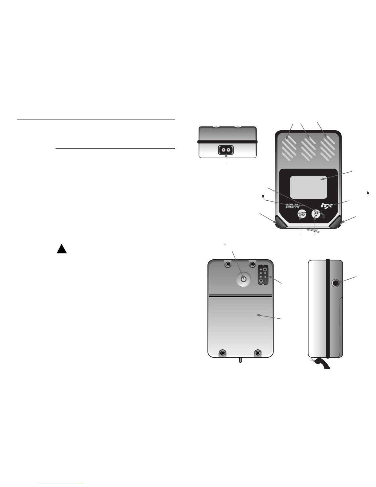
PPM PPMPPM
PPM LEL/CH4%VOL
Unmarked Key
Unmarked
Key
Audible Alarm
Sampling Pump Contact
Visual Alarm
Visual Alarm
Enter/Backlight Key
On/Off Mode Key
Sensor Openings
Display
External
Alarm
Jack
Charger/
Datalink
Connector
Battery
Cover
i
-Button
®
Contact
BOTTOM
FRONT
BACK
SIDE
98
I
NSTRUMENT
O
PERATION
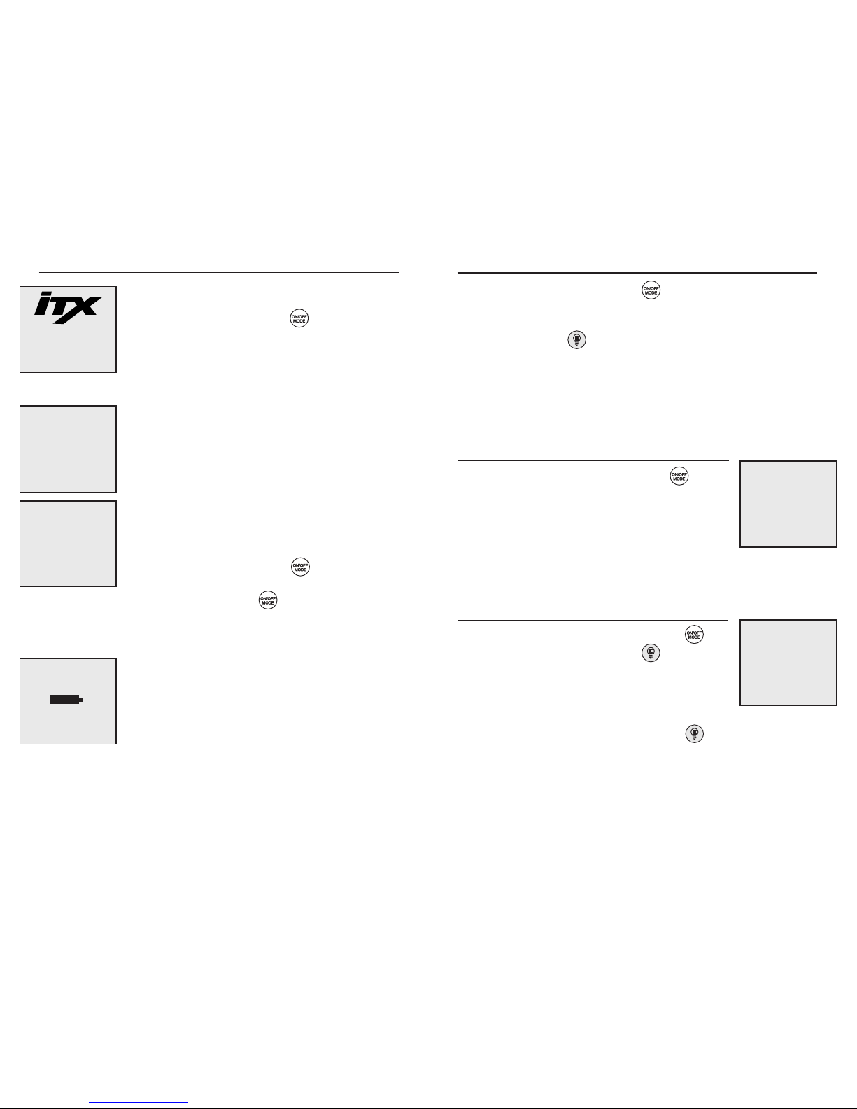
TURNING THE iTX ON AND OFF
To turn the iTX on, press and hold until the
instrument emits a short beep and the iTX welcome screen
appears on the display. The current revision of instrument
operating software is shown below the instrument model
name.
Revision 1.0
After the iTX warm-up screen, the display will identify
any new sensors installed which have not been calibrated
in the instrument. If this screen appears, the instrument
must be calibrated prior to further use. If the system clock
has not been set, you will be prompted to do so.
Prior to entering the normal operating mode, the iTX
display will show the type of each sensor installed in the
instrument along with a brief countdown timer until
normal gas readings appear.
To turn the iTX off, press and hold at any time
during operation until the instrument display shows
RELEASE. After releasing the instrument’s display
will blank and all operation will cease.
GAS READING MODE
In the Gas Reading Mode the iTX will show the type of
each sensor currently installed with the corresponding gas
concentration shown directly underneath it. A battery
status indicator is shown in the center of the display. As
the instrument battery life is reduced, the shaded area of
the battery indicator will clear until the instrument reaches
the low battery condition. With 15 minutes of battery life
left, a low battery condition occurs. The instrument will
make a periodic tone alerting the user that the battery
needs charged or replaced. If a preset gas alarm level is
exceeded for either low, high, STEL or TWA, the iTX will
activate audible and visual alarms and the corresponding
gas display will flash.
V
IEWING THE
iTX O
PERATINGMODES
PPM EXPLOSIVE GAS READING
If the ppm explosive feature is enabled, press until
“PPM EXP” appears. This screen will display the current
concentration of explosive gas in parts per million (ppm)
in 50 ppm intervals up to 10,000 ppm. If any gas reading
increases to a level exceeding the low alarm set-points, the
instrument will automatically return to the gas reading
mode.
New CO2
Sensors NH3
Installed CO
O2
H2S
E to Continue
CO SO2 H2S
10
O2 CL2 LEL
CO SO2 H2S
O 0.0 0
O2 Cl2 LEL
20.9 0.0 0
PPM EXP
1000
During Normal Operation, pressing the will scroll
the instrument through all of the operating modes that
have been enabled. While scrolling through the modes of
operation, pressing the when prompted access the
desired functions. To add or remove items from the
operating modes, the user must enable/disable the features
through the iTX configuration settings. Accessing these
custom settings is described in the Configuring iTX’s
Custom Section on page 11.
Zero Sensors
Press E to Zero
ZEROING AND CALIBRATION
If the zero and calibrate feature is enabled, press
until “Zero Sensors” appears. Pressing while this
screen is displayed will activate the instrument’s 20
second ZEROING sequence. This resets the current
instrument reading and reference point to zero and
calibrates the oxygen sensor to 20.9% in ambient air.
After the zeroing sequence is complete, pressing will
allow you to perform a span calibration to adjust and
ensure the accuracy of the instrument, see Calibrating the
iTX, page 21.

1110
PEAK READINGS
If the peak hold feature is enabled, press until
“PEAKS” appears. The peak reading displayed represents
the highest toxic and explosive gas concentration and the
lowest oxygen concentration measured since the peak
reading was last cleared from memory. To clear and reset
the peak readings, press and release while the peak
reading is displayed.
STEL READINGS
If the iTX STEL and TWA features are enabled press
until “STEL” appears. This screen will display the current
15 minute short term exposure limit (STEL) average
readings for toxic gases measured since these readings
were last cleared and reset.
TWA R
EADINGS
If the TWA feature is enabled, pressing once at the
STEL screen will display the TWA screen. This mode
displays the current time weighted average (TWA)
readings of the toxic gas sensors since they were last
reset. To reset STEL/TWA values, see Resetting
Datalogging Session, page 8.
PAUSE DATALOG
If the iTX datalogging and pause datalogging functions
are enabled, press until “Data Logging Paused”
appears. The Pause/Datalog screen allows the user to
temporarily stop the instrument from logging data.
Datalogging may be paused or resumed by pressing
while this screen is displayed. In normal operation the
video tape icon will flash while datalogging is enabled.
CO SO2 H2S
38 10.6 13
PEAKS
E to Clear
O2 CL2 LEL
18.6 1.6 8
CO SO2 H2S
10 0.8 3
STEL
CL2
1.6
CO SO2 H2S
5 0.8 3
TWA
CL2
0.6
RESETTING DATALOGGING SESSION
If the datalogging features are enabled, press until
“Start New Datalog Session” appears. Pressing
while this screen is displayed will start a new datalogging
session in the instrument’s memory. Starting a new
session automatically resets all STEL and TWA readings
in the instrument, if they have been enabled. When a new
session has begun, the session start time and date along
with the data recording interval will be stamped in the
instrument’s memory so that they can be retrieved at a
later date.
DATALOG SESSION
If the datalogging functions are enabled, press until
“Datalog Session” appears. This screen will show the
elapsed time in the current datalogging session, the
amount of datalogging time remaining until the
instrument’s memory is full and the instrument’s current
recording interval in seconds. When the memory is
nearing the end of its storage capacity, care should be
taken to download data to a PC, the DS1000 Docking
Station, or the DS2, to ensure that critical survey data is
not lost.
L
AST CALIBRATION
/CALIBRATION DUE
If the last calibration and calibration date due functions are
enabled press until “Instrument Calibration Due”
appears. The iTX will display the date of the last
calibration or the date the instrument is next due to be
calibrated based on the users choice and selected time
interval. The calibration date will be automatically
updated each time the instrument is calibrated (and every
sensor passes) either manually or when using the DS1000
or DS2 Docking Stations.
Data Logging
Paused
E To Resume
StartNew
Datalog
Session
Press E For New
Datalog Session
Elapsed Time
10:24
Remaining Time
2:23
Record Interval
300 Sec
Calibration
Dates
Due
08/12/01

SITE IDENTIFICATION
Press until “Active Site” appears. Monitoring site
location codes can be entered into the instrument’s
datalogging memory to correspond to measured gas
concentrations in the same manner as the user
identification codes. Pressing the while in this mode
and following the on screen instructions will allow the
current site ID to be selected from memory
• Pressing , allows the user to select a site name from a list
previously programmed into the instrument’s memory through the
instrument configuration menus. Use the down arrow hidden key
to scroll through the names, and the to select the desired site
name.
• Pressing the up-arrow hidden key allows the user to key ID
information in through the instrument keypad. Use the two hidden
arrow keys to scroll through available characters, and the to
select your character. Once the desired site name is entered, press
and hold the to accept it.
• Pressing the down-arrow hidden key allows the user to enter ID
information automatically with an iButton memory device. When
prompted, press the to read the iButton. After pressed, the
user has 5 seconds to press their iButton onto the contact located
on the back of the instrument (see page 5). After 5 seconds if no
iButton is detected, the instrument will beep and let you know it
failed reading the iButton. It will then go back to the initial Active
Site screen.
13
12
TIME/DATE /TEMPERATURE
If the time/date/temperature function is enabled, press
until today’s date appears. The iTX will display the
current time and date along with the current temperature
(inside the iTX) in degrees Fahrenheit and Celsius.
Although the current temperature reading can be a useful
tool, it should not be relied upon to provide instantaneous
temperature measurements. The temperature sensor will
only be accurate after the instrument has had time to adjust
to the environment. This typically will take several
minutes and in extreme temperature conditions may take
up to one-half hour.
USER IDENTIFICATION
Press until “Active User” appears. This screen
allows the current user’s name, identification code, or
number to be recorded into the instruments datalogging
memory. The user indentification can be entered in one of
three ways. Pressing the while in this mode and
following the on screen instructions will allow the current
user ID to be selected.
• Pressing , allows the user to select a user name from a list
previously programmed into the instrument’s memory through the
instrument configuration menus. Use the down arrow hidden key to
scroll through the names, and the to select the desired name.
• Pressing the up-arrow hidden key allows the user to key ID
information in through the instrument keypad. Use the two hidden
arrow keys to scroll through available characters, and the to
select your character. Once the desired user name is entered, press
and hold the to accept it.
• Pressing the down-arrow hidden key allows the user to enter ID
information automatically with an iButton memory device. When
prompted, press the to read the iButton. After pressed, the
user has 5 seconds to press their iButton onto the contact located on
the back of the instrument (see page 5). After 5 seconds if no
iButton is detected, the instrument will beep and let you know it
failed reading the iButton. It will then go back to the Initial Active
User screen.
14 March 2002
11:45 AM
72F 22 C
Active User
None
E To Change
Active Site
None
E To Change
C
ONFIGURING
iTX’SC
USTOMSETTINGS
The iTX Multi-Gas monitor has many user configurable
options and features. These feature may be accessed
through the configuration software and a PC, the DS1000
or DS2 Docking stations, or adjusted manually by pressing
the and hidden keys (see page 5)
simultaneously during the warm-up cycle when the count
down timer is displayed. Configuring your iTX is very
intuitive. Every option is highlighted on the display.
CO SO2 H2S
10
O2 CL2 LEL

15
14
In General:
• Pressing or will step you through the modes
or set a value.
• Pressing selects a function or accepts (saves) a
value.
• Pressing moves you backwards in the
configuration or steps you completely out of set up to
the “Gas Readings Mode.”
SECURITY CODE
Once the configuration mode has been entered, the
instrument will prompt you to enter the 3-digit security
access code if this feature has been enabled. If the
security code feature is activated in the instrument no
configuration changes can be made to the iTX without
entering the proper security code. The security code is
entered by pressing and to scroll through the
digits from 0 to 9. Pressing will shift the display
cursor to the next digit. Once the code has been entered
successfully, press to accept the value. The iTX
display will step to the next available configuration screen
if the proper code has been entered.
SECURITY FEATURES
If no security code has been established, the first
configuration screen you will view is “Security Features.”
Pressing allows you to configure a custom code.
You will then see “Change Setup Mode Security Code”
prompting you to press to change. Using the
and keys you can set the code, use to verify the
number, and hold to exit.
Enter Security
Code
or to Change
Mode to Select
Field
E To Accept
Alarm
Configuration
E to Change
Security
Features
E to Configure
ALARM CONFIGURATION
The “Alarm Configuruation” mode allows you to change
alarm set values for each sensor installed. Pressing the
will enter you into this menu item. All present gas sensors
appear on the screen. The hidden arrow keys allow you to
scroll to the different gas types. Pressing the will
select the highlighted gas sensor. Once a gas type is
selected, the hidden down arrow key allows you to select
which alarm type to change. Pressing the again will
select the alarm type and display the currently
programmed value. Using the two hidden arrow keys, the
alarm set points can be adjusted up or down. Once the
desired value is met, press the to accept it. Once
accepted, you can scroll to the next alarm type you want
to change, or press the to select a new gas sensor. If
no more changes are required, pressing the again will
bring you to the “Save Configuration Screen”.
saves the new alarm settings, while aborts all
changes.
SENSOR CALIBRATION GAS
The “Sensor Calibration Gas” mode allows you the option
of changing the concentrations of the calibration gases. To
change concentrations, simply press the to enter this
mode. Once entered, the user can use the hidden down
arrow key to select which calibration gas is to be changed.
When the desired gas is highlighted press to change
the concentration. Using the hidden arrow keys, you can
adjust the concentration up or down. Pressing will
accept the new calibration gas concentration. Once
accepted, you can select the next calibration gas
concentration to change. If no more changes are required,
pressing the again will bring you to the “Save
Configuration Screen”. saves the new alarm settings,
while aborts all changes.
Sensor
Calibration
Gas
E to Configure

17
16
QUICK CALIBRATION
The “Quick Calibration” mode allows you to turn this
feature on or off. For details on the Quick Calibration
feature, please refer to Quick Calibration, page 25.
ZERO SENSORS
The “Zero Sensors” mode allows you to adjust the
baseline of toxic and explosive gas sensors to zero and
span calibrate the oxygen sensor. Once the zeroing is
complete you have the option of continuing with a full
span gas calibration.
ZERO SENSORS ON STARTUP
The “Zero Sensors On Startup” mode allows you to
choose whether your iTX will automatically reset your
toxic and exposive gas sensors to “0.0” and your oxygen
reading to “20.9”. This setting should never be used if you
normally power up your iTX in a contaminated
environment.
A
LLOW SENSOR ZEROING IN THE FIELD
The “Allow Sensor Zeroing in the Field” mode allows you
to determine whether your iTX should be able to be
zeroed in the field. By selecting “NO” the unit will not be
able to be zeroed unless the function is accessed during
configuration. If “YES” is selected, this mode can be
entered from the “Gas Reading Mode” by pressing the
A
LLOW C
ALIBRATION IN FIELD
The “Allow Calibration In Field” mode allows you to
determine whether your iTX should be able to be span
calibrated in the field. By selecting “NO” the unit will not
be able to be span calibrated unless the function is
accessed during configuration. If “YES” is selected, this
mode can be entered from the “Gas Reading Mode” by
pressing the
NUMERIC DISPLAY
The “Numeric Display” mode allows you to choose whether
your iTX will display actual gas concentrations or relate the
condition of the ambient air through text messages. Text
readings show “OK” in non-alarm conditions and “ALARM”
when an unsafe gas condition is detected. During an alarm
condition, the gas/sensor that is in alarm will flash.
PEAKS
The “Peaks” mode allows you to view or clear the highest
concentration of explosive and toxic gas or the lowest
concentration of oxygen since the peak readings were last
cleared. Pressing in this mode will clear all peak
readings.
ALLOW VIEWING PEAKS READING IN FIELD
The “Allow Viewing Peaks Reading In Field” mode lets
you decide whether peak readings will be accessed in the
field. Choosing “Yes” will display the peaks while
choosing “No” blocks them from the Gas Reading Mode
and can only be accessed during configuration.
ALLOW VIEWING STEL/TWA READING
IN FIELD
The “Allow Viewing STEL/TWA Reading In Field” mode
lets you decide whether STEL and TWA average gas
readings will be accessed in the field. Choosing “Yes”
will display these average values while choosing “No”
blocks them from the Gas Reading Mode.
TWA
The “TWA” mode allows you to set the time duration used
to calculate the Time Weighted Average gas reading.
Normally this value is 8 hours, representing a normal
work shift but it is adjustable from 1 to 40 hours. Press
allows you to change the time duration. Once is
pressed, the value can be adjusted by using the two hidden
up/down arrow keys.
Quick
Calibration
Yes
E to Change
Zero Sensors
E to Zero
Zero Sensors
On Startup
No
E to Change
Allow Sensor
Zeroing
in Field
No
E to Change
Allow
Calibration
in Field
Yes
E to Change
Numeric
Display
E to Change
Allow Viewing
STEL/TWA Reading
in Field
Yes
E to Change
Allow Viewing
Peaks Reading
in Field
Yes
E to Change
TWA
40 Hrs
E to Change
CO SO2 H2S
38 10.6 13
PEAKS
E to Clear
O2 CL2 LEL
18.6 1.6 8

19
18
Log Data On Alarm Only
The “Log Data On Alarm Only” mode allows you to
choose whether the iTX’s datalogger will log continuously
or only after the unit has gone into gas alarm. Default
logging interval is one second.
Allow Manual Pause/Resume In Field
The “Allow Manual Pause/Resume In Field” mode allows
you to manually pause and resume datalogging while
monitoring for gases in the field.
Data Logging Interval
The “Data Logging Interval” mode allows you to choose
the average interval for writing data to the data logger.
Once is pressed, you can adjust the recording interval
by using the two hidden arrow keys. The recording
interval is adjustable from 1 second to 300 seconds.
Pressing will enter the desired interval. For example,
if 60 seconds is chosen, the iTX will take a gas reading for
each installed sensor once every second, average those
readings over 60 seconds, and write that value to the
datalogger.
Clear Data Logging Memory
The “Clear Data Logging Memory” mode allows you to
clear the data currently in memory with the touch of a key.
Pressing during this mode will clear logged data
from memory.
CALIBRATION DATES
The “Calibration Dates” mode gives you control over how
you would like to have calibration date data portrayed.
Choosing to accept allows you to toggle between last
calibration date and calibration date due display screens.
Calibration data screens are displayed during the Gas
Reading Mode.
NON-LATCHING
The “Non-Latching Alarm Configuration” mode allows
you to configure whether the iTX gas alarms will latch or
not. Choosing latching alarms will cause the iTX to alarm
continuously whenever a gas alarm value has been
exceeded. The alarm condition will continue until the gas
hazard has been cleared and the alarm has been manually
reset by the user by pressing .
CONFIDENCE B
EEP
The “Confidence Beep” mode allows you to control
whether their iTX will sound a confidence beep once
every 30 seconds. Choosing “Yes” in this mode will
employ this feature while choosing “No” disables it.
Confidence beep will not trigger external alarm.
D
ATA
LOGGING CONFIGURATION
The “Data Logging Configuration” mode allows you to
turn the instrument’s data logger on or off. The data
logger in the iTX is designed to log 300 hours of
continuous data in one minute intervals. Pressing
will grant you access to the rest of the data logging set up
menus. The first prompt will ask if you if you want data
logging or not. If you select “Yes” you will continue with
the set-up. If you select “No” you will go back to the rest
of the Configuration Mode menus. The hidden arrow
keys allow you to navigate to through the data logging
configuration screens. Pressing will select that mode
option and allow you to make changes.
Allow Over-Writing Of Data
The “Allow Over-Writing Of Data” mode allows you to
configure whether or not the iTX’s datalogger will overwrite information whenever the data logger has reached its
capacity.
Data Logging
Configuration
E to Change
Data Logging
Interval
1 Sec
E to Change
Clear
Data Logging
Memory
E to Clear
Calibration
Dates
Last
E to Change
Allow
Over-Writing
Of Data
No
E to Change
Log Data On
Alarm Only
No
E to Change
Allow Manual
Pause/Resume
In Field
No
E to Change
Confidence Beep
Yes
E to Change
Non-Latching
Alarm
Configuration
E to Change

20 21
NEXT CALIBRATION DATES
The “Next Calibration Dates” mode allows you to set the
frequency of calibration in terms of days. The default
setting is 30 days but the value is fully adjustable. Once
is pressed, you can adjust the day interval by using the two
hidden arrow keys. The days interval is adjustable from 1
to 365 days. Pressing will enter the desired value
into memory.
ALLOW V
IEWING CALIBRATION D
ATES
The “Allow Viewing Calibration Dates” mode gives you
control over whether the calibration dates and dates due
will be accessible during the Gas Reading Mode.
C
URRENT DAT E SCREEN
The Current Date Screen displays the date the iTX has
been programmed to interpret as today’s date. Pressing
in this mode allows you to change either the date,
month, year, or time of day. Using the hidden arrow
keys allows you to adjust the highlighted values. Once a
desired value is selected, press to move to the next
field in the date or time. will allow you to move from
field to field, while the hidden arrow keys allows you to
make adjustments to the time or dates. Once everything is
set, press and hold to accept the new time and date.
ALLOW VIEWING DATE AND TIME IN FIELD
The “Allow Viewing Date and Time In Field” mode gives
you control over whether the time and date will be
accessible during the Gas Reading Mode.
Allow Viewing
Date and Time
in Field
No
E to Change
Backlight
Shut-Off
Manual
E to Change
Active User
None
E to Change
BACKLIGHT SHUT-OFF
The “Backlight Shut-Off” mode allows you to control
whether the backlight shuts off automatically or manually.
Choosing “Timed” control of the backlight will
automatically turn the backlight off 30 seconds after
activation. Choosing “Manual” control of the backlight
will leave the backlight on continuously until is
pressed.
ACTIVE U
SER
The “Active User” mode allows you to manually
configure an alpha-numeric User Identification into the
iTX’s datalogger. Manual entry of User IDs are not
necessary when using the i
Button®. Pressing enters
you into the Active User Mode. Pressing the hidden up
arrow key allows the user to edit the user list, while
pressing the hidden down arrow key allows the user to
change the current user. If you choose to edit the user list,
you can either add or delete users. Users are deleted by
highlighting the desired user and pressing . Adding
users to the list is accomplished two ways.
• Pressing the up-arrow hidden key allows the user to key ID
information in through the instrument keypad. Use the two hidden
arrow keys to scroll through available characters, and the to
select your character. Once the desired user name is entered, press
and hold the to accept it.
• Pressing the down-arrow hidden key allows the user to enter ID
information automatically with an iButton memory device. When
prompted, press the to read the iButton. After pressed, the
user has 5 seconds to press their iButton onto the contact located
on the back of the instrument (see page 5).
• After 5 seconds if no iButton is detected, the instrument will beep
and let you know it failed reading the iButton. It will then go back
to the initial Active User screen.
14 March 2002
11:45 AM
E to Change
Next Calibration
Dates
30 Days
E to Change
Allow Viewing
Calibration
Dates
No
E to Accept

2322
ACTIVE SITE
The “Active Site” mode allows you to manually configure
an alpha-numeric Site Identification into the iTX’s
datalogger. Manual entry of Site IDs are not necessary
when using the i
Button®. Pressing enters you into the
Active Site Mode. Pressing the hidden up arrow key
allows the user to edit the site list, while pressing the
hidden down arrow key allows the user to change the
current site location. If you choose to edit the site list, you
can either add or delete sites. Location sites are deleted by
highlighting the desired site and pressing . Adding
sites to the list is accomplished two ways.
• Pressing the up-arrow hidden key allows the user to key ID
information in through the instrument keypad. Use the two hidden
arrow keys to scroll through available characters, and the to
select your character. Once the desired site name is entered, press
and hold the to accept it.
• Pressing the down-arrow hidden key allows the user to enter ID
information automatically with an iButton memory device. When
prompted, press the to read the iButton. After pressed, the
user has 5 seconds to press their iButton onto the contact located on
the back of the instrument (see page 5).
• After 5 seconds if no iButton is detected, the instrument will beep
and let you know it failed reading the iButton. It will then go back
to the initial Active Site screen.
ALLOW
CHANGING OF
SITE AND USER IN FIELD
The “Allow Changing of Site and User In Field” mode
gives you control over whether the Site and User IDs will
be able to be changed in the field.
ALLOW VIEWING SITE AND USER IN FIELD
The “Allow Viewing Site and User In Field” mode gives
you control over whether the Active Site and User will be
accessable during Gas Reading Mode.
Active Site
None
E to Change
Allow Changing
Site and User
In Field
Yes
E to Change
Allow Viewing
Site and User
In Field
No
E to Change
ALLOW VIEWING COMBUSTIBLE PPM
The “Allow Viewing Combustible PPM” mode gives you
control over whether PPM levels of combustible gas will
be able to be viewed from the Gas Reading Mode. If any
gas reading increases to a level exceeding the low alarm
set-points, the instrument will automatically return to the
gas reading mode.
Allow Viewing
Combustibe
PPM
No
E to Change
C
ALIBRATING THE
iTX
Gas detection instruments are potential life-saving
devices. Recognizing this fact, Industrial Scientific
Corporation recommends that a functional (“bump”) test
be performed on every instrument prior to each days use.
A functional test is defined as a brief exposure of the
monitor to a concentration of gas(es) in excess of the
lowest alarm set-point for each sensor for the purpose of
verifying sensor and alarm operation and is not intended
to be a measure of the accuracy of the instrument.
Industrial Scientific further recommends that a full
instrument calibration be performed using a certified
concentration(s) of Industrial Scientific branded
calibration gas(es) monthly to ensure maximum
accuracy. Use of calibration gases from manufacturers
other than Industrial Scientific may void product
warranties and limit liability claims against the
manufacturer.
If an instrument fails to operate properly following any
functional “bump” test, a full instrument calibration
should be performed prior to use.

2524
STANDARD CALIBRATION
To calibrate the iTX, press until “Zero Sensors”
appears. Press to begin the zeroing process. All
toxic and combustible sensors will be reset to zero during
this procedure. Once these sensors have properly zeroed,
the oxygen sensor calibration screen will appear. This
screen will display “O2 CAL” along with the current full
span reading for the oxygen sensor. The full span value
reveals how much life remains in the gas sensor.
Interpretation of the full span value will be explained at
the completion of this section of this manual.
When the zeroing process is complete the instrument will
beep and the “Zeroing Complete; E to Continue” screen
will appear. Press and select calibration. Select
“Yes” then press to begin the instrument span
calibration. The display will show the first sensor to be
calibrated along with the calibration gas concentration and
the message “Apply Cal Gas.” At this point, apply the
sample of a known concentration of the appropriate
calibration gas at a flow rate of .5 LPM (1 SCFH) to the
iTX as shown. The iTX will automatically recognize the
presence of the calibration gas and display “Cal in
Process” along with the current full span value of the
sensor. The instrument will be calibrated automatically
when the sensor response to the calibration gas becomes
stable.
After each sensor has been calibrated, the instrument will
beep and the display will step to the next sensor to be
calibrated. The steps will be repeated automatically until
each sensor has been calibrated. To skip a sensor, press
when the appropriate gas is displayed. A summary
of full span values appears on the display at the
completion of the calibration sequence.
PPM
PPM
PPM
PPM
LEL/CH4
%VOL
27.8
O2 CAL
Calibrate CO
Cal Gas = 100ppm
Apply Cal Gas
CalibratingCO
Cal in Process
Span Reserve
112 ppm
Zeroing
CO 152 PASS
H2S 21 Marg
OXYG 24.7 PASS
LEL 11 Fail
E to Continue
QUICK CALIBRATION
If the Quick Cal feature of the iTX has been enabled, all
sensors capable of being calibrated using a multicomponent cylinder will be adjusted simultaneously. If a
sensor is installed in the instrument which cannot be
calibrated using the Quick Cal feature, the instrument
display will automatically step to that sensor prior to
starting the Quick Cal. This will save time as well as the
amount of gas used during calibration and eliminate the
repetition of the steps described above.
When the calibration process has been completed the
instrument will show the calibration status display. This
screen will show each sensor type along with the full span
value determined during the calibration and the result of
the calibration as PASS, MARGinal or FAIL. Any sensor
with a full span value greater than 70% of the calibration
gas value will show PASS. Full span values between 50
and 70 percent of the calibration gas value will allow the
sensors to calibrate successfully but will be considered
MARGinal calibrations. Marginal calibrations indicate that
sensor may soon need to be replaced. Full span values
less than 50% of the current calibration gas value will
FAIL calibration. Sensors which fail calibration should be
replaced immediately.
Quick Cal
LEL 25%
O2 100 ppm
CO 100 ppm
H2S 100 ppm
Apply Cal Gas
R
EMOTESAMPLING
USING THE iSP (MOTORIZED SAMPLING PUMP)
By itself, the iTX is a diffusion gas monitor capable of
monitoring the ambient air. When combined with the iSP
motorized sampling pump, the iTX can now be used to
evaluate an atmosphere up to 100 feet away.
FAULT
POWER
!
i
SP
PPM PPMPPM

27
26
PPM PPMPPM
PPMLEL/CH4%VOL
The iSP is a parasitic sampling pump, meaning it operates
without a dedicated battery and draws its power from the
iTX itself. To use the iSP, simply slide it over the top end of
the iTX. With the iTX turned on and the iSP fully engaged,
you will hear a short audible beep and the pump motor will
begin to run.
Verification of the flow alarm is recommended before each
day's use. To verify operation, restrict flow to the pump by
blocking the inlet with a finger until the iTX goes into flow
alarm. A flow alarm is indicated by the pump’s illuminated
red fault LED; and by the instrument’s high alarm and
display of the word PUMP. To clear the alarm, remove the
finger from the pump inlet.
During normal operation the green LED will be illuminated
signaling the pump is operating normally. At this point you
may connect the probe or tubing combination (up to 100
feet) of your choice and begin remote sampling. Allow 2
seconds per sampling foot as a purge time.
Should the sampling line become obstructed, the iSP will
emit an audible alarm and the red fault LED will illuminate.
If this occurs, check the sample line for an obstruction or
kink. Once the obstruction is removed the iSP will resume
normal operation.
USING THE HAND ASPIRATED PUMP*
For remote sampling applications of 10 feet or less, you may
choose the hand aspirated sampling pump. Before use,
inspect the hand aspirator to ensure it has not been damaged.
To use, simply slide the calibration cup over the sensor end
of the iTX, making sure to provide a good seal. Purge the
netted reservoir of its contents by completely compressing
it. Squeeze the aspirator bulb 10 full consecutive
compressions. Verify that each compression inflates the
netted reservoir bulb. Proper sampling is obtained when the
netted reservoir provides 40 to 80 seconds of constant flow
to the calibration cup.
* Not a CSA approved accesory.
FAULT
COMPLETE
CHARGING
INSTRUMENT/BATTERY
M
AINTENANCE
With normal routine maintenance the iTX can be relied
upon to provide years of reliable service. The following
guidelines should be followed when performing
maintenance on the iTX.
CLEANING
When necessary, wipe the outside of the instrument with a
soft, clean cloth. Never use solvents or cleaning solutions
of any type. Make sure the sensor diffusion membrane is
free of debris. Clean sensor openings with a soft, clean
cloth or soft brush.
CHARGING THE BATTERIES
The lithium-ion battery pack should be fully charged
before using the iTX. To charge the battery pack, plug the
flying lead from the iTX battery charger into the socket on
the back of the instrument. The iTX battery pack will be
fully charged within 5 hours. With a fully charged
lithium-ion battery pack the iTX should typically function
for up to 19 hours (10 hours with iSP sampling pump) of
continuous operation. As the battery life decreases, the
shaded area of the battery icon in the center of the display
will also decrease. With a minimum of 15 minutes of
battery life remaining the unit will emit a periodic tone
alerting you to charge/replace the battery.
A replaceable cell alkaline battery pack is also available
for use with the iTX. To remove the battery pack and
replace the 3 AA battery cells loosen the two screws from
the battery cover on the back of the instrument. Remove
the battery pack and replace the AA battery cells with
fresh alkaline batteries. Replace the battery pack and
battery cover in the same fashion.

29
28
CHANGING GAS SENSORS
iTX sensors are designed to be changed and replaced by
the user in the field without the need for factory service.
To replace a sensor in the iTX remove the battery from the
instrument as described above. Remove the three screws
that hold the instrument case top in place and remove the
case top. Be careful not to tear the cable that connects the
keypad to the display board. Grasp the sensor firmly and
remove from the instrument. Plug the new sensor into the
open sensor port and press firmly into place. Some toxic
gas sensors are shipped with a shorting wire in place on
the bottom of the sensor identification board. This
shorting wire must be removed prior to installing the
sensor in the instrument in order for the sensor to function
properly. Once the sensor has been installed, replace the
instrument case top and battery pack. New sensors
installed in the instrument will be recognized
automatically. If a new sensor type was installed in the
instrument, the display will prompt the user to calibrate
the instrument before further use. After installing any of
the bias sensors (NH3, NO, HCl), you must turn on the
instrument so the iTX identifies that a bias sensor is
installed and recognizes the need to supply a bias voltage.
Then turn off the unit and put it on charge for 24 to 48
hours to allow the sensor to stabilize before calibration.
The iTX should be calibrated prior to use to ensure
accuracy after a sensor has been changed in the unit.
TOXIC SENSOR CROSS SENSITIVITY CHART
Industrial Scientific has designed the iTX to respond as
specifically as possible to the target toxic gas.
Realistically, total specificity cannot be achieved in all
cases. The following chart demonstrates typical cross
sensitivity responses for a given sensor when exposed to a
different gas.
TOXIC 3
S
PECIFICATIONS
SIZE: 4.75” x 3.19” x 1.68” (121mm x 81mm x 43mm)
W
EIGHT: 18.5oz (with Li-ion battery pack)
524.5 grams (with Li-ion battery pack)
D
ISPLAY: 128 X 64 Graphic Dot-Matrix LCD with
backlighting for low light conditions. Display
protected by clear lens. RFI/EMI shielding
screen mounted over display area.
R
UN TIME: Run times are specified under the following
conditions: A fully charged Li-ion pack / new
alkaline pack; all sensors installed; room
temperature; and no alarms activated.
Alkaline batteries, without parasitic pump 12hr
Alkaline batteries, with parasitic pump 6hr
Lithium-ion battery, without parasitic pump 24hr
Lithium-ion battery, with parasitic pump 15hr
Sensor CO H2SSO2NO2Cl2ClO2HCN HCl PH3NO H
2
Gas
CO 100 2 1 -5 0 0 0 1000 0 0 1
H
2
S 10 100 1 -8 -3 0 400 25 3 35 20
SO
2
0 10 100 0 0 0 0 0 0
NO
2
-20 -20 -100 100 12 -12 30 0
Cl
2
-10 -20 -35 -100 100 0 -20 20 -10 0 0
ClO
2
20 100
HCN 15 50 50 1 0 0 100 5 1 0 30
HCl 30002001000150
PH
3
100 0 300 100
NO 10 1 1 0 100 30
H
2
60 0.05 0.5 0 0 0 0 0 0 0 100
iTX SENSOR CROSS INTERFERENCE TABLE
The table above reflects the percentage response provided by the sensor listed
across the top of the chart when exposed to a known concentration of the
target gas listed in the left hand column.

31
30
MEASURING RANGES & RESOLUTION:
Range Resolution
CO 999 ppm 1 ppm
H
2
S 499 ppm 1 ppm
NO
2
99.9 ppm 0.1 ppm
SO
2
99.9 ppm 0.1 ppm
O
2
30.0 % 0.1 %
Cl
2
50.0 ppm 0.1 ppm
NO* 499 ppm 1 ppm
NH
3
* 100 ppm 1 ppm
HCN 30.0 ppm 0.1 ppm
HCl* 30.0 ppm 0.1 ppm
PH
3
1.00 ppm 0.01 ppm
H
2
999 ppm 1 ppm
O
3
1.00 ppm 0.01 ppm
ClO
2
1.00 ppm 0.01 ppm
Comb (%LEL) 100%LEL 1% LEL
Comb (%vol) 5.0% Vol 0.1% Vol
Comb (ppm) 10,000 ppm 50 ppm
* bias sensor
T
EMPERATURE AND H
UMIDITY RANGE:
Operating Temperature Range:
-20
o
to +50oC (-4oto 122oF), typical toxic/oxygen
0
o
to +40oC (32oto 104oF), for LEL sensor only
per C22.2 No. 152
Operating Humidity Range:
15 – 95% RH, typical
0 – 99% RH, intermittent, non-condensing
Storage Temperature Range:
0
o
to +20oC (32oto 68oF)
Intrinsically Safe Parameters for ATEX Certification:
Charging Port External Alarm Jack
Ui = 10V Uo = 6.5V Ui = 11.1V
Ii = 3.3A Io = 0.69mA Ii = 6mA
Ci = 0uF Co = 22uF Ci = 0uF
Li = 0mH Lo = 500mH Li = 0mH
ITEM. PART NO. DESCRIPTION
1. 17102484 iTX Main PCB Version 2.X
(17088667 for Version 1.X)
2. 17105255 iTX Sensor PCB Version 2.X
(17090473 for Version 1.X)
3. 17102526 iTX Interface PCB Version 2.X
(17090481 for Version 1.X)
5. 17104266 iTX Keypad Version 2.X
(17091307 for Version 1.X)
6. 17096389 iTX Case top assembly
7. 17096082 iTX Case bottom
8. 17091083 iTX Case gasket
10 17098450 iTX Battery cover assembly
11 17091901 Battery cover gasket
12 17092651 Battery insulator
13. 17092693 Screw retainer
14 17095332 Battery cover screws
18 17092198 iTX Chassis
19 17091620 Pump contact module
20 17091869 Pump contact gasket
21 17091588 Pump contact clip
22 17096371 iTX Water barrier kit
27 17092685 Screw, captive, #4x1.125
28 17086935 Screw, 2-56 x 0.31
29 17050453 Screw, 2-56x .188
30 17052558 Screw, 2-28 x .250
32 17049876 Wrist strap
35 17092776 RFI screen
36 17092750 Conductive adhesive
37 17084542 LCD holder
38 17084673 LCDisplay
39 17092743 Insulator pad
40 17099680 i
-Button®insulator
41 17028374 External alarm jack
42 17029273 Alarm jack plug
43 17050277 O-ring .250 ID
R
EPLACEMENT
P
ARTS
L
IST

33
32

35
34
W
ARRANTY
Industrial Scientific Corporation portable gas monitoring
instruments are warranted to be free from defects in material and
workmanship for as long as the instrument is in service.
The above warranty does not include sensors, battery packs,
internal pumps or filters, all of which are warranted to be free
from defects in material and workmanship for 18 months from
the date of shipment, or 1 year from the date of first use,
whichever occurs first, except where otherwise stated in writing
in Industrial Scientific literature accompanying the product.
All other Industrial Scientific products are warranted to be free
from defects in material and workmanship for a period of 18
months from the date of shipment, 1 year from the date of first
use, whichever occurs first, except where otherwise stated in
writing in Industrial Scientific literature accompanying the
product.
LIMITATION OF LIABILITY
INDUSTRIAL SCIENTIFIC MAKES NO OTHER
WARRANTIES, EITHER EXPRESSED OR IMPLIED,
INCLUDING BUT NOT LIMITED TO THE WARRANTIES
OF MERCHANTABILITY OR FITNESS FOR PARTICULAR
PURPOSE.
SHOULD THE PRODUCT FAIL TO CONFORM TO THE
ABOVE WARRANTY, BUYER’S ONLY REMEDY AND
INDUSTRIAL SCIENTIFIC’S ONLY OBLIGATION SHALL
BE, AT INDUSTRIAL SCIENTIFIC’S SOLE OPTION,
REPLACEMENT OR REPAIR OF SUCH NONCONFORMING GOODS OR REFUND OF THE ORIGINAL
PURCHASE PRICE OF THE NON-CONFORMING GOODS.
IN NO EVENT WILL INDUSTRIAL SCIENTIFIC BE LIABLE
FOR ANY OTHER SPECIAL, INCIDENTAL OR
CONSEQUENTIAL DAMAGES, INCLUDING LOSS OF
PROFIT OR LOSS OF USE, ARISING OUT OF THE SALE,
MANUFACTURE OR USE OF ANY PRODUCTS SOLD
HEREUNDER WHETHER SUCH CLAIM IS PLEADED IN
CONTRACT OR IN TORT, INCLUDING STRICT LIABILITY
IN TORT.
It shall be an express condition to Industrial Scientific’s warranty
that all products be carefully inspected for damage by Buyer
upon receipt, be properly calibrated for Buyer’s particular use,
and be used, repaired, and maintained in strict accordance with
the instructions set forth in Industrial Scientific’s product
literature. Repair or maintenance by non-qualified personnel will
invalidate the warranty, as will the use of non-approved
consumables or spare parts. As with any other sophisticated
product, it is essential and a condition of Industrial Scientific’s
warranty that all personnel using the products be fully acquainted
with their use, capabilities and limitations as set forth in the
applicable product literature.
Buyer acknowledges that it alone has determined the intended
purpose and suitability of the goods purchased. It is expressly
agreed by the parties that any technical or other advice given by
Industrial Scientific with respect to the use of the goods or
services is given without charge and at Buyer’s risk; therefore,
Industrial Scientific assumes no obligations or liability for the
advice given or results obtained.
Copyright
2003, 2011 © Industrial Scientific Corporation
All rights reserved. These help materials or any part thereof may not,
without the written consent of Industrial Scientific Corporation, be
copied, reprinted or reproduced in any material form including but not
limited to photocopying, transcribing, transmitting or storing it in any
medium or translating it into any language, in any form or by any
means, be it digitally, electronic, mechanical, xerographic, optical,
magnetic or otherwise.
The information contained in this document is proprietary and
confidential and all copyright, trade marks, trade names, patents and
other intellectual property rights in the documentation are the
exclusive property of Industrial Scientific Corporation unless otherwise
specified. The information (including but not limited to data, drawings,
specification, documentation, software listings, source or object code)
shall not at any time be disclosed directly or indirectly to any third
party without prior written consent.
The information contained herein is believed to be accurate and
reliable. Industrial Scientific Corporation accepts no responsibility for
its use by any means or in any way whatsoever Industrial Scientific
Corporation shall not be liable for any expenses, costs by damage
that may result from the use of the information contained within this
document. The information contained herein is subject to change
without notice.

36
 Loading...