

'-
>
0
INDUSTRIAL
64K
DYNAMIC RANDOM
MICRO
MODEL
ACCESS
SYSTEMS.
464
MEMORY BOARD
INC.
***********************************.****************************************.*.
2MHZ OR 4MHZ OPERATION
•
PARITY
•
PHANTOM LINE
•
BANK
•
V
FRONT PANEL COMPATIBLE
•
CIRCUITRY
SELECT
(pIN
LOGIC
67)
•
•
•
•
8080
HIDDEN
NO
LOW
.6A
OR
WAIT
POWER
Z80
OPERATION
REFRESH
STATES
CONSUMPTION
+8
VOLTS
(Ml
CYCLE)
'---"
"-'
"-
•
•
MOOELS
"
GENERAL
The
circuits.
reliable
The
configurations,
Two
byte
disabled
Selection),
SELECTABLE PORT
AVAILABLE
PESCRIPTION
Model
464
modes
banks
464
The
operarions.
board
of
occupy
and
each
boards
the
operation
IN
Dynamic
are
may
memory is
contiguous
16K
ADDRESS
HK.
Ram
tested
be
ordered
are
provided,
byte
48K.
Memory
organized
address space.
bank
and
OR
Boardisfully
burned
as a
into
Normal Mode and Bank Mode.
may
64K
in
32K,
16K
be
at
70
48K,
byte
In
the
mapped
buffered
degrees
or
banks.
bank
into
.ZA
.001A
and
centigrade
64K
memory
mode
selected
+16
VOLTS
-16
-
uses 16K X 1
of
op~ation,
VOLTS
under
board.
In
the
quadrants
diagnostic
bit
dynamic memory
test
In
each
normal
the
of
mode,
board
memory (see Bank
to
of
the
is
initially
insure
these
16K
The
464
feature.
board
The
providesa"Phantom
user
may also
configure
Line"
the
input
board
for
to
systems
accept
with
ROM
the
front
INDUSTRIAL
D00464
panel
memories which
deposit
MICRO
REV A
signal,
8/12/80
utilize
M-WRITE.
\
SYSTEMS.
Page1of
this
INC.
6
The
464
during
reads
checked
indicator
from
the
the
board
every memory
total
are
on
memory
featuresaparity
number
even,
the
board
board's
write
of
Parity
is
I/O
such
"1"
errors
lighted
Port.
circuit
that
bits
are checked.
to
to
the
total
during
indicate
provide
memory reads
the
increased
number
The
error,
of
"1"
parity
The
data
error
can
status
security.
bits
written
interrupt
is
of
set
the
are
if
or
parity
A
odd.
the
stop
parity
number
the
circuit
bit
is
written
During
CPU. A LED
of
may
memory
"1"
bits
be
read
· --
r-
J
CONFIGURING
PHANTOM LINE OACK JO)
The
phantom
Line.
rear
aD
Note:
affected
EN
THE
This
I/O
The
for
shunt.
the
for
1£
this
of
the
must
be
The
by
I/O
OACK JB)
"EN
I/O"
will
be necessary
SELECTION
selection
the
respective
Thus,
bottom
the
board
THE
signal
is
board.
connected
Phantom
the
Phantom
(Enable I/O)
of
the
to
four
shunts
to
respond
464
(pin
not
desirable,
when
for
OACK
boards
address
program
BOARD
67)
Line
Line. . ,
bank
JC)
(4-7)
to
shuntisetched
then
the
using
I/O
I/O
the
the
464
affects
shunt
bits
would
memory
JB
must
modeorparity
address
(AO-A7)
address
be
I/O
command.)
is
OFH
installed
so
etch
board
done
of
that
the
connecting
with
read
operations
be
installed
operations.
on
jack
the
I/O
the
top
("O's"),
board
the
Industrial
for
JC.
address.
four
shunts
(Note
will
be
two
pads
Micro
only.
the
The
Memory
board
jackislabeled
A
"1"
(0-3)
that
disabled
of
JD (PH) may
System
to
respond
is
programmed
would
the
liEN
by
CPU
write
be
1/0"
an
activated
boards,)
operations
to
0-7
(top
removed
shunt
Phantom
be
cut
on
the
are
not
I/O
commands.
to
bottom)
by remoyin¥ a
("l's")
must
be
and
on
-...J
.J
CPU
The
FRONT
(FP)
MEMORY
L
should
If
the
The
position
should
8080
position.
JA
SELECTION
be
464
not
OACK
shunt
removed.
PANEL OACK JH)
SPEED
shunt
be
board
controls
is
for
changed.
(JF)
should
is
to
be
OACK JA)
the
250NS
High
JF)
be
used
timing
RAMS.
speed
installed
with
of
for
systems
an
"IMSAI"
the
memory
This
shunt
operationisrequired
using
front
board.
is
factory
8080
CPU's.
panel,
the
TheHposition
installed
for
the
2-80
shunt
on
For
2-80
JH
must
is
for
the
H
processor.
systems
be
in
200NS
position
this
shunt
the
right-most
RAMS
and
and normally
, i
the
INDUSTRIAL
000464
REV A
MICRO
8/12/80
SYSTEMS.
Page2of
INC.
6
PARITY
Jack
JG
INTERRUPT
allows
selection
OACK
of
eight
JG)
different
responses
toaparity
error.
The
selections
are:
SHUNT
VIl
VI2
VB
VI4
VI5
INT
NMI
RDY
When
power
error
memory
circuit.
The
A
NORMAL/BANK
The
In
to
using
is
initially
circuit
board.
state
of
"1"
bit
indicatesaparity
"bank"
this
mode
be
bank selected,
the
must
the
mode
the
POSITION
parity
applied
be
reset.
The
Power
parity
MODE
shunt
circuit
board
this
error
to
error
OACK
should
will
shunt
S100 BUS PIN NO.
05
07
09
73
12
72
circuit,
condition
The
On
Clear
may be sensed
has
JE)
be
installed
respond
should
the
all
parity
signal
occurred.
to
all addresses
be
installed.
06
08
user
the
parity
error
circuit
(POC
by
reading
onlyifthe
must
bits.
Pin
from
INTERRUPT
VECTORED INTERRUPT 1
VECTORED INTERRUPT 2
VECTORED INTERRUPT 3
VECTORED INTERRUPT 4
VECTORED INTERRUPT 5
PINT Line
Non-maskable
PRDY Line (Parity
initially
is
reset
99
bit
boardisto
After
on
"0"
0000
write
the
by any
S100
of
be
to
SELECTEp
INT
into
memoryisinitialized,
output
bus)
also
the
I/O
used
in
FFFF
hex.
(Z-80
Error
all memory
port
the
to
the
resets
on
Bank
For
only)
the
Stops
memories
CPU)
locations
I/O
port
the
parity
memory
Switched
the
parity
on
error
board.
mode.
that
after
the
are
NORMAL MODE
In
the
normal mode,
space
to
BANK
In
is
following
can
configuration,
the
the
not
0000
board's
MOPE
be
Bank
done
table.
used
thru
OUTPUT
Mode
on
ina16K,
shunt
FFFF
I/O
Port.
BIT
BIT
BIT 2
BIT
(Shunt
a
bit
Initially,
Bank 3isomitted.
JE removed,
hex.
0
1
3
In
A
"one"
DATA
JE installed)
basis.
the
32K or 48K
the
this
mode, each 16K
bit
disables
CONTROLLED
the
Codes
board
bank
When
are
is
orderedina 32K
four
the
board
provided
deselected
selection
16K memory banks occupy
bank
may be
associated
0000-3FFF
4000-7FFF
8000-BFFF
COOO-FFFF
responds ro a
by
scheme. When
bank.
MEMORY
for
a
the
Power
configuration,
controlled
Control
BANK
(omitted
(omitted
combmation
variety
On
the
of
configurations
Clear signal.
464
Banks 2
the
entire
individually
is
on a
bit
(HEX)
in
32K version)
in
32K & 48K
of
bits
and
board
is ordered
and3are
16
basis,
defined
The
bit
by an
version)
bank
464
address
output
thus:
selection
in
memory
in
a 48K
omitted.
the
INDUSTRIAL
000464
REV
MICRO
A
8/12/80
SYSTEMS,
Page3of
INC.
6
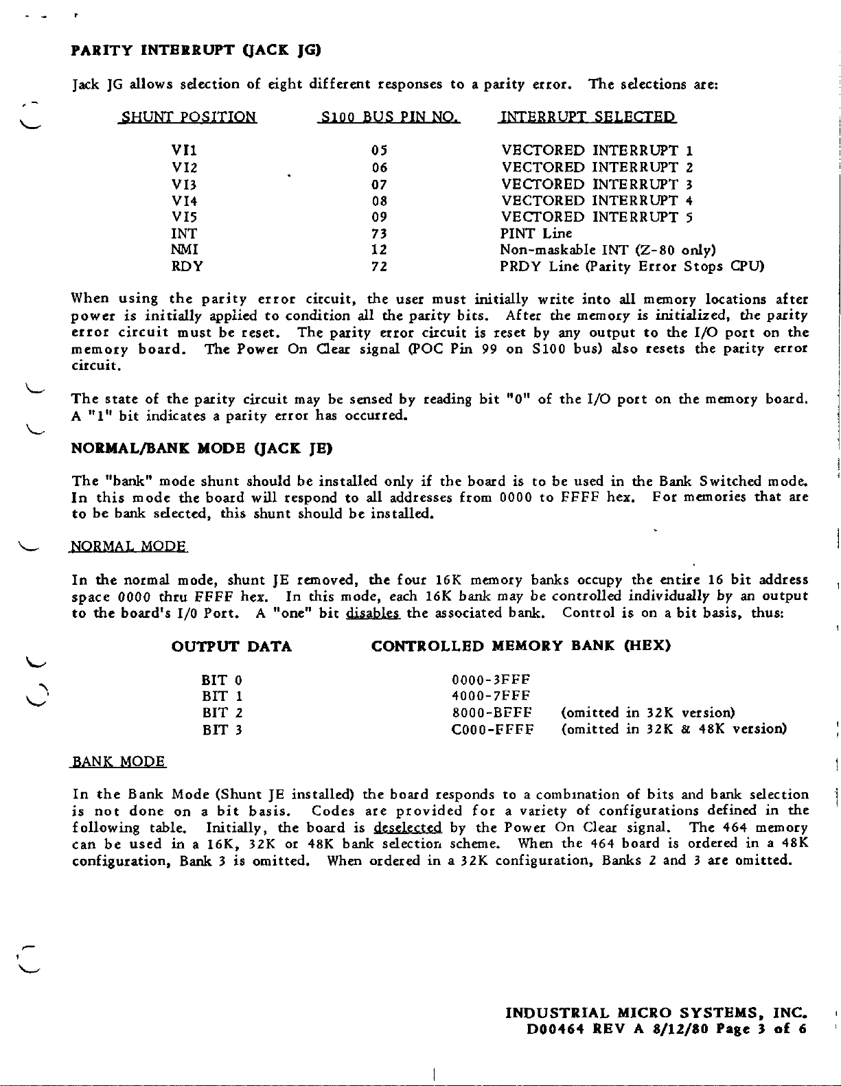
BANK MODE TABLE
.-
OUTPUT
o
1
2
3
4
5
6
7
8
9
A
B
C
D
B
F
DATA
All
Banks
Banks
Banks
Banks 0 & 1
Banks
Bank
Bank0Occupies
Bank
Bank
Bank
Bank 3 Occupies
Bank
Bank 3 Occupies
Bank
Bank 3
STANDARD CONFIGURATION
IMS
supplies
the
464
board
configured
MEMORY MAPPING
Banks
Deselected
0 & 1
2 & 3
0,
2 & 3 Occupy
0 Occupies Addresses
1 Occupies Addresses
1 Occupies
2 Occupies Addresses
2 Occupies
3 Occupies
Occupy
Occupy
1, & 2 Occupy
Occupy
Addresses
Addresses
Addresses
Addresses
Addresses
Addresses
Occupies
as
follows:
Addresses
Addresses
Addresses
Addresses
Addresses
Addresses
8000-FFFF
8000-FFFF
OOOO-BFFF (48K)
0000-7FFF
0000-7FFF
COOO-FFFF (16K)
0000-3FFF
0000-3FFF
COOO-FFFF (16K)
0000-3FFF
0000-3FFF
COOO-FFFF (16K)
4000-7FFF
8000-BFFF
COOO-FFFF
(32K)
(32K)
(32K)
(32K)
(l6K)
(l6K)
(l6K)
(l6K)
(l6K)
(l6K)
(l6K)
J
Four
serve
Note:
JACK
JA
JB
JC
JD
JB
JF
JG
JH
spare
as a
464
DESCRIPTION
Memory
En
I/O
Phantom
Normal/Bank Mode
CPU
Parity
Front
shunts
convenient
boards
Speed
I/O
Selection
Selection
Interrupt
Panel
are
installed
place
shipped
Line
to
in
on
store
systems
the
spare
STANDARD
H
Open
All
Shunted(Etch)
Open
Open
All
Left
upper
will
pins
shunts.
normally
Position
Positions
Open
Position
of
be
CONFIGURATION
Shunted
Shunted
Shunted
Jack
G.
These
configured
to
pins
are
all
connected
the
system requirements.
by
etch
.,
and
INDUSTRIAL
000464
REV A
MICRO
8/12/80
SYSTEMS
Page4of
INC.
6

AD
(13-00)
AI5
AI4
RFSH
DO
ADDR
MXPR
14J
8
,
DATA
OUT
BUFFER
'7
BANK
SELECT
LOGIC
RAS3
RAS2
RASI
RASa
PARITY
GEN
8
D
I--
I--
I----
'--
DIN
OUT
A
R
A
R
A
R
A
R
04K
MEMORY
X 9
ARRAY
BANK
RAS3
RAS2
RASl
RAsa
v
Dr
PHANT
D
A
07-
SO
P
ME
PSY
P
S0
D
PW
OM
BIN
D
00
UT
WR
MR
M1
01
02
NC
WR
UT
07
AIT
8
8
,
DATA
IN
'-
CHECKER
"8
PARITY
BUFFER
I
JD
\.8
\.
~
SELECT
r.IK
Pia
LOGIC
0S,Jc)
}'4
BANK
LATCH
P,
E.
BOARD
F/F
SELECT
4
LOGIC
-
(J
E)
~E.
1-
~
\J
0-
VI1
0-
VI2
0-
VI3
0-
VI4
0-
VI5
0-
INT
0-
NMI
0-
RDY
JG
MEMORY
START
AND
TIMING
LOGIC
(IN)
(JA)
(JF)
BLOCK
INDUSTRIAL
D00464
REV
DIAGR
MICRO
A
SYSTEM
8/12/80
AM
S.
Pale
5
INC.
of
6

I
lOP
to7
10.
lOt
10.
In
102
ID1
1009
10
"
E::::J-
'O~:,u
l.,-.,.....JU~
o~
;Ir~
CU~
C" P
~
IHDUITIIAL
c S
Q C
Q
en.
...
..,
COO""
MAD.
,,"~~
~~'~
~ ~ ~
-~
~
_~
7'~
~
.,=,
_~
UUUUUU0
-
=>-
-=- -=>- -=- -=-
~D
O~
-=-
!13
000000000
MICIO
IN
U.I.A
00000000
-=>-
I 2 2 4 S 6 7 • 9
~
.,nIMS
,
-0-
JG
a
:_~Zi~
> » _ •
- =>- -=- -
9
f
31
_1
I
0LIt
-=-
::>-
~
,.
JH
'0
:'"
l<l
):
t%lt""
<s::
>(:;
col<l
';:::0
N
CIl
";;000<
ClCll
"'..,
..
ttl
"3:
n
CIl
",.
o ...
... 2:
",["I
SEE
PG.3
SEE
SEE
PG.2
PG.
2 I
STRAPPING
(.'
(
( ( l
~ ~
~
_=-
-=-
I
-ld
-=-
-::l-
~f
n
7.
7',.-.
_::>-
-=-
2J
'--SEE
SEE
MODEL
OPTION
u
__
C35
W
~~
I I
PG.
2
464
0
o0
I.
I/O
Jt
"
'~
~j
SEE
PG
PG
2
LOCATIONS
~/
r--l
"
SEE
2
0,:
~
'~'O
JUMKI
I.
'0
PG.2
0
JfO
"
14
0'90;9
-e=J-
I'
I
19
00
lOla
~
c:
o
~iO-GJ
o
IS
o
ON
CO,nIGM'
(
16
19ft
•
~
•

5'1'UT
PWll-
MW~IT,
PSYNC
e07+
5M£
,.,...
_offtII_IIO'_.~
...
45
,+@
~
- <.1£t
~I-t'
25
A+
PHL
SM
¢
PH¢
Pp¢>
-Pip
WA
U-
II<+@-
I+~~S
~+
24
LV-
74
-
C-
[1+
27
77
1~3
....,........
140
I 2 7
1:
~
I:
-;-
,:-p
~o
4
2~
~
8
6 24~
1I~9
16
.J±!2.
'"
V
(\
--
~I,A
9
.!$&
2u~Qk
74
3
",I,.;
VCt
'
4-
,-----p-;t-
z
Q7~
c
"il
CL
I
4-
20I.6
1 /
~/56
..
~J
Ii
G
~
~
2.
~74
G Q
~
~2
".
,S
21G
..
A
156
5
15D
=
Q'
74
13
41&£
prz
CL
I
+5
5
1+
'>
rll4
/23
CL
T'
+5"
:fH
0
9
~)O I
~
~
8
-i
I
140
f?:
,.
~
140
I 5
9~
S
0"-
'0
I
~
1'--:--
V
NI<.
liD
=
13
00"\.1I
3
12
B
140
J"F
8080
~~
liD
2
00
I
"'"
+S
v
"
4,7K
11
r
04
~
"
4 = I •
S;~'--
_.-132
~
16e
"
10
14
6
+5
+S
--
~
TJ50+
CSo
IOooP':
C
bJ
~
!6D
MeEAO-
JO~
~
9 0
~
WE-
00)8
~
II
"(
\
(
14.
--
"
I
10
~-----------<
1<CL-
13·
14-
I
IN
iTL
"
1;50
"
DElAY
tloO
"t150 "t2CO t2S,
4 10
H
vee
LilJt:.
7
"I
13A
B
JA
L
-=-
...
12A
S
(
BS
0UT+
W£+
pw£+
I
.~
"'''NE-
1<+
MEM
T50
...
TIOC
T+
STA
D
_.
12
"
P,7
~
RFSH-
+s
~
'0
p~
"12-
4
'3
~~
I'
PO
II
CL
+s
Z
3
9
/5C
74
GiS
"
1413
02
~
----2. Q G
1
4
/S'c
---....J?~
2
"I
5
J74
CL
I'
+5
INDUSTRIAL
.~
..
u:
_~
10-28-80
64K
L00464A
I\JO\..I
E ,
DYNAMIC
I
........
III
~
MICRO
av,
i
--
RAM
IcAS
ICA'S'
SY:
+
STEMS
ORAwN.V
g Q
W'
f
I
"j"wa"FU"S-

T50+
ICAS-
A\5+
,.c
Jl-l+
A1>+<@
A
12+
All+<@
Al0
A9+
AB+@
P"~NTOM-
D01+~
DIl>0+
01215+
DI2I4+~
D12I3+
D02~
D0H-
00
PWR+
ADDR+
PP.0C-~
~lEMR+
POBIN+
T50+
5TART+
----
--
32
B~
33
31
3~
'01
40
8~
35
3b
18
\3_
1~1
DO'
00
00
~
J
!l!8
J
IDA
II
3
<D
8
15
A1
JE
~BANK
3 0,,373
1Li
13
4
18
17
1
8 D
,!!
D,
D;
D.
D
D"
D,
LE
2
Do
15 I
O.
lZ
a,
5
Q,
1~
Q
1
1
,
OlE
Q.
G,
a,
1<0
<0
~
~
G It244r.l'1..
4 L
8
:J
15
11
\~
11
2 lr--
Is
1,
~;
1...5
I
1~
+5
\1
W 8
9
~BD1+
(ii,
~BOIO+
0,
~BD5+
~BD'H
0.
0,
1
(iI.
1
~7
~Q
1'21
~
~
IO
~
3
1'1.0
I
61'113+
6~11.+
BA11+
BA\O+
BPl.9+
BA8+
WO
BO,.
5
D,ns
BD'2+
12
~
~
.---=
D,
Do
OK
BD1+-
BDO+13 D30315
+5
~1Kt
\0
+5
I3B
~.lK
e>
JO
(PH)
7
(
Q
10
Q,
2
Go
CL
130
1
1
Z
3
4
'7
(;,
~
,12
~
,~
\5
1 Ab
2
3
~
1 Fl2
<;;
5
,12
~
,,=-"
04'"
~~
AS
121
I2lZ
01
01
10
\1
Il
Il
M
A,
AZ
I'll
1'10
CEO
CE1
%1-01
A1
~5
~4
A3
AI
flO
CEQ
eel
'l<01-OZ 13C
IcC
Z
1100
5
4l
10_
:3l
'---~
q
5
10
'I
<0
f
3
l~A
10~15D
l.O!Q
16
Zm
1
-
~,,,
32
13
1110-=
3<'
'/
..
__
..
-
''0
=
e 4 = »L
1
~
00
~
(
::...l
( (
--"
INDUST RIAL
.c~u
"J
DIU
E - I
....
c
...
n
IO~::z.8'80
64K
, RE'O'UC
DYI\IAMIC
L00464
""0'0'."
A
MICRO
~'
RAM
-,
RAS3-
RASl-
R~SI-
RASo-
BDSEL+
D~EN-
10WT-
PPPC--
OBIN +
SYSTEMS
I
DRAwt<_y
I
I
iAWOFuM·S
RJV

.
A7+
A(,,+
AS+
AY+
A3+
A2+
AI+
AO+
r-
~'6
>-----05
>---<:,~
..--
f---o2
~)1
f----G
POR,
C?
BSQlUT+
SlNP+~
JC
l'
D
3'
c
IB
h
1G
Is
l~
3
1
j 2
11
SELE[,
12
1\
J.ll'
+5
~.1K
+5
+S
+5
+5
+5
+5
+S
145
13
o~
11
IS
13
II
a A3
c;;
4
'L
18
1~
I~
12
~
1
5
3
A1
AGo
I\S
A7A1
51;,
55
54
53
52
Bo
AY
AO
2SLS2S11
B7
~=B
51
E
1
c-r
19
lUI
EN
J5
IIIJJ
4.1K
+S
13
l,l2!\
~
(
(
-c'
(
•
j
,
~
4
\4
AllOR +
.
,-
-_
INDUSTRIAL MICRO
.c~~.
l-Jot.JE.
C.VR
IO.Jt8-60
64K
L00464
..
jj''I;o.;'
DYNAMIC
A
RAM
SYSTEMS
DR.WN
RV
RJV
I
..
IYI.le
•
ID
AW
FUMS
O
3

MC32'i2
81>-13+
/>.10+
82
81>-12-+
AS+
2~
BA11+
A'J+
30
BA10+
M+
31
BA':l+ 9 AD
81
A2+
BAB+ 8 A':l
A1+
80
Al+
83
AD+
19
ICAS+ 1
T100+ 3 RoW EN =
ICA5-
R~SO-
20
10
21
<0
25
21
2'1
2&
23
Z
1
A7.-
AIO
AI
A"
Z
All
Al
AS
Arl.
A13
COUNT
RFSH
A8
/>.3
M
EN
~~
19
05
''''
(iJq
17 "
1213
118
1iJ2
:1.
~13
'
00
11
28
y,,~
6ND[:4
~
+5
+12.
8[
V'DD
AI.
As
1Z
II'!
lOA>
131\241'"
5
P.\
11
AD
~~
\Jss
+5
ZI
131
12
10 04 'I I 0 z
3
lZA
'IT
=
TyPT.Cp,.\.
UA
A.LL
+S
~[
V,
"
pPD
Vee
-S
CONNECTION
"RAMS
IIA
McA5-
BIlP+-
BD7+
_2.
BDG+
_2
BIlS"-
__
\)04+----..&
I>D3+
_2
BD2+
BD1+
BOO+__2
_2
_Z
(;,'jK )(
Z
10
20
3D
2
'"ID
5D
GD
10
BD
9D
15TT15'r\
'"I
UPO'"l'"
:l
zc
3C
'1C
5C
<;,c
lC
Be
I
3C
MEMOR~
IC
16
26
38
'"18
5B
<;,8
1B
8B
'JB
ARRAY
15
'31>-
q
\A
H.
3A
41>-
5~
<;,~
111
51>-
15i
1\'"1
1
M01+ 310);"'37
'4
I''!
MDG>+
14
1
MD5+
'
1
'1
MOO+
1
'l
50
'"1101
71D2
~I~:
QI~
01.1
r.;
~DI0+
(LQj
19
1E
MDP+
~
r'll.>
Dll+
01"+
D15+
1'.1151-
RAS2RAS3-
~~
,- _
...
-_
..
lb'
._:;------
I
I
I I
(~
. (
l
.....f...,.
I
L00464A
I
c/>.s-
'"
R-lV
RAM
(_J~toF··5
Ie
~1KLK~
B01+
BD~
BD5+
B04+
8D3+
BD2+
BD
,.,.
BDO+
p!Zc+
IOWT-
MEMf\!-
!>DSE
\:l-
CAS-
ADDR+
DBIN+
tlt.;V
+8V
+8V
GNO~
GoND~
t5
L
<1J
----------((
I8
2
Il
1 Ie;,
11
IS
91'1
8
lZ
10
4
E9l
13
IZ
II
10
LSO
I
"!:LC%
I
11~3
'5VF
Z5V
+1.C12
15UF
Z5V
IN
3E
(D
VRZ
0 ,
+1-C31
l.
I
'~+5
'.J
+1
I
!
'5UF
Z5V
I
CI~_
1.1
I50V
+12
¥~:
CI,
'12,
42,4Q,%
CIO,
Q9,
;-(
MDP+ ----.!J
MOl
+
----.1.
----11
MOb+
11
D5
+
----1Q
MO'1
+
------1
M03+~
MOZ+
__
8
MOl
+
----.-J.?,
MDO
oj-
-----'!.
\~B
to
\~
+5
lGA
4
5138
I
'-
3,5,1,'),
n,
11,
1~,
18,
1~,
31,
33,3S,qo,
1'l,ZQ,Z5,Zb,~8,
10
lO,
'
-lID
18
Il
It.;
IS
1'1
13
12
11
10
lZ
15
lao
,jJJl
'-11K
~!
(
EE
I
----/"
St
=
5
~
1
14
53,5~,55,51D)51
l'"
(
BDP+
+5
~
(
~
0--0
>-<l
0--0
>-<l
>-<l
--Q
~1)
PARITY
Rl
330
JGo
0------3>
~
o----{D
o--[]>
o----ID
o----@
o---{]I>
<>---{It>
CRI
14B
IO~=
5)
0;
101
\1
DZ."-
l.'iA
10 \ 8
-
~
lSI',
10
Il~pr
o
Q-=--
"c
Q
9
B
1(,A
1 -
35
f
21
)3
IZ
lioA
~Il
~
,:,
~
Z
M
'3
10
1
VR3
-I
rr-r-----r--
I
5
.1
C2,"I,(,,8, \5,11, 1'),Z1,
SOV
23,28,30, 32,
~
'13,
'is,'n
35
;-
3~,
3'),
8
RROR
E
VII-
V12-
'V13-
010
VI~
VIS-
PIN1NMI-
PRDY
+
+
)
L"".....,......."",_
...._..."".
....,.
INDUSTRIAL
.c
....
"'.IOfl"..1E
DAU
IO-zs.eO
64K
I
APPRO""".?
II
DYNAMIC
L00464A
MICRO
RAM
SYSTEMS
I
DRAWN'"
"I,
-J
__
...
~
:0
OF 5
'I
 Loading...