

A
IB-30B002
LUMINARY SERIES MOTION CONTROLLER FEBRUARY 2014
LUMINARY CONTROLLER
LMC-400
INSTRUCTION BOOK
INDUSTRIAL INDEXING SYSTEMS, Inc.
Revision - 0
pproved By:
Proprietary information of Industrial Indexing Systems, Inc. furnished for customer use only.
No other uses are authorized without the prior written permission of
Industrial Indexing Systems, Inc.

INDUSTRIAL INDEXING SYSTEMS, Inc. IB-30B002
LUMINARY SERIES MOTION CONTROLLER USER’S GUIDE
TABLE OF CONTENTS
List of Illustration................................................................................................................................................... v
Introduction..........................................................................................................................................................vi
SECTION 1 - OVERVIEW
1.1 Identifying the Luminary Controller......................................................................................1 - 1
1.2 Luminary Controller Mounting Plates……….………………………………………………. 1 - 2
SECTION 2 - DESCRIPTION
2.1 Components.........................................................................................................................2 - 2
2.1.1 Status Indicators.....................................................................................................2 - 2
2.1.2 Connectors .............................................................................................................2 - 2
SECTION 3 – LUMINARY CONTROLLER SPECIFICATIONS
3.1 General.................................................................................................................................3 - 1
3.2 Power Requirement.............................................................................................................3 - 1
3.3 SBI Interface.........................................................................................................................3 - 1
3.4 Environment.........................................................................................................................3 - 1
3.5 Communication Ports...........................................................................................................3 - 2
3.6 I/O Interface..........................................................................................................................3 - 2
3.7 Encoder Interface......................................................................................................... ........3 - 2
SECTION 4 – LUMINARY WIRING
4.1 J6 Executive Port.................................................................................................................4 - 3
4.2 J7 Applications Port .............................................................................................................4 - 3
4.3 J1 & J2 Digital Inputs ...........................................................................................................4 - 4
4.4 J3 Digital Outputs.................................................................................................................4 - 5
4.5 J4 Power Input.....................................................................................................................4 - 6
4.6 J5 & J9 Factory Configuration Ports....................................................................................4 - 6
4.7 JP1 Jumper Selection..........................................................................................................4 - 6
FEBRUARY 2014 TABL E OF CONT E N T S iii

IB-30B002 INDUSTRIAL INDEXING SYSTEMS, Inc.
USER’S GUIDE LUMINARY SERIES MOTION CONTROLLER
SECTION 5 - STATUS & ERROR CODES
5.1 Controller Status ..................................................................................................................5 - 1
5.2 Device Port Status Display ..................................................................................................5 - 3
SECTION 6 - INSTALLATION GUIDELINES
6.1 General.................................................................................................................................6 - 1
6.2 Enclosure Cabinet Requirements........................................................................................6 - 1
6.3 Mounting the System Unit....................................................................................................6 - 1
6.4 Cable Isolation Requirements .............................................................................................6 - 1
6.5 Grounding Requirements.....................................................................................................6 - 1
6.6 Installation Drawings............................................................................................................6 - 2
SECTION 7 - CABLES AND ACCESSORIES
TABLE OF CONTENTS iv FEBRUARY 2014

INDUSTRIAL INDEXING SYSTEMS, Inc. IB-30B002
LUMINARY SERIES MOTION CONTROLLER USER’S GUIDE
LIST OF ILLUSTRATIONS
SECTION 1 - OVERVIEW
SECTION 2 - DESCRIPTION
Figure 2.1 LMC-400 Layout.....................................................................................................2 - 1
SECTION 3 – LUMINARY CONTROLLER SPECIFICATIONS
SECTION 4 - LUNIMARY WIRING
Figure 4.1 Luminary Controller Wiring.....................................................................................4 - 2
Figure 4.2 Input Wiring.............................................................................................................4 - 4
Figure 4.3 Output Wiring..........................................................................................................4 - 5
SECTION 5 - STATUS & ERROR CODES
Figure 5.1 SBI Status Displays................................................................................................5 - 3
SECTION 6 - INSTALLATION GUIDELINES
SECTION 7 - CABLES AND ACCESSORIES
FEBRUARY 2014 LIST OF ILLUSTRATIONS v

IB-30B002 INDUSTRIAL INDEXING SYSTEMS, Inc.
USER’S GUIDE LUMINARY SERIES MOTION CONTROLLER
INTRODUCTION
Thank you for selecting Industrial Indexing Systems LUMINARY Series products. You join many other
companies around the world in your choice of these powerful, flexible motion control products.
The LMC-400 embodies a blend of open architecture features with a true real-time operating system. The
result is a state-of-the art performance and superior connectivity to other systems and network components.
The LMC-400 has a wide array of hardware features, including
a 32-bit ARM processor,
a Executive serial port (USB-B),
an Application serial port (rs232),
Eight configurable general purpose isolated digital input’s (Can be configured for up to Two Encoder
master follower input’s with Position Trap input),
four general purpose isolated digital outputs,
Configurable programmable limit switch (PLS) functions,
two software simulated motors (master pacers),
high visibility status displays.
The LMC-400 has a wide array of software features, including:
The controller is programmed using our friendly Emerald Motion Programming Language (EML)
and powerful new Emerald Development Environment (EDE) software tools for the PC.
A Dynamic Link Library (DLL) is available to communicate with the LMC-400 using your own Visual
Basic, Visual C++, or other programming language allowing for full system integration, automation,
and data logging solutions.
A Human Machine Interface (HMI) touch screen can easily be added to the LMC-400 system using
either the USB port or the rs232 port.
The External computer and or HMI will have unlimited access to the system memory area with the
ability to control the LMC-400 remotely.
Contact IIS for full system solutions utilizing computer programming or HMI systems.
INTRODUCTION vi MARCH 2011

INDUSTRIAL INDEXING SYSTEMS, Inc. IB-30B002
(21)
LUMINARY SERIES MOTION CONTROLLER USER’S GUIDE
SECTION 1 - OVERVIEW
This manual is organized so that information is easy to find and easy to use. It begins by detailing how to
identify the LMC-400 Controller. This section is followed by a general description of the product and its
components. Next, a comprehensive hardware specification is provided followed by connector wiring
diagrams. The section that follows documents the controller status displays. Sections on LMC-400
installation guidelines and cables drawings round out the manual.
1.1 IDENTIFYING THE LUMINARY CONTROLLER
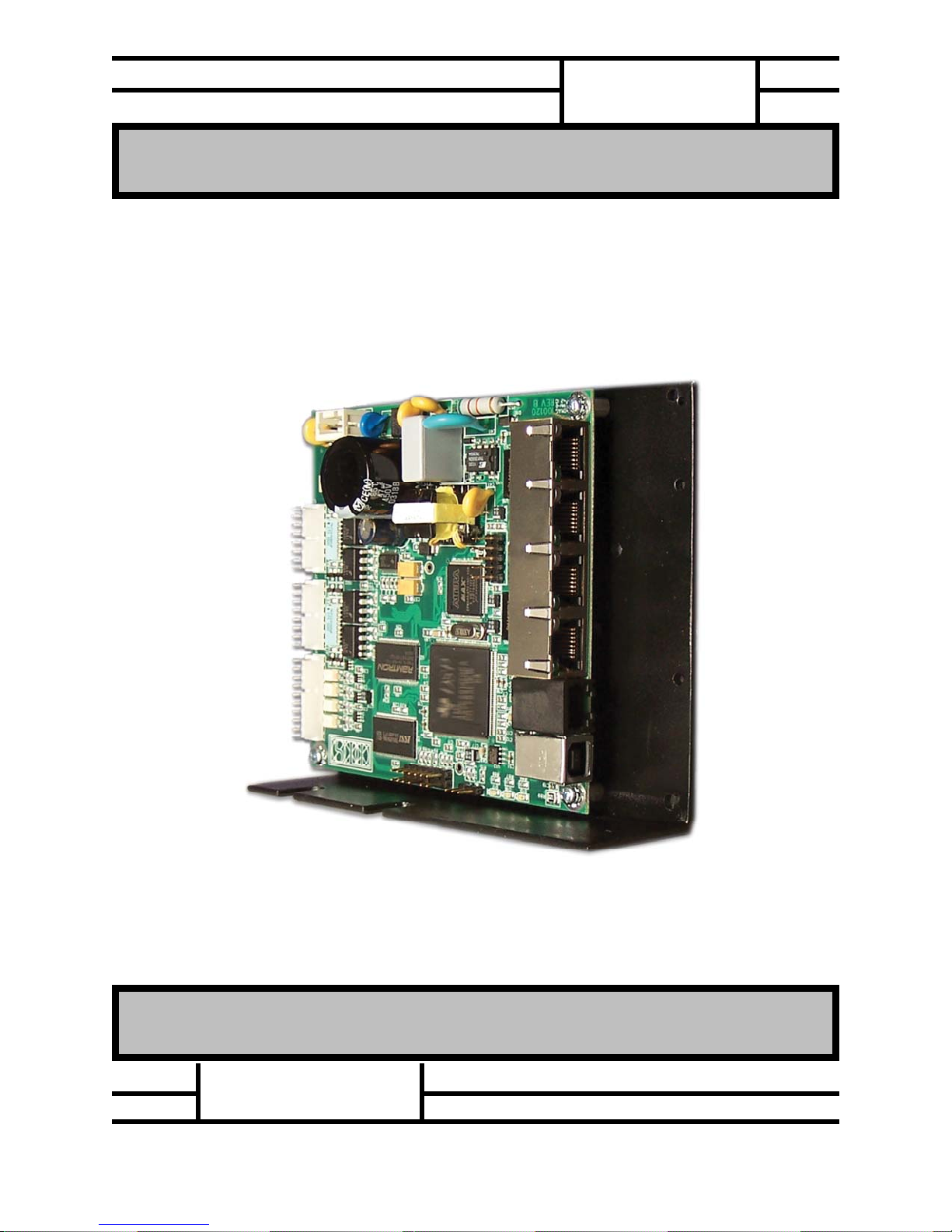
Luminary Controller packages can be identified as follows.
Your LUMINARY Controller model number uses the following designations:
The LMC-400-00 is the basic controller without a base plate or mounting options
Part number identification
LMC400XX
Example part numbers:
LMC-400-00 Luminary Controller without mounting base plate option
LMC-400-21 Luminary Controller with L bracket mounting plate
Mounting Option
(00) = No Mounting Plate
(01) = Flat Plate
= L Bracket
Special Options
(00) None
Number of Master Ports
(4)
Controller Series
(LMC)
FEBRUARY 2014 PAGE 1 - 1
IB-30B002 INDUSTRIAL INDEXING SYSTEMS, Inc.
USER’S GUIDE LUMINARY SERIES MOTION CONTROLLER
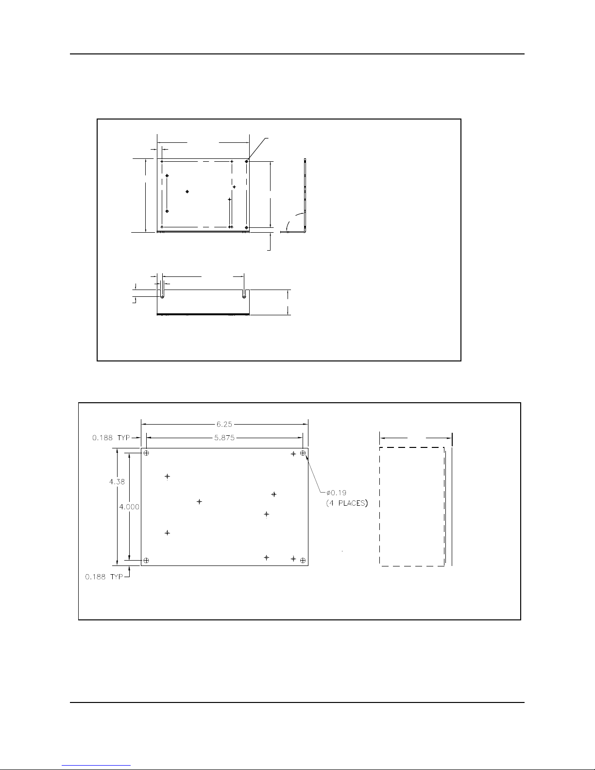
1.2 LUMINARY CONTROLLER MOUNTING PLATES
The Luminary Controller mounting plate drawings are shown below. Other options may be available.
0.29 [7.5]
5.50 [139.7]
4.38 [111.1]
0.19 [4.8]
4.88 [124.0]0.31 [7.9]
0.39 [10.0]
For a compact single axis positioner, one Luminary Drive (LD-330) can be the
mounted on the opposing side of the “L” bracket.
0.13 [ 3.2 ] (5 PL ACES)
3.91 [99.3]
90°
0.30 [7.5]
1.50 [38.1]
Flat plate mounting
Minimum Height C learance
2.50
PAGE 1 - 2 FEBRUARY 2014
INDUSTRIAL INDEXING SYSTEMS, Inc. IB-30B002
r
LUMINARY SERIES MOTION CONTROLLER USER’S GUIDE
SECTION 2 - DESCRIPTION
The Luminary LMC-400 product is a SBI Master servo motion controller, with the ability to command up to
Four Slave Luminary Devices. The application program that operates the controller is created on a PC
using the EDE software tools and sent serially to the controller via the USB or RS-232 link.
All commands used by the LUMINARY are part of the Emerald Motion
Language (EML). Refer to the Emerald Development Environment
(EDE) PC tools online help for detailed information on the commands
and their proper usage.
2.1 COMPONENTS
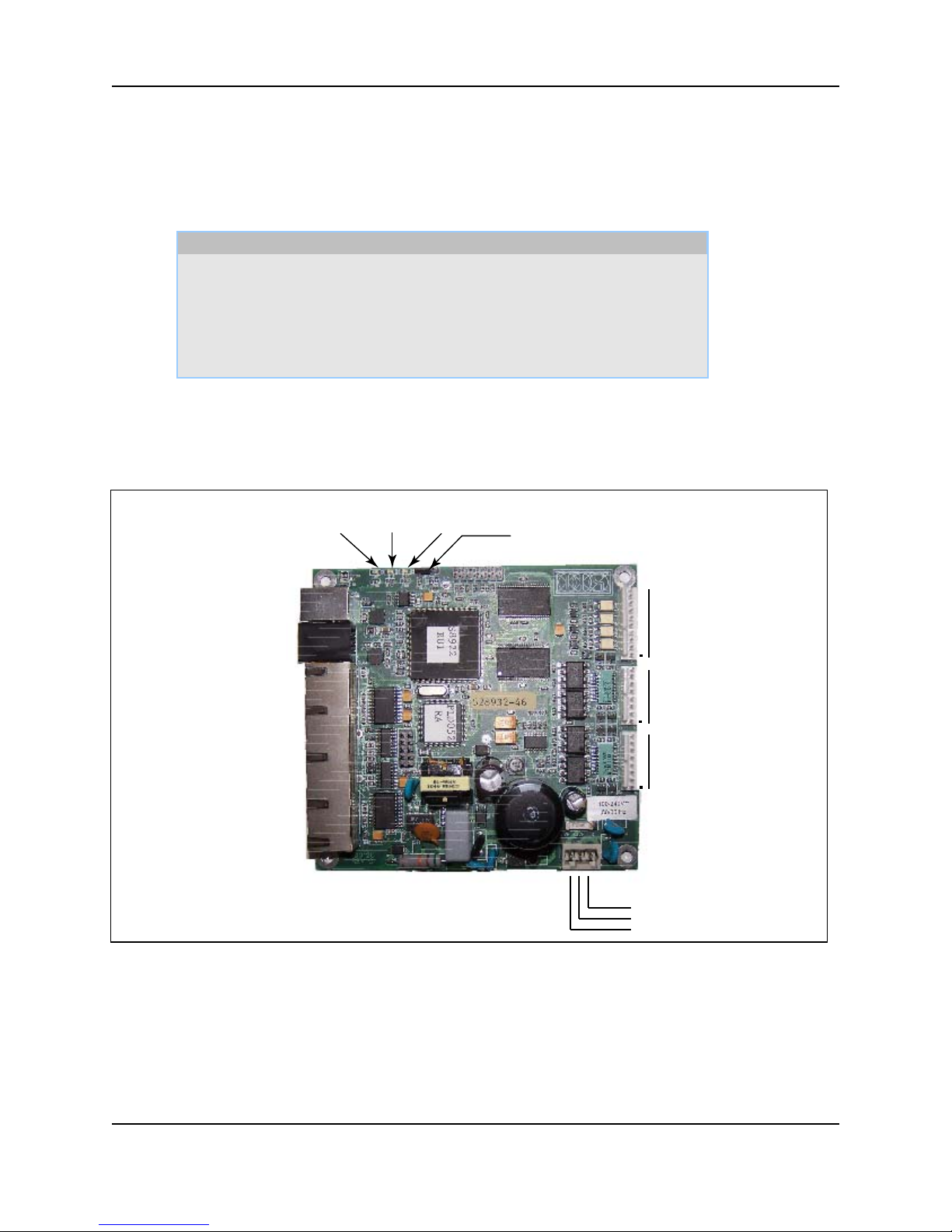
The external connections that exist on the Luminary are shown in Figure 2.1, and consist of USB,
RS-232 ports, General purpose Input’s and Output’s, Four SBI Ports, and a power connection.
Controller Status Indicators
Red Green Yellow
NOTE
Jumper JP1 must be installed between
pins 1 and 2 for controller to boot.
Executive Port (USB serial)
App Port (rs232 serial)
SBI Port 1
SBI Port 2
SBI Port 3
SBI Port 4
Device Network Hub
J6
J7
J8-1
J8-1
J8-2
J8-2
J8-3
J8-3
J8-4
J8-4
J4
Outputs 1 - 4
J3
Inputs 5 - 9 / Encoder B
J2
Inputs 1 - 4 / Encoder A
Power Input
Connecto
Figure 2.1 – LMC-400 Layout
FEBRUARY 2014 PAGE 2 - 1
IB-30B002 INDUSTRIAL INDEXING SYSTEMS, Inc.
USER’S GUIDE LUMINARY SERIES MOTION CONTROLLER
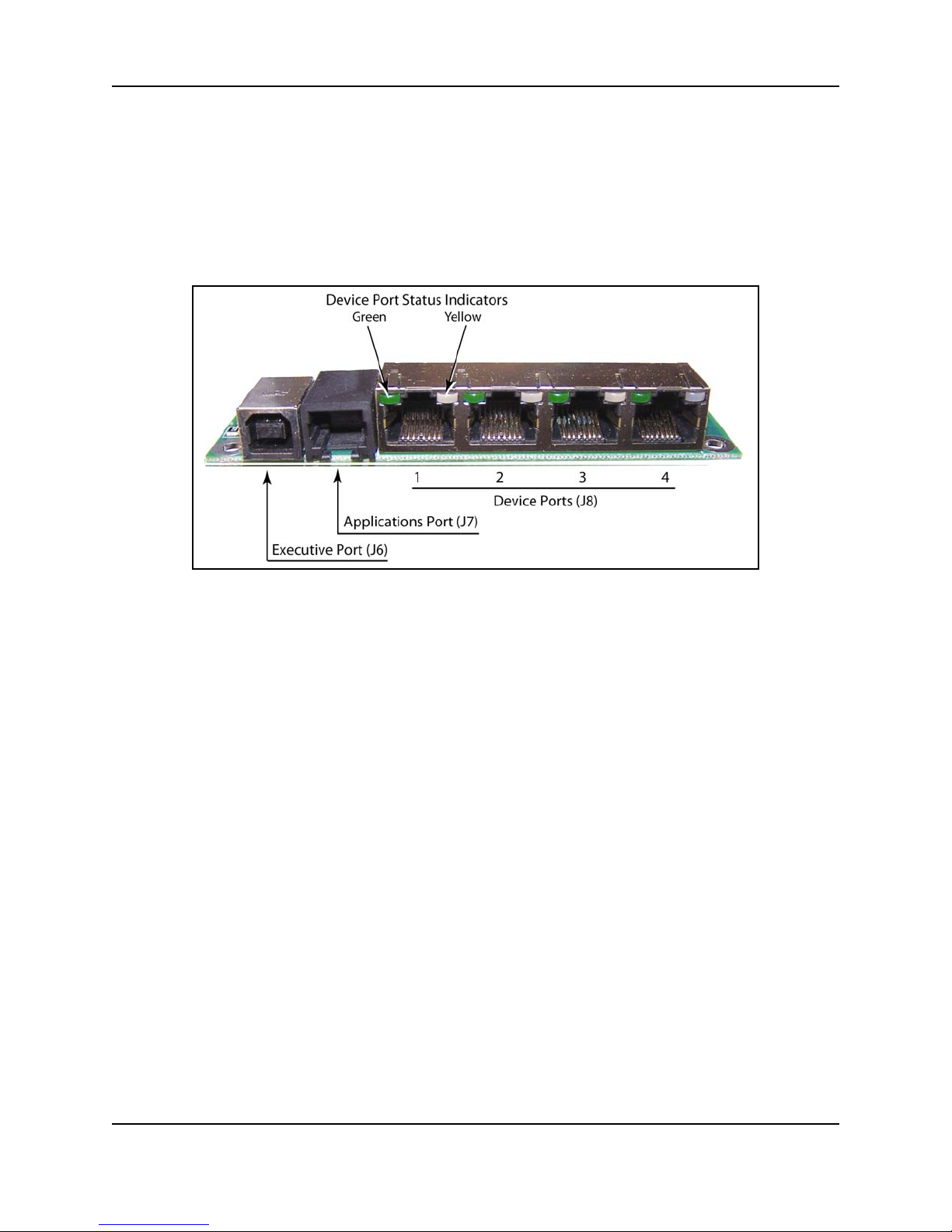
2.1.1 STATUS INDICATORS
Controller Status Display – These three LED’s define the current status of the controller. See section 5
and figure 2.1.For indicator status information, refer to Section 5 - Status & Error Codes
SBI Status LEDs - These 2 LED’s indicate the status of the SBI Interface. See Section 5 and
figure 2.1
.
2.1.2 CONNECTORS
Executive Port - This 4-pin USB-B connector is an USB 2.0 serial communication port. The
protocol is the EML custom protocol for communicating with the EDE software tools on a PC.
Application Port - This 6-pin RJ-11 connector is an RS-232 serial communication port. It can
be used to communicate with a Maple Systems Touch Screen OPI-7.0TFT or other size available
from IIS or similar RS-232 type devices. The protocol is selectable through the EML
programming language. This port defaults to the custom protocol for communicating with the
EDE software tools on a PC unless configured otherwise in the EDE program.
Device Network Hub - This Quad 8-pin header is the interface hub to the slave SBI devices.
The SBI devices are setup in the EDE project configuration.
Digital Inputs - These 8-pin headers are high-speed inputs that can be configured in the EML
programming language to be generic input’s, or master encoder pulse input’s with Trap. See
section 3.6 and 4.3.
Digital Outputs - This 10-pin connector provides four generic outputs that can be configured in
the EML programming language. See section 3.6 and section 4.4.
Power Input - This 3-pin connector is for powering the Luminary Controller. See section 3.2 and
section 4.5.
PAGE 2 - 2 FEBRUARY 2014

INDUSTRIAL INDEXING SYSTEMS, Inc. IB-30B002
LUMINARY SERIES MOTION CONTROLLER USER’S GUIDE
SECTION 3 – LUMINARY CONTROLLER SPECIFICATIONS
3.1 GENERAL
Weight
LMC-400-00
LMC-400-01
LMC-400-21
0.25 lbs / 0.11 Kg
??? lbs / ??? Kg
??? lbs / ??? Kg
Dimensions
W x H x D
Minimum Enclosure
Depth
Minimum Enclosure
Depth
LMC-400-00
LMC-400-01
LMC-400-21
LMC-400-01
LMC-400-21
4.20 in (106.7 mm) x 1.10 in (28.0 mm) x 4.50 in (114.3 mm)
4.20 in (106.7 mm) x 1.10 in (28.0 mm) x 4.50 in (114.3 mm)
4.20 in (106.7 mm) x 4.50 in (114.3 mm) x 1.10 in (28.0 mm)
At Least 3.00 in (76.2 mm) Mounted On Flat Plate
(See Section 6 - Installation Guidelines)
At Least 6.00 in (152.4 mm) Mounted On L Bracket
(See Section 6 - Installation Guidelines)
3.2 POWER REQUIREMENT
Supply Voltage 100V to 240V volts AC +
10%
Supply Current 0.5 amp max. Internally Fused
Inrush Current 30A @ 1ms
3.3 SBI INTERFACE
Network Topology IIS Serial Bus Interface (SBI)
Transmission Rates 4.0 MB/second
3.4 ENVIRONMENT
Storage
Temperature
Operating
Temperature
-10 to 70C / 14-158F
0 to 45C / 32-113F
Humidity 35 to 90% Relative Humidity, non-condensing
Shock and Vibration 1 G or less
Operating
Conditions
FEBRUARY 2014 PAGE 3 - 1
Free of conductive dust, liquids, metallic particles and corrosive gases.
Use in a pollution degree 2 environment.

IB-30B002 INDUSTRIAL INDEXING SYSTEMS, Inc.
USER’S GUIDE LUMINARY SERIES MOTION CONTROLLER
3.5 COMMUNICATION PORTS
USB-B
J6
RS-232 (RJ-11)
J7
SBI (RJ-45)
J8-1, -2, -3, -4
Classification: Serial Communications over USB 2.0
Data Transfer: EMC Packet protocol
Physical: 115200 baud, 1 stop bit, 8 data bits, No parity
Classification: Serial Communications over RS-232
Data Transfer: EMC Packet protocol (default), User Programmable
Physical: 38,400 or 19,000 baud, 1 stop bit, 8 data bits, No parity
Classification: IIS Device Network over SPI
Data Transfer; Full duplex, hi-speed serial (4.0 megabit / sec)
Physical: Four port hub
3.6 I/O INTERFACE
ON: 24V DC 10%
DIGITAL INPUTS
Connector Block
J1 and J2
OFF: 2V or Less
Input Resistance: 2K Ohms
Input Frequency: DC to 1.5 MHz.
Reverse polarity protected
24V DC 10%
DIGITAL OUTPUTS
Connector Block
J3
Output Load: 100mA DC Maximum non-inductive
Output Saturation Voltage (ON): 1.2V Maximum
Output Leakage Current (OFF): 0.2mA Maximum
Output Frequency: DC to 500Hz
3.7 ENCODER INPUT INTERFACE
(When inputs J1 or J2 are configured to accept encoder signals in the EDE project file.)
A (quadrature) B
With or without
marker
Position Capture
“Trap” input signal
Three differential Inputs A, B, Z.
Input Frequency DC to 1.5 MHz.
Input for trapping encoder’s 32 bit signed position.
Maximum Trap Rate: 1 kHz.
Trap Register is updated on falling edge of input.
PAGE 3 - 2 FEBRUARY 2014

INDUSTRIAL INDEXING SYSTEMS, Inc. IB-30B002
LUMINARY SERIES MOTION CONTROLLER USER’S GUIDE
SECTION 4 - LUMINARY WIRING
This section details the pin-outs of the external connectors on the LUMINARY controller. Refer to
Section 7 INTERFACE CABLES for part numbers of cables to interface to these connectors.
CAUTION – This device is a high voltage product operating on 100V to 240V AC and may cause injury
or death if precautions are not followed when installing or servicing the LMC-400.
PRECAUTIONS:
1) Never service the LMC-400 with power applied to the unit. There are high voltage wire ways and
components that hold dangerous voltages. Internal components on the LMC-400 can hold
voltages reaching 350V DC.
2) Wait at least 1 minute from removal of power from the system to service the LMC-400. There are
capacitors that will hold dangerous voltages on the unit for up to 1 minute after removal of power.
See Figure 4.1 below for controller interface wiring and connector pin-outs.
FEBRUARY 2014 PAGE 4 - 1

IB-30B002 INDUSTRIAL INDEXING SYSTEMS, Inc.
USER’S GUIDE LUMINARY SERIES MOTION CONTROLLER
3 OF 5
SH.
26OCT120
DATEREV
OUTPUT 4-
OUTPUT 4+
OUTPUT 3-
OUTPUT 3+
OUTPUT 2-
OUTPUT 2+
OUTPUT 1-
OUTPUT 1+
(PROBE 2-)
(PROBE 2+)
(Y ENCZ-)
(Y ENC Z+)
(Y ENCB-)
(Y ENC B+)
(Y ENCA-)
(Y ENC A+)
(PROBE 1+)
(PROBE 1-)
(X ENCA-)
(X ENC A+)
(X ENC B+)
(X ENCB-)
(X ENC Z+)
(X ENCZ-)
IC-068003
IN8+
IN8-
IN6-
IN5+
IN5-
IN6+
IN7+
IN7-
IN3-
IN4+
IN4-
IN1+
IN1-
IN2+
IN2-
IN3+
INTERCONNE CT
DRAWING NUMB ER
TITLE
CAD
SCALE:
0.4°
±
LUMINARY CONTROLLER CONNECTION DIAGRAM
NC
9
8
6745231
10
NC
5
213
486
7
6
7
8
1
243
5
LC-CO NK IT
0.005
www.iis -ser vo.com
0.020
X.XX± X. XXX±
INDUSTRIAL INDEXING SYSTEMS, Inc.
TOLERAN CES
DIMENSIONS ARE INCHES [mm]
LMC-400-XX
3
MATERI AL
FINISH
HYC/26O C T12
DRAWNBY / DATE
APPROVEDBY /DATE
L11L22NC GROUND
Figure 4.1 – LUMINARY CONTROLLER WIRING
C-894YYY
C-987YYY
OPI-433TFT
C-884000
OPI-7.0TF T
C-822000
USB
COMPUTER
RS232
COMPUTER
OPI
PAGE 4 - 2 FEBRUARY 2014
C-822000
OPI-10.4TF T
C-889000
C-822000
HMI-5100
OPTIONAL
RIGHT ANGLE
C-822000
OPI-5.6TF TE
ADAPTOR
C-866000
INPUT POWER
100-240VAC
50/60Hz
THIS DRAWING ANDTHEDATACONTAINEDTHEREIN
AXIS 1 C-885YYY
AXIS 2 C-885YYY
AXIS 3 C-885YYY
AXIS 4 C-885YYY
PROJECTION
ARE PROPRIETARY INFORMATION OF INDUSTRIAL
WHATSOEVERWITHOUTTHE PRIORWRITTEN
CONFI DEN CE AN DMAY NOT BE REPRODUCED,
COPIED OR USED FOR ANY PUR POSE
PERMISSION OF IND USTRIAL INDEXING SYSTEMS.
INDEXING SYSTEMS. IT IS ISSUED IN STRICT
12-0980HYC
PER ECN
SYM DR APP
DATE REVISION RECORD
26OCT 12

INDUSTRIAL INDEXING SYSTEMS, Inc. IB-30B002
LUMINARY SERIES MOTION CONTROLLER USER’S GUIDE
4.1 J6 Executive Port
This port is used for communication with the IIS EDE software development package and uses a
standard USB-A to USB-B cable to interface to a PC. A 15-foot cable is available from IIS; order part
number C-894015.
4.2 J7 Applications Port
This port is used for user communication and uses an RJ-11 connector to interface to rs232 devices.
Various adapters are available to convert connector on the device to the IIS cable C-987010 that
connects to the RJ-11 applications port connector. Users can connect various operator interface
terminals and communicate with them by using simple data transfers utilizing ASCII character commands
or the port can by configured to use the IIS data transfer protocol. The IIS EMC protocol is available as
selection on the Maple System touch-screen terminals.
When communicating with a PC app, IIS provides the user with a dynamic linked library (DLL) that can be
integrated into their application.
Device
Touchscreen 4.3
Touchscreen 5.6
Touchscreen 7.0
Touchscreen 10.4
Touchscreen
PC
Model
OPI-4.3TFT
OPI-5.6TFT
OPI-7.0TFT
OPI-10.4TFT
HMI-5100
With 9 pin serial port
Cable Adapter Cable
C-884000 C-987YYY
C-866000 C-987YYY
C-822000 C-987YYY
C-822000 C-987YYY
C-822000 C-987YYY
C-822000 C-987YYY
Note: the C-889000 adapter can also be used when there is the need to bring the cable out at a
right angle.
FEBRUARY 2014 PAGE 4 - 3

IB-30B002 INDUSTRIAL INDEXING SYSTEMS, Inc.
USER’S GUIDE LUMINARY SERIES MOTION CONTROLLER
4.3 J1 & J2 Digital Inputs
The Input interface connection options are shown in Figure 4.2. They may be wired for sinking or
sourcing configurations.
Input Sinking
+5 or +24 Vdc
+in
-in
Input Sourcing
+5 or +24 Vdc
+in
-in
8
7
6
5
4
3
2
1
8
7
6
5
4
3
2
1
A
l
t
e
n
r
a
t
e
i
n
p
u
c
o
n
f
I
N
8
-
(
PR
N
I
8
+
P
(
I
N
I
N
N
I
I
N
I
N
N
I
I
N
I
N
N
I
N
I
N
I
I
N
N
I
N
I
R
7
-
(
Y
7
+
(
Y
6
-
(
Y
6
+
(
Y
5
-
(
Y
5
+
(
Y
E
4
-
(
P
R
O
4
+
(
P
R
O
3
-
(
X
E
3
+
(
X
E
2
-
(
X
E
2
+
(
X
E
1
-
(
X
E
1
+
(
X
E
t
i
g
u
r
a
t
i
o
n
O
B
E
2
-
)
O
B
E
2
+
)
E
N
C
Z
-
)
E
N
C
Z
+
)
E
N
C
B
)
-
E
N
C
B
+
)
E
N
C
A
-
)
N
C
A
+
)
B
E
1
-
)
B
E
1
+
)
N
C
Z
-
)
N
C
Z
+
)
N
C
B
-
)
N
C
B
+
)
N
C
A
-
)
N
C
A
+
)
Figure 4.2 – INPUT WIRING
PAGE 4 - 4 FEBRUARY 2014

INDUSTRIAL INDEXING SYSTEMS, Inc. IB-30B002
LUMINARY SERIES MOTION CONTROLLER USER’S GUIDE
4.4 J3 Digital Outputs
The Output interface connector options are shown in Figure 4.3. They may be wired for sinking or
sourcing configurations.
Output Sinking
+out
-out
Output Sourcing
Use a reverse diode to reduce negative voltage transitions when driving inductive loads.
+out
-out
LOAD
+5 to +32 Vdc
LOAD
+5 to +32 Vdc
10
9
8
7
6
5
4
3
2
1
Figure 4.3 – OUTPUT WIRING
NC
NC
OUTP
OUTP
OUTP
OUTP
OUTP
OUTP
OUTP
OUTP
UT 4UT 4+
UT 3UT 3+
UT 2UT 2+
UT 1UT 1+
FEBRUARY 2014 PAGE 4 - 5

IB-30B002 INDUSTRIAL INDEXING SYSTEMS, Inc.
USER’S GUIDE LUMINARY SERIES MOTION CONTROLLER
4.5 J4 Power Input
The AC Power input connector.
4.6 J5 & J9 Factory Configuration Ports
Used in the manufacturing process of the LMC-400.
Do not plug any connectors into these ports.
4.7 JP1 Jumper Selection
Used in the manufacturing process of the LMC-400.
Keep jumper between pin-1 and pin-2.
PAGE 4 - 6 FEBRUARY 2014

INDUSTRIAL INDEXING SYSTEMS, Inc. IB-30B002
LUMINARY SERIES MOTION CONTROLLER USER’S GUIDE
SECTION 5 - STATUS & ERROR CODES
5.1 CONTROLLER STATUS
CONTROLLER NORMAL STATUS
LED DISPLAY STATUS SEQUENCE
CODE DESCRIPTION RED GREEN YELLOW
POWER-UP Boot in progress
System Reset / User program loaded
User Program loaded / Not running
User program running
Memory clearing in progress
SOLID SOLID SOLID
OFF OFF FLASHING
OFF FLASHING OFF
OFF SOLID OFF
SOLID OFF OFF
SEE FIGURE 5.1 FOR LOCATION OF STATUS LED’s
CONTROLLER WARNINGS
CODE DESCRIPTION
LED STATUS SEQUENCE
YELLOW
FLASHES
GREEN
FLASHES
21 Program divide by zero 2 1
22 Illegal instruction argument detected 2 2
23 Device found in wrong operating state 2 3
24 Out of bounds memory access detected 2 4
25 RESERVED 2 5
26 RESERVED 2 6
27 RESERVED 2 7
28 RESERVED 2 8
29 RESERVED 2 9
31 Communication Timeout - USB Port 3 1
32 Communication Timeout - RS-232 Port 3 2
FEBRUARY 2014 PAGE 5 - 1

IB-30B002 INDUSTRIAL INDEXING SYSTEMS, Inc.
USER’S GUIDE LUMINARY SERIES MOTION CONTROLLER
33 RESERVED 3 3
34 RESERVED 3 4
35 Illegal packet code received - USB Port 3 5
36 Illegal packet code received - RS-232 Port 3 6
37 PRINT QUEUE FULL - USB Port 3 7
38 PRINT QUEUE FULL - RS-232 Port 3 8
39 RESERVED 3 9
SEE FIGURE 5.1 FOR LOCATION OF STATUS LED’s
CONTROLLER FATAL ERRORS
CODE DESCRIPTION
LED STATUS SEQUENCE
RED
FLASHES
GREEN
FLASHES
01 Unrecognized Instruction Opcode 1 0
02 Program Load Failure 2 0
03 Write to a read-only Flag 3 0
04 Instruction Opcode Aborted 4 0
05 Configuration Load Failure 5 0
06 Stack Memory Overflow 6 0
07 Stack Memory Underflow 7 0
08 Checksum Error in Program Memory 8 0
09 Main Processor Failure 9 0
10 Communication Error on SBI Device Port 1 5 1
11 Communication Error on SBI Device Port 2 5 2
12 Communication Error on SBI Device Port 3 5 3
13 Communication Error on SBI Device Port 4 5 4
PAGE 5 - 2 FEBRUARY 2014

INDUSTRIAL INDEXING SYSTEMS, Inc. IB-30B002
LUMINARY SERIES MOTION CONTROLLER USER’S GUIDE
5.2 DEVICE PORT STATUS DISPLAY
The status LED’s of each device port on the hub show the current status of the SBI communications to
the device it is connected to.
DESCRIPTION LED STATE STATUS / SOLUTIONS
SBI communications
are ACTIVE
SBI communications
are INACTIVE
SBI receiving errors
in communications
GREEN SOLID
YELLOW OFF
GREEN OFF
YELLOW SOLID
GREEN SOLID
YELLOW FLASHING
No Problem
1) Check if program is loaded in LMC-400
2) Check if slave device is properly
configured in the EDE project.
3) Check power is on slave device.
4) Check routing of communications cable.
5) Check for proper grounding of both the
LMC-400 and the slave device.
6) Check for bad communications cable.
1) Check routing of communications cable.
2) Check for proper grounding of both the
LMC-400 and the slave device.
3) Check for bad communications cable.
FEBRUARY 2014 PAGE 5 - 3
Figure 5.1 - SBI Status Displays

INDUSTRIAL INDEXING SYSTEMS, Inc. IB-30B002
LUMINARY SERIES MOTION CONTROLLER USER’S GUIDE
SECTION 6 - INSTALLATION GUIDELINES
6.1 GENERAL
This section contains the specific information needed to properly install the Luminary LMC-400 controller
unit.
6.2 ENCLOSURE CABINET REQUIREMENTS
Ideally, the LMC-400 controller unit, along with other related electronic components, should be mounted
on a panel housed in a NEMA 12 enclosure. It is recommended that the cabinet have a depth of at least
3.00 inches (76.2 mm) or 6.00 inches (152.4 mm) depending on mounting option, to accommodate the
bend radius of the cables. The enclosure should be mounted as far away as practical from noise
generating devices, such as SCR equipment.
6.3 MOUNTING THE SYSTEM UNIT
The LMC-400 controller unit is designed for mounting on a grounded panel, and is secured to the panel
with four M3 screws. Be sure to provide adequate spacing around the controller unit for ease of
maintenance and proper ventilation. Typically wire ways are located at least 1 inch (25.4 mm) from the
edge of the controller unit back plate. When mounting the LMC-400 directly to a panel surface (not using
a back plate) a spacer of at least 0.17 inch (4.5mm) shall be used to maintain spacing between the
LMC-400 and any conductive surfaces. Refer to drawing number LMC-400 in Section 6.6 - Installation
Drawings for mounting dimensions.
6.4 CABLE ISOLATION REQUIREMENTS
It is imperative that any low-voltage signal conductors, such as resolvers, encoders or communications,
(24V or less) be routed in conduits or wire ways separate from high-voltage, such as motor cables, and
transformer lines (100V or more). This will insure that electromagnetic fields produced by high power
transmission do not corrupt the low level signals. All cabling shields must be connected according to
manufacturer specifications.
6.5 GROUNDING REQUIREMENTS
The site must have a suitable earth ground rod and ground bus installed. The NEMA 12 enclosure, wire
ways, conduits, and machine frame must be connected to this ground bus. The LMC-400 earth ground
and each slave device must be connected to this ground bus for proper operation.
FEBRUARY 2014 PAGE 6 - 1

IB-30B002 INDUSTRIAL INDEXING SYSTEMS, Inc.
USER’S GUIDE LUMINARY SERIES MOTION CONTROLLER
6.6 INSTALLATION DRAWINGS
DRAWING NUMBER DESCRIPTION
LMC-400-21 Luminary Controller
LMC-400 drawing to show drill locations, tap sizes for mounting on a panel. Also to shows aside view
describing the recommended height from back panel using recommended spacers.
PAGE 6 - 2 FEBRUARY 2014

INDUSTRIAL INDEXING SYSTEMS, Inc. IB-30B002
LUMINARY SERIES MOTION CONTROLLER USER’S GUIDE
SECTION 7 - CABLES AND ACCESSORIES
PART NUMBER
C-885YYY SBI Communications Cable
C-822YYY Cable Adaptor 9 pin female to 6 pin Modular Data Cable
C-987YYY 6 pin Modular Data Cable
C-894015 Exec Port USB Communication Cable
LC-CONKIT Connector/Pin Kit for I/O and Power interfaces
DESCRIPTION
FEBRUARY 2014 PAGE 7 - 1

IB-30B002 INDUSTRIAL INDEXING SYSTEMS, Inc.
USER’S GUIDE LUMINARY SERIES MOTION CONTROLLER
PAGE 7 - 2 FEBRUARY 2014

INDUSTRIAL INDEXING SYSTEMS, Inc. IB-30B002
LUMINARY SERIES MOTION CONTROLLER USER’S GUIDE
CKDRSYMDATE REVISION RECORD CK
EB CDR
PROPR IETARY INFOR MATION
www.iis-servo.com
PER ECN
RJ11
JACK
13MAR01 C 01-070 EB
PC-AT
DB-9F
YEL
(BLK)
2
RX
351
RED
GRN
(GRN)
(RED)
3
TX
4
WHT2BLK6BLU
(WHT)
N.C.
5
COM
INDUSTRIAL INDEXING SYSTEMS, Inc.
INDUSTRIAL INDEXING SYST EMS, Inc.
TITLE
THIS DR AWING, AND THE D ATAC ONTAINED THEREIN, ARE O F; INDUSTRIAL
INDEXING S YSTEM S, In c. AND IS ISSUED IN STR I CT C ONFIDENC E, AND IT SHALL N O T BE REP RO DUCE D,
(YEL)
(BRN)
N.C.
N.C.
2
AC
SEE NOTE 1
COPIE D, OR USED FOR A NY PURPOSE W HATSO EVER, WITHOUT THE PRIOR WRIT TEN PERMISSION O F;
DATECHECKED BY
DATE
DATE
ELS 15AUG96
APPROVED BY
APPROVED BY
REVISION
C-822000
1 OF 1
DRAWING NUMBER
SHEET NO.
NTS C
SCALE
BOWMAN
09M AY96
DATE
Q:\DFTG\CABLES\C-8XX
AutoCAD FILE LOCATION
DRAWNBY
B
-±
ANGULAR
CABLE ADAPTOR, 9P, FE, STANDARD
ELS 10MAY96
--
--
TOLERANCES
--
UNLESS OTHER WISE SPECIFIED
X.X±
X.XX±
X.XXX±
DIMENSIONS ARE INCHES (mm)
--------
--------
MATERIAL
FINISH
1
RJ11
JACK
B
SEE NOTE 2
C-822000
PC-AT
DB-9F
3.) COLORS IN (*) ARE A LTERNATE COLORS.
2.) M ARK PER Q P-08-0001.
1.) INSULATE UNUSED WIRES.
NOTES:
FEBRUARY 2014 PAGE 7 - 3

IB-30B002 INDUSTRIAL INDEXING SYSTEMS, Inc.
USER’S GUIDE LUMINARY SERIES MOTION CONTROLLER
CKDRSYMDATE REVISION RE CORD CK
CDR
EB
PROPRIETARY INF ORMATIO N
www.iis-servo.com
PER ECN
INDUSTRIAL INDEXING S YSTEMS, Inc.
1
29JAN99 A 98-270/99-027 CWB
A
SEE NOTE 2
A
INDUSTRIAL INDEXING S YSTEMS, Inc.
TITLE
THIS D RAW ING, AN D THE DATA CON TAINED THERE IN, AR E O F; INDU STR IAL
INDEXING S YSTEMS, Inc. AND IS ISSUED IN STRI CT CONFIDENC E, AND IT SHALL N OT BE REPRODUCED,
COPIED, OR USED FOR A NY PURPOSE WHATSOEVER, WITHOUT THE PRIOR WRITT EN PERMISSION O F;
DATECHECKED BY
DATE
DATE
8/31/92
8/31/92
J.C.
E. BAIER
APPROVEDBY
APPROVEDBY
REVISION
C-987 YY Y
1 OF 1
DRAWING NUMBER
SHEET NO.
--- A
SCALE
ERTURK
13AUG92
DATE
Q:\DF TG\ CA BLE S\C-9 X X
AutoCAD FILELOCATION
DRAWNBY
CABLE, DATA, MOD ULAR
MATERIAL
B
---
±
ANGULAR
---
---
TOLERANCES
---
UNLESSOT H ERWISE SPECIFIED
X.X±
X.XX±
X.XXX±
DIMENSIONS ARE INCHES (mm)
---------
---------
FINISH
2
C-987YYY
22
334455
66
A
WHT
YEL
BLK
BLU
RED
GRN
11
PIN 1 PIN 1
A
PART No. 1005-6P6C .
(ITEM 1) W ITH MODULAR CRIMP TOOL,
1) CRIMP C ABLE (ITEM 2) TO ENDS
NOTES:
2) MARK PER OP-08-0 001.
PAGE 7 - 4 FEBRUARY 2014

INDUSTRIAL INDEXING SYSTEMS, Inc. IB-30B002
LUMINARY SERIES MOTION CONTROLLER USER’S GUIDE
4
3
1
2
38
12 0 .2
USBB/M
C-894015
Red
White
Green
Black
Braid
1234G
Male
USB B
50
Pin Assignment
Male
USB A
1234G
15 Ft. Long
USB-A to USB-B Cable
FEBRUARY 2014 PAGE 7 - 5
4
1
USB A / M

IB-30B002 INDUSTRIAL INDEXING SYSTEMS, Inc.
USER’S GUIDE LUMINARY SERIES MOTION CONTROLLER
Connector - Pin Kit for I/O and Power Interfaces
As an alternative to purchasing complete cable sets, customers can assemble the system’s cables
using our standard connector kits.
Connector Kit Parts List Description Quantity
LC-CONKIT 22-01-3087 8 Terminal Connector 1
- 22-01-3107 10 Terminal Connector 1
- 734-103 3 pin Female Connector 1
- 08-55-02102 Socket Pins (note 1) 25
Note 1: Use the Molex MINI-KK Crimp Tool
PAGE 7 - 6 FEBRUARY 2014

IB-30B002
INDUSTRIAL
INDEXING SYSTEMS
INC.
626 FISHERS RUN
VICTOR, NEW YORK 14564
(585) 924-9181
FAX: (585) 924-2169
PRINTED IN USA
© 2014
 Loading...