

Industrial Computers ADE-9021 User Manual

P/N: 600C002902110
ADE-9021
Intel® LGA775 Pentium® 4/Celeron® D
915GV A TX Board
User’s Manual
Rev. 1.0
2007/6/27

ADE-9021 User’s Manual
2 / 49
Copyright
All rights reserved. The information contained in this guide has been validated and
reviewed for accuracy. No patent liability is assumed with respect to the use of the
information contained herein. While every precaution has been taken in the preparation of
this guide, the Manufacturer assumes no responsibility for errors or omissions.
No part of this publication may be reproduced, stored in a retrieval system, or transmitted in
any form or by any means, electronic, mechanical, photocopying, recording, or otherwise,
without the prior written permission of Manufacturer.
Trademark
Intel
®
, Pentium® and Celeron® are registered trademarks of Intel® Corporation.
Microsoft
®
and Windows® are registered trademarks of Microsoft Corporation.
All products and company names are trademarks or registered trademarks of their
respective holders.
These specifications are subject to change without notice.
Technical Support
We hope you to get the maximum performance from your products and be willing to help if
running into technical difficulties. For the most frequently asked questions, it’s easily found
answers from the product documentation and usually a lot more detailed, so please take
reference to this manual first. If the answer still can not be found, gather all the information
or questions applying to the problem, and with the product on hand, contact your distributor,
sales representative, or customer service center for technical support. Most problems
reported are minor and able to be easily solved over the phone. In addition, free technical
support is available and always ready to give advices on application requirements or
specific information on the installation and operation of any of our products.
Please have the following information ready before you call:
1. Product name and serial number
2. Description of your peripheral attachments
3. Description of your software (operating system, version, application software, etc.)
4. A complete description of the problem
5. The exact wording of any error messages

ADE-9021 User’s Manual
3 / 49
How to Use This Manual
This manual is written for the system integrator, PC technician and knowledgeable PC end
user. It describes how to configure your system board to meet various operating
requirements. The user’s manual is divided into four chapters, with each chapter
addressing a basic concept and operation of the server board.
Chapter 1: Introduction - presents what you have inside the box and gives you an
overview of the product specifications and basic system architecture for the system board.
Chapter 2: Hardware Configuration Setting - shows the definitions and locations of
Jumpers and Connectors so that you can easily configure your system.
Chapter 3: System Installation - describes how to properly mount the CPU and main
memory for a safe installation. It will also introduce and show you the driver installation
procedure for the Graphics Controller and Ethernet Controller.
Chapter 4: BIOS Setup Information - specifies the meaning of each setup parameter, how
to get advanced BIOS performance.

ADE-9021 User’s Manual
4 / 49
Table of Content
1. Introduction.................................................................................................................7
1.1 Description...........................................................................................................7
1.2 Packing Check List..............................................................................................8
1.3 Specifications......................................................................................................9
1.4 System Architecture..........................................................................................11
1.5 Dimensions........................................................................................................12
2. Hardware Configuration Setting ..............................................................................14
2.1 Board Layout .....................................................................................................14
2.2 Jumpers & Connectors.....................................................................................15
2.3.1 BIOS write protection setting: JP1................................................................16
2.3.2 Watchdog T imer setting select: JP2 .............................................................16
2.3.3 COM4/COM3 port setting select: JP3/JP4 ...................................................16
2.3.4 Clear CMOS setting select: JP5...................................................................16
2.3.5 Auto power on setting select: JP6................................................................16
2.3.6 D-sub 15-pin VGA connector: CN1...............................................................16
2.3.7 COM1 RS232 connector: CN2.....................................................................16
2.3.8 Parallel port connector: CN3 ........................................................................17
2.3.9 Audio connector: CN4..................................................................................17
2.3.10 PS/2 mouse connector: CN5........................................................................17
2.3.11 PS/2 keyboard connector: CN5....................................................................17
2.3.12 Line out connector: CN6...............................................................................17
2.3.13 LAN2 & USB 2, 3 Connectors: CN7 .............................................................17
2.3.14 LAN1 & USB 0, 1 Connectors: CN8 .............................................................17
2.3.15 CD-In connector: CN9..................................................................................18
2.3.16 External K/B & M/S connector: CN10...........................................................18
2.3.17 Power fan connector: CN11..........................................................................18
2.3.18 ATX 12V power connector: CN12.................................................................18
2.3.19 COM2 RS232 connectors: CN13 .................................................................18
2.3.20 ATX 24-pin power connector: CN18.............................................................18
2.3.21 CPU fan connector: CN21............................................................................18
2.3.22 Internal USB 6/7 connector: CN22 ...............................................................18

ADE-9021 User’s Manual
5 / 49
2.3.23 Front panel connector: CN23 .......................................................................19
2.3.24 Internal USB 4/5 connector: CN24 ...............................................................19
2.3.25 COM3/COM4 serial port connector: CN25/CN26.........................................19
2.3.26 Chassis fan connector: CN27.......................................................................19
2.3.27 Serial AT A connectors: SATA1/2/3/4.............................................................19
2.3.28 Floppy disk connector: FDD .........................................................................20
2.3.29 Primary IDE connector: IDE .........................................................................20
3. System Installation...................................................................................................22
3.1 Intel® LGA775 Processor...................................................................................22
3.1.1 Installing Intel® Pentium® 4 / Celeron® D CPU...............................................22
3.1.2 Installing Intel® LGA 775 CPU Fan, and Heat Sink .......................................23
3.1.3 Removing CPU.............................................................................................23
3.2 Main Memory......................................................................................................24
3.3 Installing the ATX Mother Board ......................................................................25
3.4.1 Drivers Support ............................................................................................25
4. BIOS Setup................................................................................................................27
4.1 Entering Setup...................................................................................................27
4.2 Main Menu..........................................................................................................27
4.2.1 Standard CMOS Features............................................................................28
4.2.2 Advanced BIOS Features.............................................................................29
4.2.3 Advanced Chipset Features.........................................................................33
4.2.4 Integrated Peripheral....................................................................................35
4.2.5 Power Management Setup...........................................................................40
4.2.6 PnP/PCI Configurations ...............................................................................43
4.2.7 PC Health Status..........................................................................................44
4.2.8 Frequency/Voltage Control...........................................................................45
4.2.9 Load Fail-Safe Default..................................................................................46
4.2.10 Load Optimized Defaults ..............................................................................46
4.2.11 Supervisor/User Password Setting...............................................................46
4.2.12 Exit Selecting................................................................................................47
Appendix A: Watchdog Timer Programming ................................................................49

ADE-9021 User’s Manual
6 / 49
CHAPTER 1

ADE-9021 User’s Manual
7 / 49
1. Introduction
1.1 Description
ADE-9021 adopts Intel® LGA775 Pentium® 4 / Celeron® D processors based ATX Mother
Board to provide rich connectivity and to meet today’s demanding pace and keep complete
compatibility with hardware and software designed. The onboard devices support four PCI
slots, two ISA slots, integrated graphics, and onboard dual Marvell® 88E8053 Gigabit
Ethernet controllers.
Built on Intel® 915GV chipset and ICH6, ADE-9021 features the Intel® Extreme Graphics
supporting DVMT 3.0 display memory up to 124 MB. The board also features two DIMMs
up to 2 GB with dual channel DDR 400/533, enhanced onboard one IDE interface
supporting two drives up to PIO mode 4 timing and Ultra ATA 33/66/100 synchronous mode
feature, four Serial ATA high-speed data transferring at up to 1.5 GB/s, and 5.1 CH HDAC
through Realtek® ALC655 audio codec. The onboard Winbond W83627HG Super I/O
chipset supports four serial ports: one RS-232 serial port interfaces, one RS-232 and two
RS-232/422/485 pin headers, Hardware Monitor function, eight Hi-speed USB 2.0 ports,
and two 6-pin Mini-DIN connectors for PS/2 mouse and keyboard. Besides, one 24-pin
standard connector designed to support ATX power function, and a feature of CPU
overheat protection will provide user more security and stability.
Coming with all the popular capabilities, ADE-9021 ATX Mother Board are those right
solutions for KIOSK, medical equipment, industrial automation, financial automation,
process control, semiconductor equipment, and network security markets.

ADE-9021 User’s Manual
8 / 49
1.2 Packing Check List
The ADE-9021 package includes the following basic items accompany with this manual.
¾ One ADE-9021 ATX main board
¾ One Installation Guide for ADE-9021
¾ One 40-pin IDE cable
¾ One 34-pin FDD cable
¾ Two Serial ATA cable
¾ One USB cable
¾ One Serial port for RS232 cable
¾ One Serial port for RS232/RS422/RS485 cable (jumper select)
¾ One I/O Shield cover
¾ One Supporting CD Driver contains internal VGA display driver, Ethernet network
controller driver and on board devices drivers
If any of these items is damaged or missed, please contact your vendor and save all
packing materials for future replacement and maintenance.

ADE-9021 User’s Manual
9 / 49
1.3 Specifications
System
CPU Intel® Pentium® 4 / Celeron® D Processor in the LGA775 package
FSB 800/533 MHz
BIOS Award BIOS with 4 Mb Flash ROM
System Chipset Intel® 915GV + ICH6
I/O Chip Winbond® W83627HG I/O controller
System Memory
2 x 240-pin DIMM sockets, support dual-channel DDR2 400/533
SDRAM up to 2 GB
Storage
1 x Parallel ATA IDE port with UDMA 33, ATA-66/100 support
4 x Serial ATA 150 ports
Watchdog Timer Reset: 1 sec.~255 min. and 1 sec. or 1 min./step
H/W Status Monitor
Monitoring system temperature, voltage, and cooling fan status.
Auto throttling control when CPU overheats.
Expansion 2 x ISA slots, 4 x PCI slots (one share with ISA slot)
MIO
Internal I/O
1 x IrDA, 1 x Floppy, 1 x RS-232, 2 x RS-232/422/485,
4 x USB 2.0, 1 x extend K/B & Mouse
Back Panel I/O
1 x VGA, 1 x Audio jack, 1 x RJ-45,1 x Parallel,
1 x RS-232, 4 x USB 2.0,1 x KB, 1 x Mouse
Display
Graphics Controller Intel® 915GV Integrated Intel® GMA 900 Graphics
Display Memory Intel® DVMT 3.0 supports up to 128 MB video memory
Resolution
Analog display : up to 2048 x 1536 @ 85 Hz(QXGA)
Flat Panels : up to 2048 x 1536 @ 85 Hz
Display Interface DSUB-15 connector for VGA output
ADE-9021 User’s Manual
10 / 49
Audio
AC97 Codec Realtek® ALC655 5.1CH audio codec
Audio Interface Line in, Line out, Mic phone jack, CD-in, Line out
Ethernet
Chipset
Dual Marvell® 88E8053 PCI ExpressTM Gigabit Ethernet
controllers
Ethernet Interface IEEE 802.3 10BASE-T/100BASE-TX/1000BASE-T
Mechanical & Environmental
Power Requirement
+3.3 V @ 0.45A, +5 V @ 4.52A, +12 V @ 8.65A,
-12 V @ 0.03A, 5 VSB @ 0.07A
Power Type 24-pin ATX power connector, 4-pin ATX 12V power connector
Operating Temperature 0~60°C (32~140°F)
Operating Humidity 10%~90% relative humidity, non-condensing
Size (L x W) 12" x 8.7" (305 mm x 220 mm)
Weight 1.44bs (650g)
ADE-9021 User’s Manual
11 / 49
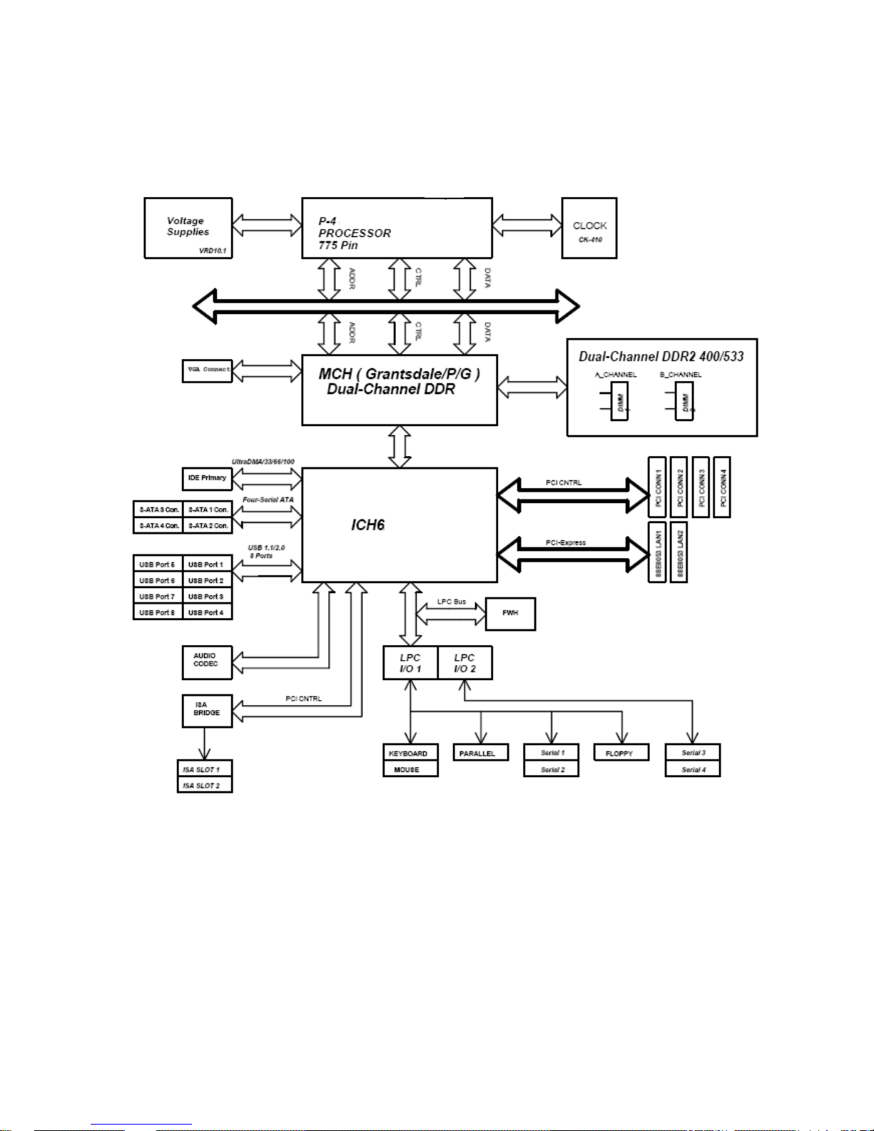
1.4 System Architecture
All of details operating relations are shown in ADE-9021 system block diagram.
ADE-9021 User’s Manual
12 / 49
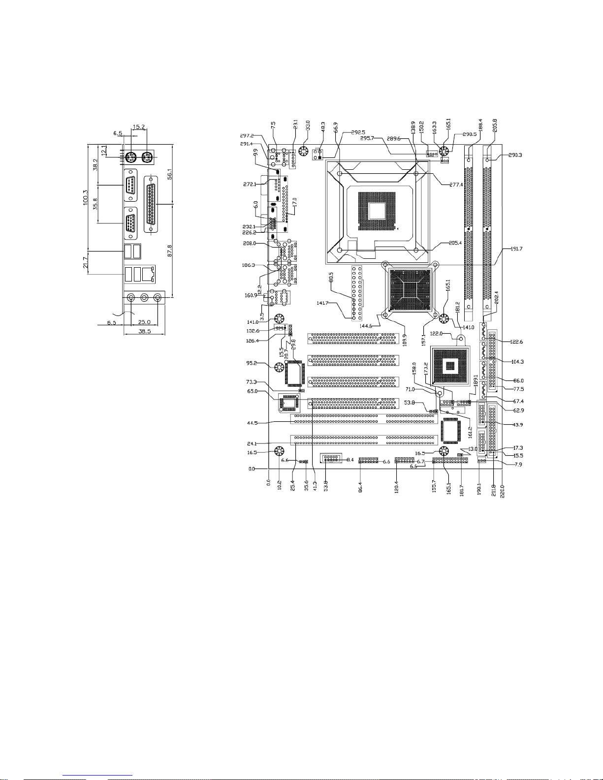
1.5 Dimensions

ADE-9021 User’s Manual
13 / 49
CHAPTER 2
ADE-9021 User’s Manual
14 / 49
2. Hardware Configuration Setting
This chapter gives the definitions and shows the positions of jumpers, headers and
connectors. All of the configuration jumpers on the board are in the proper position. The
default settings shipped from factory are marked with an asterisk ().
In general, jumpers on the board are used to select options for certain features. Some of
the jumpers are designed to be user-configurable, allowing for system enhancement. The
others are for testing purpose only and should not be altered. To select any option, cover
the jumper cap over (SHORT) or remove (NC) it from the jumper pins according to the
following instructions. Here, NC stands for “Not Connect”.
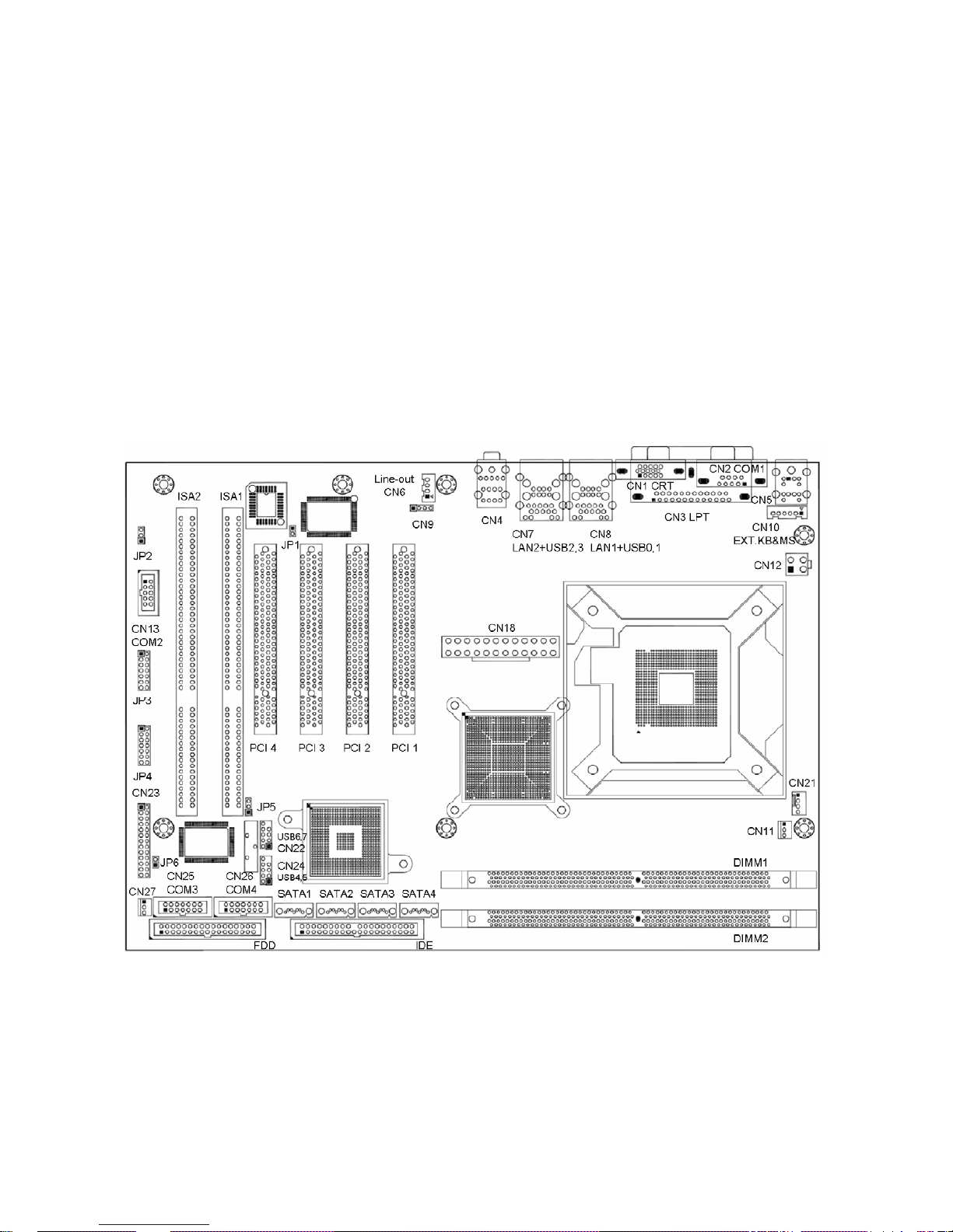
2.1 Board Layout

ADE-9021 User’s Manual
15 / 49
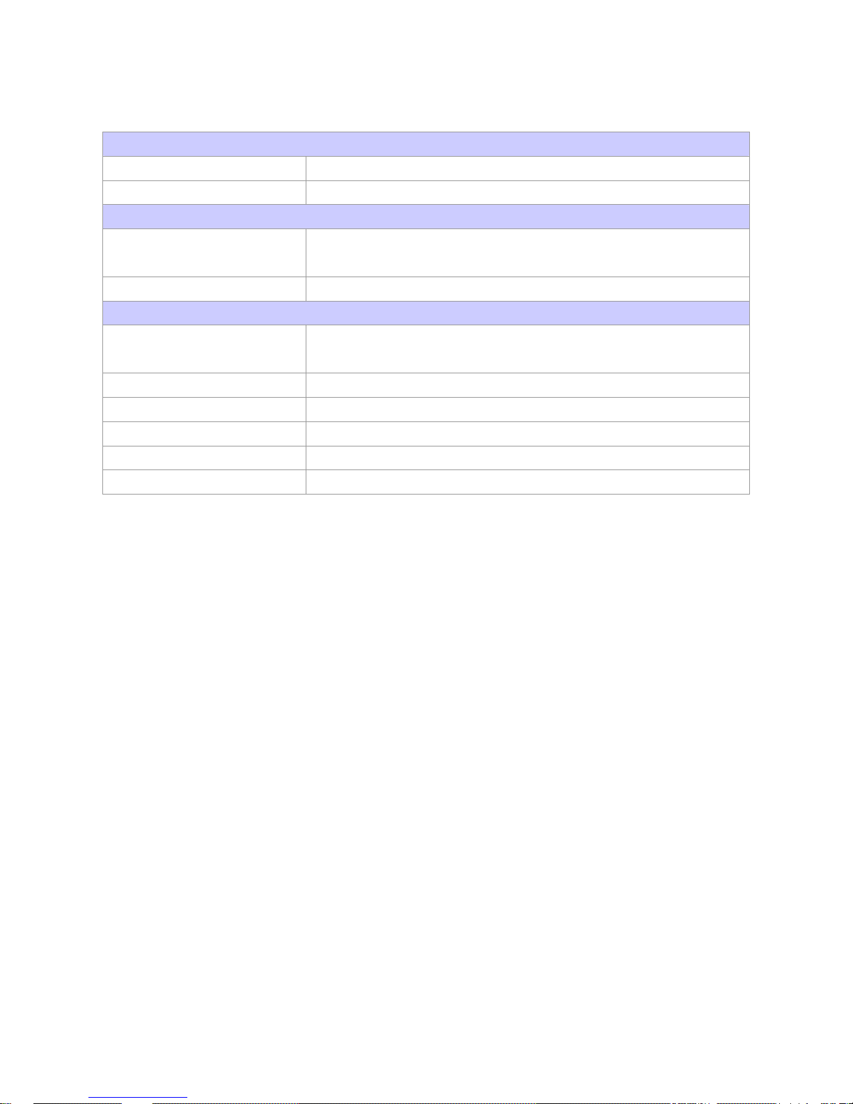
2.2 Jumpers & Connectors
JUMPERS FUNCTION REMARK
JP1
BIOS write protection select 1 x 2 header
JP2
Watchdog Timer setting select 1 x 3 header
JP3
COM4 port setting select 2 x 7 header
JP4
COM3 port setting select 2 x 7 header
JP5
Clear CMOS setting select 1 x 3 header
JP6
Auto power on setting select 1 x 2 header
CONNECTORS FUNCTION REMARK
CN1
D-sub 15-pin VGA connector
CN2
COM1 RS232 connector
CN3
Parallel port connector
CN4
Audio connector
CN5
PS/2 mouse & keyboard connector
CN6
Line out connector 1 x 4 wafer
CN7
LAN2 & USB 2, 3 connector
CN8
LAN1 & USB 0, 1 connector
CN9
CD-In connector 1 x 4 header
CN10
External keyboard & mouse connector 1 x 6 wafer
CN11
Power fan connector 1 x 3 wafer
CN12
ATX 12V power connector
CN13
COM2 RS232 connector 2 x 5 header
CN18
ATX 24-pin power connector
CN21
CPU fan connector 1 x 4 wafer
CN22
Internal USB 6/7 connector 2 x 5 header
CN23
Front panel connector 2 x 13 header
CN24
Internal USB 4/5 connector 2 x 5 header
CN25
COM3 serial port connector 2 x 7 header
CN26
COM4 serial port connector 2 x 7 header
CN27
Chassis fan connector 1 x 3 wafer
SATA1/2/3/4
Serial A T A1/2/3/4 connectors
FDD
Floppy disk connector 2 x 17 header
IDE
Primary IDE connector 2 x 20 header
 Loading...