

Industrial Computers ADE-6040 User Manual

ADE-6040
Intel® Core™ 2 Duo Desktop
Q965 Mini ITX
User’s Manual
Rev. 1.0
2007/02/13
P/N: 600C002604010

ADE-6040 User’s Manual
Copyright
All rights reserved. The information contained in this guide has been validated and
reviewed for accuracy. No patent liability is assumed with respect to the use of the
information contained herein. While every precaution has been taken in the preparation of
this guide, the Manufacturer assumes no responsibility for errors or omissions.
No part of this publication may be reproduced, stored in a retrieval system, or transmitted in
any form or by any means, electronic, mechanical, photocopying, recording, or otherwise,
without the prior written permission of Manufacturer.
Trademark
Intel®, Pentium® and Celeron® are registered trademarks of Intel® Corporation.
Microsoft® and Windows® are registered trademarks of Microsoft Corporation.
All products and company names are trademarks or registered trademarks of their
respective holders.
These specifications are subject to change without notice.
Technical Support
We hope you to get the maximum performance from your products and be willing to help if
running into technical difficulties. For the most frequently asked questions, it’s easily found
answers from the product documentation and usually a lot more detailed, so please take
reference to this manual first. If the answer still can not be found, gather all the information
or questions applying to the problem, and with the product on hand, contact your distributor,
sales representative, or customer service center for technical support. Most problems
reported are minor and able to be easily solved over the phone. In addition, free technical
support is available and always ready to give advices on application requirements or
specific information on the installation and operation of any of our products.
Please have the following information ready before you call:
1. Product name and serial number
2. Description of your peripheral attachments
3. Description of your software (operating system, version, application software, etc.)
4. A complete description of the problem
5. The exact wording of any error messages
2 / 55

ADE-6040 User’s Manual
How to Use This Manual
This manual is written for the system integrator, PC technician and knowledgeable PC end
user. It describes how to configure your ADE-6040 to meet various operating requirements.
The user’s manual is divided into four chapters, with each chapter addressing a basic
concept and operation of the server board.
Chapter 1: Introduction - presents what you have inside the box and gives you an
overview of the product specifications and basic system architecture for the ADE-6040
server board.
Chapter 2: Hardware Configuration Setting - shows the definitions and locations of
Jumpers and Connectors so that you can easily configure your system.
Chapter 3: System Installation - describes how to properly mount the CPU, main memory,
and M-System Flash disk for a safe installation. It will also introduce and show you the
driver installation procedure for the Graphics Controller and Ethernet Controller.
Chapter 4: BIOS Setup Information - specifies the meaning of each setup parameter, how
to get advanced BIOS performance and update to a new BIOS.
Note:
(1) Memory type support dual-channel interleaved mode assuming DDR2, all DIMMs
in a system must be of the same type, the speed in all channels is the speed of
the slowest DIMM in the system.
3 / 55

ADE-6040 User’s Manual
Table of Content
1. Introduction.................................................................................................................8
1.1 Description...........................................................................................................8
1.2 Packing Check List..............................................................................................9
1.3 Specifications....................................................................................................10
1.4 System Architecture..........................................................................................12
1.5 Dimensions........................................................................................................13
2. Hardware Configuration Setting..............................................................................15
2.1 Board Layout .....................................................................................................15
2.2 Jumpers & Connectors.....................................................................................16
2.3 Jumpers/Connectors Setting............................................................................17
2.3.1 RTC CMOS Clear Select (JP1)....................................................................17
2.3.2 Internal Audio for Chassis (AUDIO1)............................................................17
2.3.3 Audio Connector (AUDIO2)..........................................................................17
2.3.4 Auxiliary/CPU/System Connectors (AUX_FAN1, CPU_FAN1, SYS_FAN1). 17
2.3.5 CD-In from CD-ROM (CD1)..........................................................................17
2.3.6 COM1 / COM2 Connector (COM1, COM2)..................................................17
2.3.7 GPIO Connector (GPIO1).............................................................................18
2.3.8 PS/2 Keyboard & Mouse (KBMS1)...............................................................18
2.3.9 Front Side Indicators (PANEL1) ...................................................................18
2.3.10 24-pin ATX Power Connector (PWR1)..........................................................18
2.3.11 4-pin A TX Power Connector (PWR2)............................................................18
2.3.12 Serial ATA 1/2/3/4 Connectors (SATA1, SATA2, SATA3, SATA4) .................18
2.3.13 Internal Speaker Connector (SPK1).............................................................19
2.3.14 LAN 1/2 & USB 1/2/3/4 Connectors (USB2LAN1, USB2LAN2)....................19
2.3.15 Internal USB 5/6/7/8 Connectors (USB1, USB2)..........................................19
2.3.16 VGA Connector (VGA1) ...............................................................................19
4 / 55

ADE-6040 User’s Manual
3. System Installation...................................................................................................21
3.1 Intel® µFC-LGA775 Processor...........................................................................21
3.1.1 Installing Intel® Core™ 2 Duo / Pentium® 4 / Celeron® D CPU......................21
3.2 Installing 1 U Cooler for Intel® µFC-LGA775 Processor.................................. 22
3.3 Main Memory......................................................................................................23
3.4 Installing the Mini-ITX........................................................................................24
3.4.1 Dual Marvell Gigabit Ethernet Controllers....................................................24
3.4.2 Drivers Support ............................................................................................24
4. BIOS Setup................................................................................................................26
4.1 Entering Setup...................................................................................................26
4.1.1 Main Menu....................................................................................................26
4.1.2 Advanced Setting.........................................................................................27
4.1.3 Advanced PCI/PnP Setting...........................................................................41
4.1.4 Boot Settings................................................................................................44
4.1.5 Security Settings ..........................................................................................46
4.1.6 Advanced Chipset Settings ..........................................................................47
4.1.7 Exit Options..................................................................................................52
Appendix A: Watchdog Timer Programming ................................................................54
Appendix B: GPI/O Programming ..................................................................................55
5 / 55

Revision History
Revision Date Comment
Rev.1.0 Apr. 2007 Initial released
ADE-6040 User’s Manual
6 / 55

ADE-6040 User’s Manual
CHAPTER 1
7 / 55

ADE-6040 User’s Manual
1. Introduction
1.1 Description
The leading ADE-6040 Mini-ITX adopts Intel® energy-efficient dual-core processing to fit a
high performance Intel® CoreTM 2 Duo Desktop based in the LGA775 package processors
and compatible for high-end computing applications with PCI-E bus architecture to adapt to
today’s demands and keep complete compatibility with hardware and software designed.
The onboard devices support one PCI Express x16 slot for flexible expansibility of graphics
interfaces, integrated graphics, and onboard dual Marvell Gigabit Ethernet controllers. It’s
beneficial to build up a high performance and fast transmission availability system for VARs,
or system integrators.
The ADE-6040 supports Intel® LGA775 CoreTM 2 Duo Desktop processors in E6000, 600,
500, 400, and 300 sequences via Intel® Q965 and ICH8 chipset integrated GMA 3000
graphics with DVMT 4.0 display memory up to 256 MB for optional dual display function by
VGA/LVDS and VGA/DVI through optional ADD2 card. The board supports two DIMMs up
to 4 GB SDRAM with dual channel DDR2 533/667/800, enhanced onboard four SATA
high-speed data transferring at up to 300 MB/s, integrated Realtek ALC883 7.1 + 2 CH high
definition audio codec. The onboard Super I/O Winbond W83627DHG chipset supports two
RS-232 serial port interfaces, Hardware Monitor function, eight Hi-speed USB 2.0 ports,
and two 6-pin Mini-DIN connectors for PS/2 mouse and keyboard. Besides, one 24-pin
standard connector designed to support ATX power function, and a feature of CPU
overheat protection will provide user more security and stability.
Combing with these outstanding features in the Mini-ITX form factor, ADE-6040 is definitely
the most excellent choice for embedded applications like Network, Point of Sales (POS),
automated KIOSKs, security products, medical instruments, and gaming machines.
8 / 55

ADE-6040 User’s Manual
1.2 Packing Check List
The ADE-6040 Series package includes the following basic items accompany with this
manual.
¾ One ADE-6040 series Mini ITX
¾ One Quick Installation Guide for ADE-6040
¾ Two Serial ATA cables
¾ One Serial port cable for COM2
¾ One USB 2.0 cable
¾ One I/O Shield
¾ One Supporting CD-ROM contains User’s Manual and internal VGA display driver
and Marvell Gigabit Ethernet network controller driver and on board devices
drivers
If any of these items is damaged or missed, please contact your vendor and save all
packing materials for future replacement and maintenance.
9 / 55
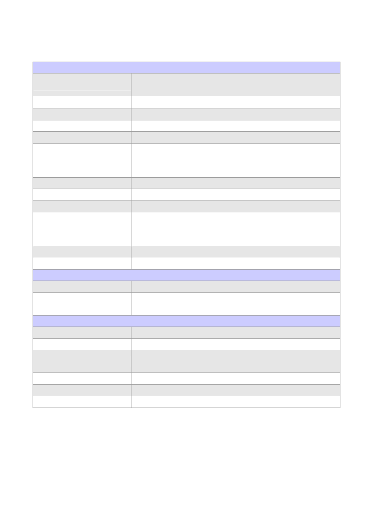
1.3 Specifications
System
ADE-6040 User’s Manual
CPU
FSB 1066/800/533 MHz
BIOS AMI BIOS with 8 Mb SPI Flash EEPROM
System Chipset Intel® Q965 + ICH8
I/O Chip Winbond W83627DHG I/O controller
System Memory
Storage 4 x Serial ATA 300 ports
RAID Optional ICH8R supports RAID 0, 1, 5, 10 function
Watchdog Timer Reset: 1 sec.~255 min. and 1 sec. or 1 min./step
H/W Status Monitor
GPIO On-board programmable 8-bit Digital I/O interface
Intel® Core™ 2 Duo Desktop / Pentium® 4 / Celeron® D processor in the
LGA775 package (E6000, 600, 500, 300 sequences)
2 x 240-pin DIMM sockets support dual channel DDR2 533/667/800
SDRAM
Max. up to 4 GB memory
Monitoring system temperature, voltage, and cooling fan status.
Auto throttling control when CPU overheats.
System automatically restored on recovery of AC power loss.
Expansion 1 x PCI-E x16 interface
MIO
Internal I/O 1 x RS-232, 4 x USB 2.0
Back Panel I/O
Display
Chipset Intel® Q965 Integrated Intel® GMA 3000 graphics
Display Memory Intel® DVMT 4.0 supports up to 256 MB video memory
Resolution
VGA/LCD Interface DSUB-15 connector for VGA output
LVDS Optional Chrontel CH7308 LVDS transmitter by ADD2 card
DVI Optional Chrontel CH7307 DVI transmitter by ADD2 card
1 x VGA, 1 x Audio jack, 2 x RJ-45, 1 x RS-232, 4 x USB 2.0, 1 x KB,
1 x Mouse
Analog display : up to 2048 x 1536 @ 75Hz (QXGA)
Digital CRT/HDTV : up to 1920 x 1080 @ 85 Hz
10 / 55
ADE-6040 User’s Manual
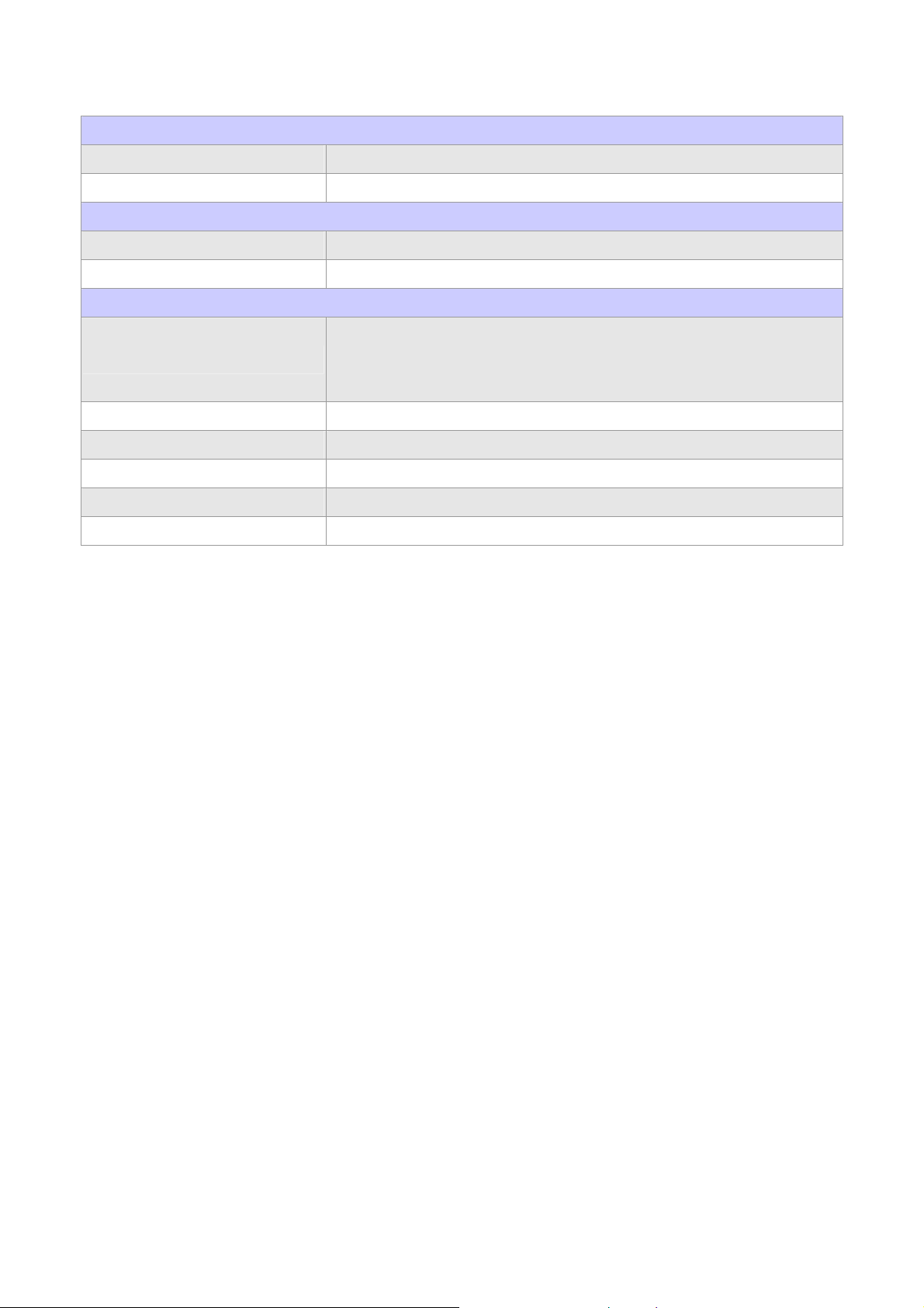
Audio
HDAC Realtek ALC883 7.1 + 2 CH audio interface
Audio Interface Mic in, Line in, CD Audio in, Line out, Rear out and Center/Subwoofer out
Ethernet
Chipset Dual Marvell® 88E8053 PCI Express™ Gigabit Ethernet controllers
Ethernet Interface IEEE 802.3 10BASE-T/100BASE-TX/1000BASE-T
Mechanical & Environmental
+3.3 V @ 3.3 A, +5 V @ 1.9 A, +12 V @ 4 A, 5 Vsb @ 500 mA (w/ Intel®
Power Requirement
Power Type 24-pin ATX power connector, 1x 4-pin ATX 12V power connector
Operating Temperature 0~60°C (32~140°F)
Operating Humidity 0%~90% relative humidity, non-condensing
Size (L x W) 6.69" x 6.69" (170 mm x 170 mm)
Weight 0.94 lbs (0.43 Kg)
Core™ 2 Duo E6700 2.66 GHz & 2 x 512 MB DDR2 800 MHz SDRAM in
Dos Mode)
11 / 55
ADE-6040 User’s Manual
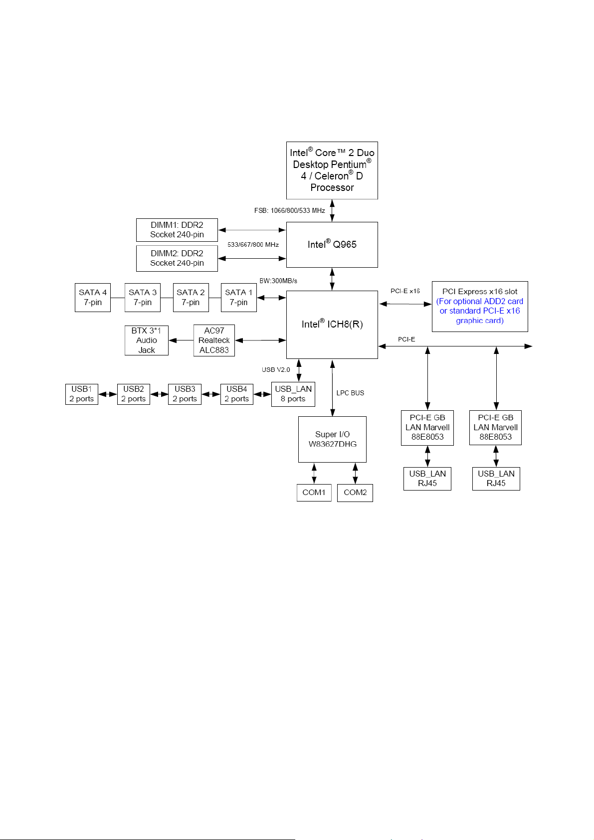
1.4 System Architecture
All of details operating relations are shown in ADE-6040 series system block diagram.
12 / 55
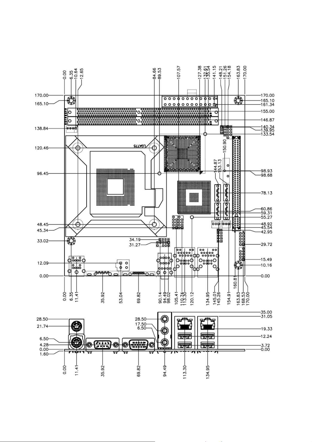
1.5 Dimensions
ADE-6040 User’s Manual
13 / 55
Unit: mm

ADE-6040 User’s Manual
CHAPTER 2
14 / 55
ADE-6040 User’s Manual
2. Hardware Configuration Setting
This chapter gives the definitions and shows the positions of jumpers, headers and
connectors. All of the configuration jumpers on ADE-6040 series are in the proper position.
The default settings shipped from factory are marked with an asterisk ().
In general, jumpers on the Mini ITX are used to select options for certain features. Some of
the jumpers are designed to be user-configurable, allowing for system enhancement. The
others are for testing purpose only and should not be altered. To select any option, cover
the jumper cap over (SHORT) or remove (NC) it from the jumper pins according to the
following instructions. Here, NC stands for “Not Connect”.
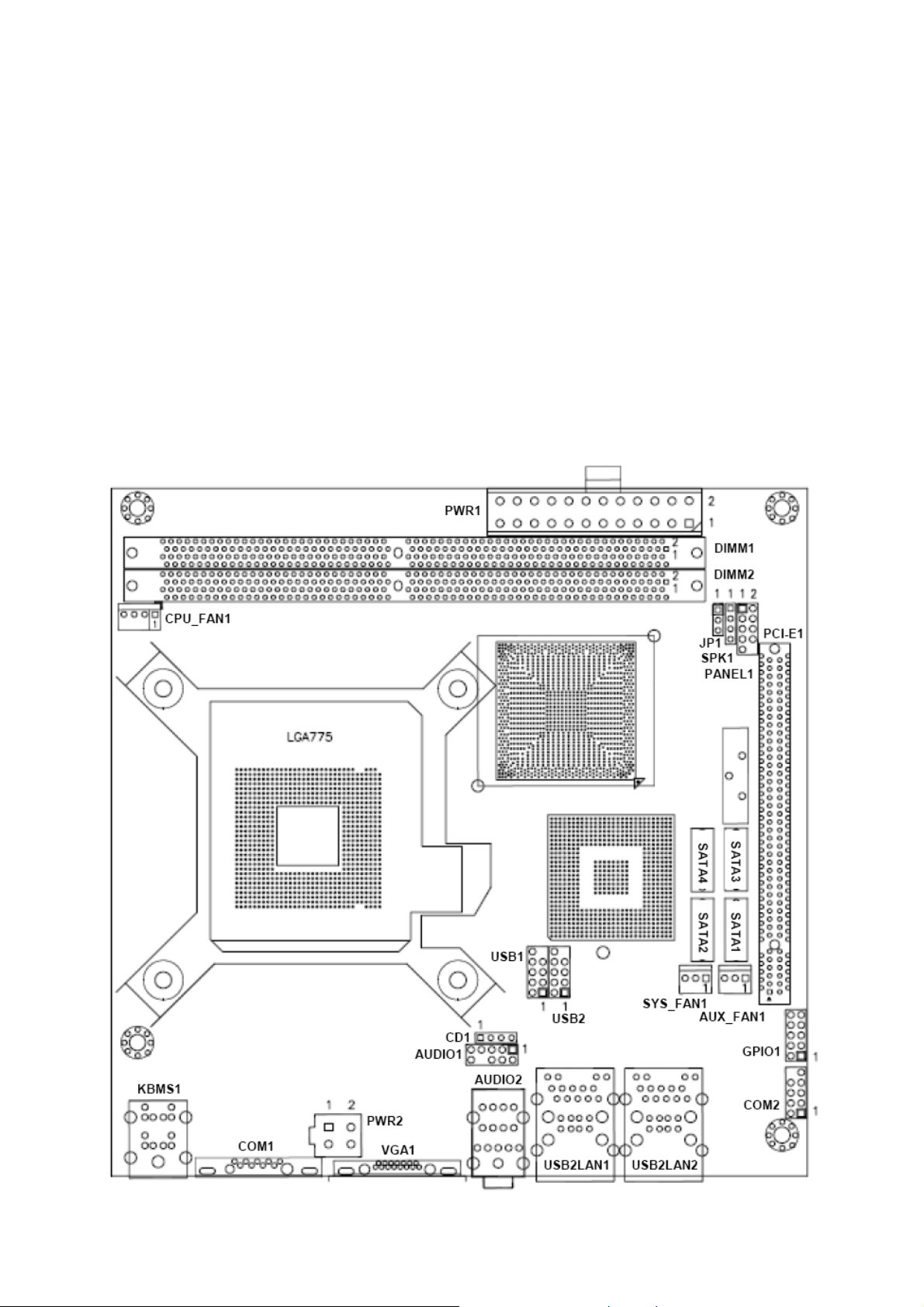
2.1 Board Layout
15 / 55
ADE-6040 User’s Manual
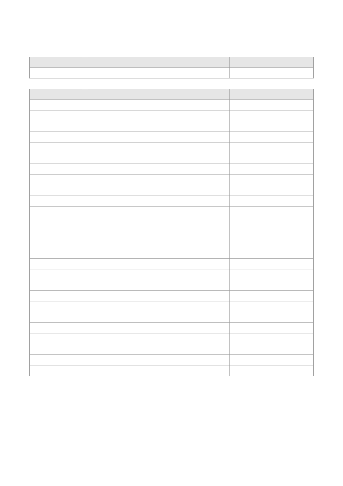
2.2 Jumpers & Connectors
JUMPERS FUNCTION REMARK
JP1
RTC CMOS clear select 3 x 1 header
CONNECTORS FUNCTION REMARK
AUDIO1
AUDIO2
AUX_FAN1
CD1
COM1
COM2
CPU_FAN1
DIMM1, DIMM2
GPIO1
KBMS1
PANEL1
Internal audio for chassis 2 x 5 header
Audio connector Audio jack x 3
Auxiliary fan connector 1 x 3 wafer
CD-In from CD-ROM 1 x 4 header
D-sub 9-pin serial port 1 connector
Serial port 2 connector 2 x 5 header
CPU fan connector 1 x 4 wafer
240-pin DDR2 SDRAM 1 & 2 socket
GPIO connector 2 x 5 header
PS/2 keyboard & mouse connector
Front side indicators:
2 x 5 header
IDE1 active LED (1-3)
System power on LED (2-4)
PCI-E1
PWR1
PWR2
SATA1, SATA2
SATA3, SATA4
SPK1
SYS_FAN1
USB1, USB2
USB2LAN1
USB2LAN2
VGA1
System reset (5-7)
System power on switch (6-8)
PCI Express x16 slot
24-pin ATX power connector
4-pin A TX power connector
Serial ATA 1 & 2 connectors
Serial ATA 3 & 4 connectors
Internal speaker connector 1 x 4 header
System fan connector 1 x 3 wafer
Internal USB 5, 6 & 7, 8 connectors 2 x 5 header
USB 1, 2 & RJ-45 LAN 1 connectors
USB 3, 4 & RJ-45 LAN 2 connectors
D-sub 15-pin VGA connector
16 / 55
ADE-6040 User’s Manual
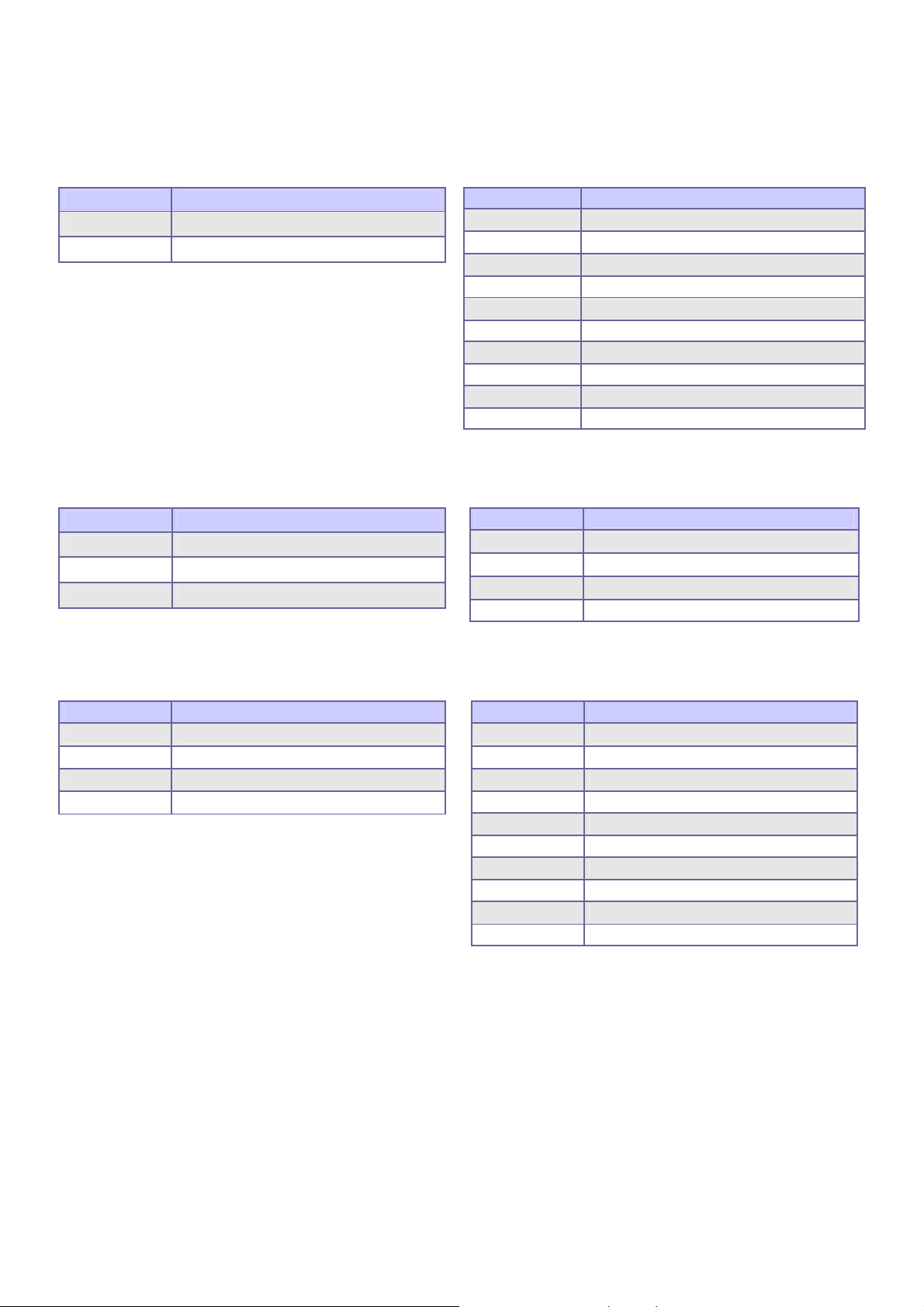
2.3 Jumpers/Connectors Setting
2.3.1 RTC CMOS Clear Select (JP1) 2.3.2 Internal Audio for Chassis (AUDIO1)
PIN No. Description
1-2 Clear CMOS
2-3 Normal operation
PIN No. Description
1 MIC2-L
2 Ground
3 MIC2-R
4 +3.3V
5 LINE2-R
6 Ground
7 Front I/O sense
8 Key
9 LINE2-L
10 Ground
2.3.3 Audio Connector (AUDIO2) 2.3.4 Auxiliary/CPU/System Connectors
(AUX_FAN1, CPU_FAN1, SYS_FAN1)
PIN No. Description
1 (Blue) Line-in
2 (Green) Speaker out
3 (Red) MIC-in
PIN No. Description
1 GND
2 +12V
3 SENSE
4 Control (CPU_FAN1 only)
2.3.5 CD-In from CD-ROM (CD1) 2.3.6 COM1 / COM2 Connector (COM1,
COM2)
PIN No. Description
1 CD-L
2 CD-Ground
3 CD-Ground
4 CD-R
PIN No. Description
1 Data Carrier Detect
2 Received Data
3 Transmit Data
4 Data Terminal Ready
5 Ground
6 Data Set Ready
7 Request To Send
8 Clear To Send
9 Ring Indicator
10 COM2 Key
17 / 55
 Loading...