

Indu-Sol Proftest II, NetTEST II User Manual


Contents
© COMSOFT i
Table of Contents
1 Scope of Delivery............................................................... 1
2 Safety Advice.....................................................................2
3 Introduction ...................................................................... 3
4 Line Tests..........................................................................5
4.1 Line Measurement......................................................5
4.2 LiveList, SlaveDiag, and Level Detection ...................6
4.3 Measurement at the Running Bus ............................... 6
5 NetTEST II Menu Guide .................................................. 7
5.1 Start-Up / Setting in Operation...................................7
5.2 Main Menu.................................................................8
5.2.1 Test without PLC ...............................................9
5.2.1.1 Segment list.............................................10
5.2.1.2 Test with no terminators .......................... 12
5.2.1.3 Test with 1 terminator.............................. 16
5.2.1.4 Test with 2 terminators ............................ 18
5.2.1.5 Generate livelist....................................... 19
5.2.1.6 Slave ident number .................................. 20
5.2.1.7 Slave signal quality.................................. 21
5.2.1.8 Baud rate detection .................................. 22
5.2.2 Test protocol .................................................... 23
5.2.2.1 Create new protocol .................................23
5.2.2.2 Delete ...................................................... 25
5.2.2.3 Display .................................................... 25
5.2.2.4 Transmit.................................................. 25
5.2.2.5 Test company........................................... 26
5.2.2.6 User name list.......................................... 26
5.2.2.7 Customer list............................................27
5.2.2.8 Plant list .................................................. 27
5.2.2.9 Segment list............................................. 28
5.2.3 System configuration........................................ 28
5.2.3.1 RS232 Interface....................................... 28
5.2.3.2 Device properties ..................................... 29
5.2.3.3 Date / Time.............................................. 30

Contents
ii © COMSOFT
5.2.3.4 Basic parameters...................................... 30
5.2.3.5 Load parameters ......................................32
5.2.3.6 Send parameters.......................................32
5.2.3.7 Firmware update...................................... 33
5.2.4 GSD - library ................................................... 33
5.2.4.1 New File.................................................. 33
5.2.4.2 Receive GSD File..................................... 34
5.2.4.3 Delete GSD File....................................... 34
5.2.4.4 Display / Edit........................................... 34
6 Communication with a PC .............................................. 35
6.1 Characteristics of HyperTerminal ............................. 35
6.2 COM Interface Configuration................................... 36
6.3 Receive Test Protocol ............................................... 37
6.4 Send File to NetTEST II........................................... 38
6.5 Send file from NetTEST II to the PC ........................ 39
7 Systems with PROFIBUS -Master Option..................... 40
7.1 Slave line-up ............................................................ 41
7.1.1 Set outputs ....................................................... 43
7.1.2 Read inputs ...................................................... 43
7.1.3 Set value .......................................................... 43
7.1.4 Read value .......................................................43
7.1.5 Read diagnostics .............................................. 43
7.2 Extended master....................................................... 44
7.2.1 Master parameters............................................ 44
7.2.1.1 PROFIBUS Address................................. 45
7.2.1.2 Profibus parameters ................................. 45
7.2.1.3 Copy from segment .................................. 46
7.2.2 Config. with livelist.......................................... 46
7.2.3 COMSOFT Configurator Tool.......................... 47
7.2.3.1 Creation of a configuration ...................... 47
7.2.4 Config. with download ..................................... 49
7.2.5 Slave menu ...................................................... 51
7.2.5.1 New slave ................................................51
7.2.5.2 Copy slave ...............................................54
7.2.5.3 Delete slave.............................................. 54
7.2.5.4 Process slave............................................ 54

Contents
© COMSOFT iii
7.3 Process slave ............................................................55
7.3.1 Edit parameters................................................ 55
7.3.1.1 Profibus address....................................... 56
7.3.1.2 General parameters.................................. 56
7.3.1.3 Prm data .................................................. 56
7.3.1.4 Cfg data................................................... 56
7.3.1.5 DP tag definitions .................................... 56
7.3.2 Line-up ............................................................ 56
7.3.2.1 Line-up.................................................... 58
7.3.2.2 Edit slave address ....................................58
7.3.2.3 Edit slave parameters............................... 58
7.3.2.4 Edit prm. data.......................................... 58
7.3.2.5 Edit cfg. data ........................................... 59
7.3.2.6 Edit xchg. data......................................... 59
7.3.2.7 Show xchg. data....................................... 59
7.3.2.8 Edit DPTag output ................................... 59
7.3.2.9 Show DPTag input................................... 59
7.3.2.10 Show Slave diagnostic............................60
7.3.3 Single DP services............................................ 60
7.4 DPTag definitions .................................................... 61
7.4.1 Display/edit tag................................................ 62
7.4.2 Create new tag ................................................. 63
7.4.3 Delete tag......................................................... 63
8 System with Online Functionality .................................. 64
8.1 Baud rate detection................................................... 66
8.2 Generate livelist ....................................................... 67
8.3 Rotation time............................................................ 68
8.4 Signal level measurement......................................... 69
8.4.1 Measurement with livelist ................................ 70
8.4.2 Measurement with filter ................................... 70
8.4.2.1 Define filter ............................................. 71
8.5 Signal level summary list..........................................72
8.6 Event log.................................................................. 73
8.7 Event count .............................................................. 74
8.8 Diagnostic event....................................................... 75
8.9 Settings .................................................................... 76

Contents
iv © COMSOFT
9 Operation of the Battery Charger.................................. 77
10 Tips & Tricks................................................................ 78
10.1 Cable Lengths in PROFIBUS Segments.................. 78
10.2 Segment Cascading ................................................ 78
10.3 Use of Stub Lines....................................................79
11 Pin Assignment.............................................................. 80
12 Key Allocation............................................................... 81
13 Problematic Slaves........................................................ 82
14 Frequently Asked Questions: FAQ............................... 83
15 Technical Data .............................................................. 85
15.1 NetTEST II............................................................. 85
15.2 Plug Charger .......................................................... 86
Tables
Table 1 Segment length specification ...............................78
Table 2 Pin assignment of D-SUB 9 connector................. 80
Table 3 Key allocation NetTEST II .................................81
Table 4 Technical data NetTEST II................................. 86
Table 5 Technical data Plug charger ................................86

Contents
© COMSOFT v
Figures
Figure 1: Connection NetTEST II in the cable thread.....5
Figure 2: Screen ‘Start-up’..............................................7
Figure 3: Screen ‘Main menu’.........................................8
Figure 4: Screen ‘Test without PLC’ ...............................9
Figure 5: Screen ‘Segment list’ .....................................10
Figure 6: Screen ‘Segment configuration’ .....................10
Figure 7: Screen ‘Test with no term’ .............................13
Figure 8: Screen after ‘Test with no term’ ..................... 13
Figure 9: Screen after ‘Test with 1 term.'.......................16
Figure 10: Screen after ‘Test with 2 term.’...................... 18
Figure 11: Screen ‘Generate livelist’ ............................... 19
Figure 12: Screen ‘Slave ident number’...........................20
Figure 13: Screen ‘Slave signal quality’ ..........................21
Figure 14: Screen ‘Baud rate detection’........................... 22
Figure 15: Screen ‘Test protocol’ ....................................23
Figure 16: Selection menu ‘Test protocol’....................... 23
Figure 17: Screen ‘Test protocol with PLC’.....................24
Figure 18: Screen ‘Test Company’ ..................................26
Figure 19: Screen ‘User name list’ .................................. 26
Figure 20: Screen ‘Customer list’ .................................... 27
Figure 21: Screen ‘Plant List’..........................................27
Figure 22: Screen ‘System configuration’........................ 28
Figure 23: Screen ‘Device properties’..............................29
Figure 24: Screen ‘License code’..................................... 29
Figure 25: Screen ‘Basic parameters’ .............................. 30
Figure 26: Screen ‘GSD - library’ ...................................33
Figure 27: Connection Setting via COM1........................35
Figure 28: Characteristics of the serial interface..............36
Figure 29: "Start-up" Screen with the PB-Master ............40
Figure 30: Screen ‘Line test’...........................................40
Figure 31: Screen ‘Profibus master mode’....................... 41
Figure 32: Screen ‘Slave line-up’ ....................................41
Figure 33: Screen ‘Slave line-up’ ....................................42
Figure 34: Screen ‘Extended master’............................... 44
Figure 35: Screen ‘Master parameters’............................ 44
Figure 36: Screen ‘Other address’................................... 45
Figure 37: Entry mask ‘Master configuration’................. 45
Figure 38: Screen ‘Config. with livelist’..........................46
Figure 39: Screen ‘context menu in the Configurator’ .... 47
Figure 40: Slave –Configuration Dialogue.......................48
Figure 41: Screen ‘Receive CFG file’ ..............................49
Figure 42: Download Configurator -Tool dialogue .........50

Contents
vi © COMSOFT
Figure 43: Confirmation Screen ‘Receive CFG file’ ........ 50
Figure 44: Screen ‘Slave menu’.......................................51
Figure 45: Selection menu ‘New address’........................51
Figure 46: Entry mask ‘Parameter’..................................52
Figure 47: Entry mask ‘User prm’...................................53
Figure 48: Entry mask ‘Cfg data’.................................... 53
Figure 49: Selection menu ‘Copy slave’ ..........................54
Figure 50: Screen ‘Process slave’ ....................................55
Figure 51: Screen ‘Edit parameter’..................................55
Figure 52: Screen ‘Line up’.............................................58
Figure 53: Screen ‘Single DP services’............................60
Figure 54: Screen ‘Tag(s) use/modify’.............................61
Figure 55: Selection menu ‘Display/edit tag’................... 62
Figure 56: Entry mask ‘Tag data’.................................... 62
Figure 57: "Start-up" Screen with Online Function .........64
Figure 58: Screen Line test..............................................64
Figure 59: Screen Test with PLC..................................... 65
Figure 60: Baud rate detection......................................... 66
Figure 61: Generate Slave livelist.................................... 67
Figure 62: Generate Master livelist..................................67
Figure 63: Rotation time .................................................68
Figure 64: Signal level measurement............................... 69
Figure 65: Selection menu Signal level measurement ...... 70
Figure 66: Measurement with filter ................................. 70
Figure 67: Screen ‘Filter name’....................................... 71
Figure 68: Screen ‘DP-Slave list’ .................................... 71
Figure 69: Screen ‘DP-Slave sorting’ .............................. 72
Figure 70: Screen ‘Signal level summary list’ ................. 72
Figure 71: Screen ‘Event log’.......................................... 73
Figure 72: Screen ‘Event count’......................................74
Figure 73: Screen ‘Diagnostic event’............................... 75
Figure 74: Screen ‘Settings’............................................76

Scope of Delivery
© COMSOFT 1
1 Scope of Delivery
Included in the scope of delivery of the NetTEST II service
case are the following items:
• one PROFIBUS NetTEST II cable tester
• two battery packs NiMH 4,8 V/1500 mAh
• one battery charging holder
• one 230 VAC plug-in battery charger
• power supply adapter
• one PROFIBUS Stub line 0.15 m, DB9M / DB9M
• one RS232 Cable connector DB9M / DB9F
• one PROFIBUS Y-Cable, 0.15 m, DB9M / 2xDB9F
• one PROFIBUS Bus disconnector, DB9M / DB9F
• one Gender Changer DB9M / DB9F (mounted on
NetTEST II)
• one Gender Changer DB9M / DB9M
• one Gender Changer DB9F / DB9F
• one Transport case
• one User’s guide
• one COMSOFT Configurator-Tool
(for DP Master Option)

Safety Advice
2 © COMSOFT
2 Safety Advice
The NetTEST II may only be operated with licensed NiCd
batteries or NiMH batteries.
• Do not immerse battery pack under water or expose it to
open fire.
• Do not open battery pack and do not try to replace
individual battery cells.
• Do not dispose of faulty battery packs with normal
household garbage!
• The battery pack could warm up during charging. This is
a normal process and not dangerous.
• Do not use other chargers than supplied and specified by
COMSOFT, the batteries could otherwise be damaged.
• Do not use NetTEST II in surroundings with explosion
hazard.
In case that water or other liquids should have
penetrated your NetTEST II, remove the battery pack or
the power supply adapter. Then have your NetTEST II
checked by our Service Department. The same applies
for the battery charging holder and the plug-in battery
charger.

Introduction
© COMSOFT 3
3 Introduction
With the PROFIBUS NetTEST II you have acquired a highquality tool for the examination of RS485-based PROFIBUS
segments.
COMSOFT’s aim is to provide its users with a valuable tool
for an easy check, without extensive test methods of the
correct cabling of their PROFIBUS net and to document this.
Furthermore, the search for errors in already installed
PROFIBUS systems shall be as easy as possible. We guess that
we reached this target with NetTEST II,the 2
nd
generation of
COMSOFT PROFIBUS test tools.
Therefore it goes without saying that with NetTEST II,the
checks can be run with connected and disconnected devices. It
does not matter if the devices are powered or not. For physical
testing you only have to ensure that there is no active Master
(PLC) polling the bus.
Besides the standard cable test, i.e. the verification of the lines
regarding cable length, line impedance, correct termina-
tion, cable rupture, broken shield, stub lines, inhomogeneous cable segments, mixed up cables, short circuits,
faulty PROFIBUS connectors and faulty device connections, NetTEST II disposes of PROFIBUS DP specific test
functions. So, e.g. the livelist and the Slave Ident Number
are indicated, also the transmission level of the Slaves
connected to the bus is detected per device. Furthermore,
NetTEST II detects the current baud rate at the running bus.
During the baud rate scan a signal analysis indicates faults or
errors in the cabling.

Introduction
4 © COMSOFT
Apart from these basic functions the following options are
available for NetTEST II:
• DP Master Option
With the DP Master Option the set into operation of
DP Slaves is possible without the PLC. The
DP Slaves can be configured with the COMSOFT
PROFIBUS configuration tool based on the DP Slaves
appropriate GSD file.
• Online-Function
This function performs a detailed analysis of the
telegram traffic and the physical state of the
PROFIBUS line.
To make installation checks and error retrieval as easy as
possible, we divided this manual into the following sections:
• Line tests
• Menu guide
• PC connection
• DP Master functionality (optional)
• Online functionality (optional)
• Tips & Tricks
We hope that we can give you with our test tool NetTEST II
and this manual all necessary means for a faultless function of
your PROFIBUS plant. In case of queries, please contact our
hotline, we will be pleased to help you with our advice.
Line Tests
© COMSOFT 5
4 Line Tests
4.1 Line Measurement
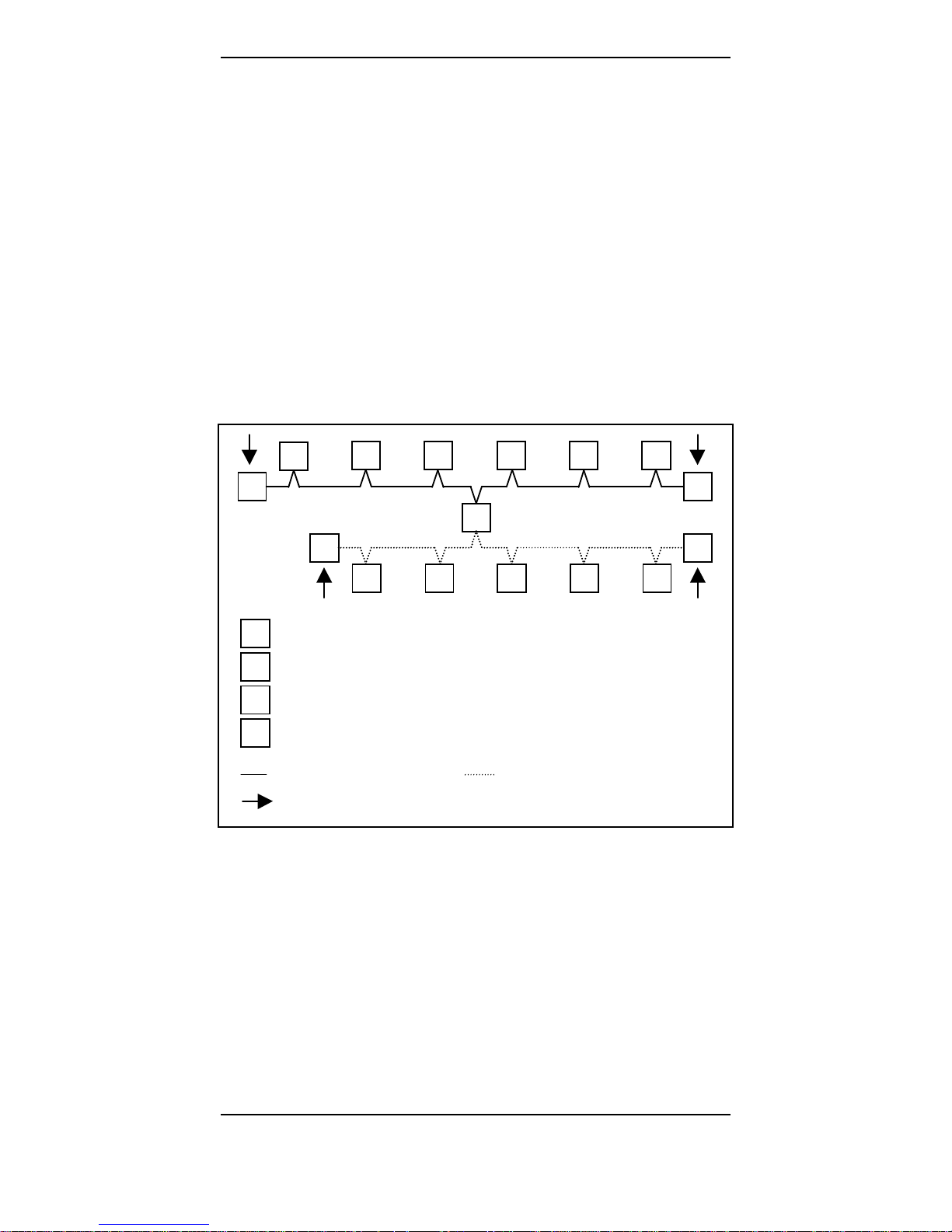
Generally, measurements regarding line physics can only be
made from one end of the PROFIBUS line. If you try to
measure from any other place within the segment, you will
obtain faulty results.
Furthermore please make sure that during measurements no
Master is polling the bus or is sending tokens. Pure
PROFIBUS DP Slave devices as well as e.g. repeaters and
optical couplers must not be disconnected from the bus. An
oversight over the possible measuring points in line segments
for line measurement is depicted below:
S
M
T
R
T
S S S S
S S S S S
TT
T
M
S
R
=Terminato
r
=Maste
r
=Slave
= Repeater / Segment coupler / Optical coupler
= Segment 1 = Segment 2
= Measuring point
Figure 1: Connection NetTEST II in the cable thread

Line Tests
6 © COMSOFT
4.2 Livelist, SlaveDiag, and Level Detection
To make detections as easy as possible, the generating of the
livelist, the Slave diagnosis and Slave-related transmission
level detection should be effected as well from the bus end.
However, you can also make these from any other available
measuring point within one segment. Here, please observe that
the function of the livelist and of the SlaveDiag also work via
a repeater, segment coupler or optical coupler. The level
detection of a Slave connected via such a device reflects only
the transmission level of the repeater and not the one of the
detected Slaves!
4.3 Measurement at the running bus
The measurements at the running bus are limited to an
indication of the current baud rate, as well as of the general
transmission level quality of the connected Slaves. By this
means, a qualitative evaluation of the level on the bus line is
made. If the test tool shows reflections, the reasons for those
can only be found with the line detection, which implies that
the Master(s) is / are being turned off.
NetTEST II Menu Guide
© COMSOFT 7
5 NetTEST II Menu Guide
5.1 Start-Up / Setting in Operation
Check the completeness of the scope of delivery and charge
batteries before first setting in operation. Remove the battery
by gently pressing the locking and at the same time pulling
down the battery placed at the rear lower side of the
NetTEST II. Now place the battery into the charging holder,
and check the loading procedure by means of the LED in the
battery charger. For detailed information refer to the enclosed
documentation of the battery charger. Remove the battery from
the charging holder and push it onto the NetTEST II until
you can hear it snapped in.
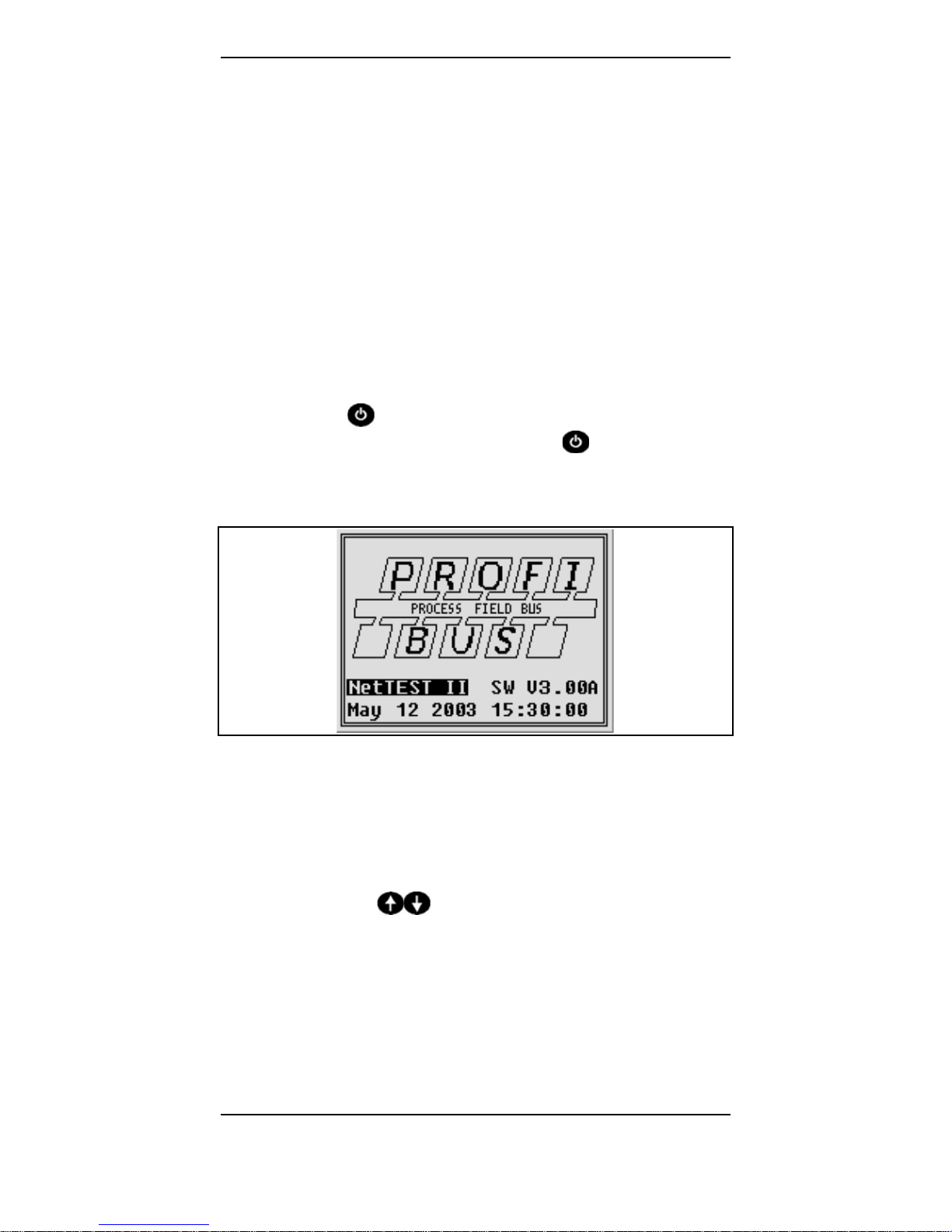
Now push the
key approx. 1s, until the PROFIBUS logo
appears on the screen. Then release the
key. Besides the
PROFIBUS logo, the firmware version and date appears for
approx. 2s.
Figure 2: Screen ‘Start-up’
Now the main menu is displayed automatically. The test tool is
ready for operation. With various different text outputs the
display is too small, this will be indicated by "^^" at the right
upper and "vv" at the right lower corner of the text. By
pressing the keys
you may scroll up or down in the
text.
NetTEST II Menu Guide
8 © COMSOFT
5.2 Main Menu
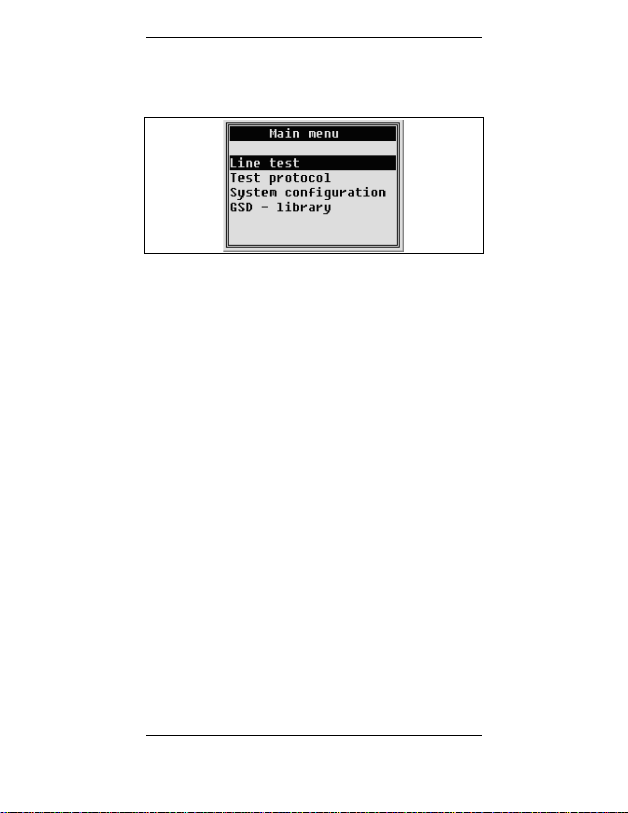
The main menu automatically appears on the display after
having started the NetTEST II.
Figure 3: Screen ‘Main menu’
The main menu comprises the following submenus:
• Line Test
• Test without PLC
Stepwise check of cabling and test of DP Slaves,
without protocol generation.
• PROFIBUS Master mode (optional)
Set into operation of DP Slaves without PLC.
• Test with PLC (optional)
Detailed analysis of the telegram traffic and the
physical state of the PROFIBUS line.
• Test Protocol
• Test without PLC
Like Line Test – Test without PLC, however, the
results of all tests are stored in a test protocol for
documentation purposes.
• Test with PLC (optional)
Like Line Test – Test with PLC, however, the results
of all tests can be stored in a test protocol for
documentation purposes.
• System Configuration
For all device-specific settings.
• GSD - library
Submenu for the administration of GSD files.
NetTEST II Menu Guide
© COMSOFT 9
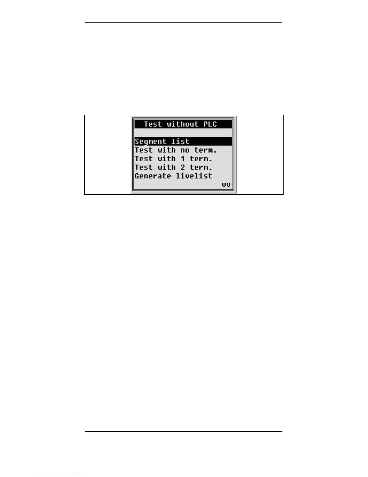
5.2.1 Test without PLC
The menu Test without PLC serves for stepwise physical
analysis of lines. This means that the test can be executed as
often as desired. Some tests are based on the reference data of
the preceding test, so that this one must be run beforehand.
The individual items are interlocked, so that wrong operation
is impossible. For tests run under this menu, no protocol is
made out.
Figure 4: Screen ‘Test without PLC’
For a line test, at first the design parameters for the
PROFIBUS segment that has to be checked must be indicated.
These indications are necessary, so that, e.g. the PROFIBUS
DP specific measurements at the line segment may be
executed with the real bus settings used in your plant. The
settings are made in the submenu Segment list.
As soon as a option is activated (DP Master or OnlineFunction), the Line test menu appears under Test
without PLC.
NetTEST II Menu Guide
10 © COMSOFT
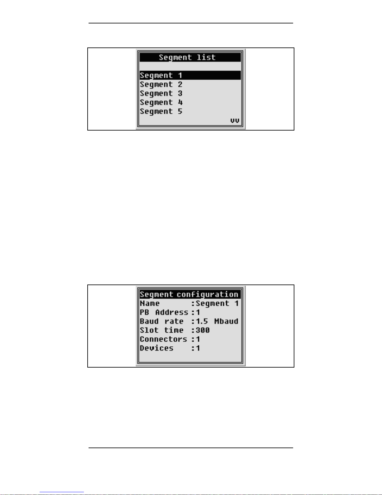
5.2.1.1 Segment list
Figure 5: Screen ‘Segment list’
Under Segment list, segment-specific data are stored serving
as basis for the following measurements. The data are stored
in the data base for line segments under the assigned segment
name. From there, they can be used as basis for both
individual tests and the creation of test protocols. Indications
must be made as to the points listed below:
• Name of line segment (max. 30 characters)
• PROFIBUS baud rate (9.6 Kbit/s - 12 Mbit/s)
• PROFIBUS address for master operation of NetTEST II
(0-126)
• PROFIBUS slot time tslot (300-5000)
Figure 6: Screen ‘Segment configuration’

NetTEST II Menu Guide
© COMSOFT 11
The PROFIBUS baud rate, address and slot time are necessary
for the parameterization of the installed PROFIBUS Master.
With these settings, the tests Generate livelist, Slave i dent
number, as well as Slave signal quality are executed.
Moreover, indications regarding number of:
• Connectors (only number of 12 Mbit/s plugs!)
• Devices (all devices with PROFIBUS plug, or connected
cable)
Connected devices and 12 Mbit/s PROFIBUS plugs
considerable change by their inductivity resp. capacity the
measuring abilities and characteristics for the NetTEST II.In
order to keep these measuring insecurities in a tolerable scale,
please indicate before each measurement the number of
installed 12 Mbit/s plugs as well as the number of the devices
connected to the bus. Please only indicate the plugs which
dispose of incorporated direct-axis inductances. Devices stands
for all units connected to a bus segment. This applies to
Master and Slaves as well as to net components like segment
couplers, repeaters, optical couplers etc.
Once the data are stored in the data base, they can always be
used for new tests. The data in this data base cannot be
deleted, only changed by overwriting. In order to have enough
spare capacity for this function, 20 memory locations are
available. The respective memory locations can be reached by
actuating the
or the key.

NetTEST II Menu Guide
12 © COMSOFT
5.2.1.2 Test with no terminators
At the beginning of each test, the Test with no term. must be
carried out. For this, the NetTEST II must be connected to
one end of the PROFIBUS segment. Now the user makes sure
that all bus termination resistors (terminators) in the bus
segment are switched off resp. removed. Furthermore, no
Master may send data via the bus. Then the Test with no term.
can be carried out. If, by accident, a bus terminator or Master
should be active in the segment, the NetTEST II recognizes
and indicates this at once. Only if no more resistance in the
thread is activated and all Masters are deactivated, the
NetTEST II informs about:
• Line impedance
• Line length (segment length)
Detections in segments with PROFIBUS plugs with a
disconnection function can be tricky. If, e.g., in the
middle of a segment, the terminator of such a plug is
activated, the NetTEST II recognizes it, if it is measured
from the entrance side. However, if the measurement is
made from the other end of the plug, measuring is made
into the open end and a cable length, shorter than the one
expected, is indicated. Therefore please check very
thoroughly if all bus terminators are switched off.
Another possibility of finding such a plug is measuring
from the other side of the bus.
NetTEST II Menu Guide
© COMSOFT 13
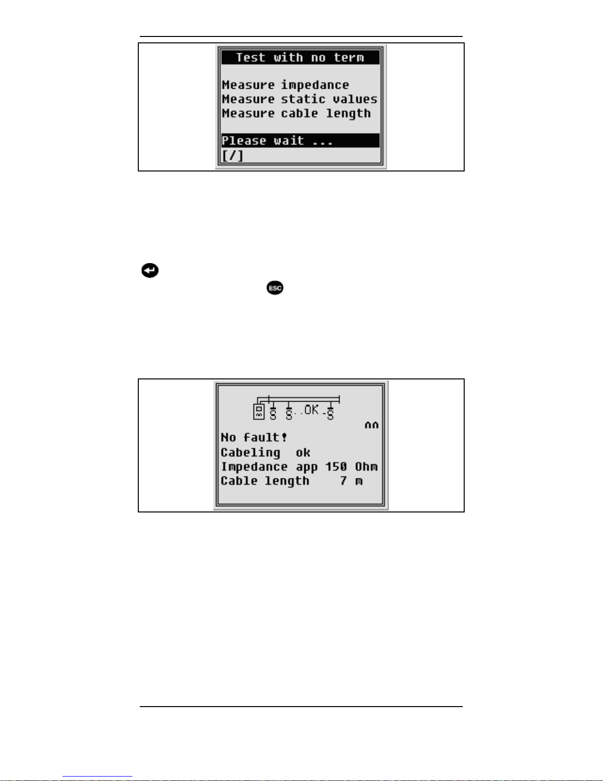
Figure 7: Screen ‘Test with no term’
The Test with no term. lasts for a few seconds. The duration
depends on the cable length. To show the user that the system
is still working, a star bar appears on the lower left hand side
of the display as progress indication. Terminate the test with
. Upon conclusion the result will be displayed. Attention: If
you quit the test with
,theTest with 1 term. cannot be
executed any more, as the just scanned data were deleted.
If no error is detected on the PROFIBUS segment, a "positive
acknowledgement" message will appear, displaying the cable
impedance and cable length according to the following figure.
Figure 8: Screen after ‘Test with no term’
The following error indications, that impede correct length
and impedance measurement, may occur:
• "No error: Impedance not detected": Cable length for the
impedance measurement is too short.
• "Error: No length measured": Cable length is either too
short for length measurement or there is no cable
connected.
• "Error: A<->shield / B<->shield short circuit":Thereis
a low ohmic resistance between signal wire and shield.

NetTEST II Menu Guide
14 © COMSOFT
• "Error: A<->B Short circuit or unpowered termination":
There is a low ohmic resistance between the signal wires,
which might be caused for example by a bus termination
without power supply.
• "Error: A<->B Irregularity, wrong termination or illegal
termination ": There is an unacceptable ohmic resistance
between the signal wires, that stands in no relation to the
magnitude of a bus termination either with or without
power supply. The cause might be for example an
incorrectly connected bus termination.
• "Error: A<->B Terminator": There is a powered bus
termination (possibly along the line), which impedes
impedance and length measurement.
• "Error: A<->shield / B<->shield high imp. fault":There
is a high ohmic resistance between signal wire and shield.
• "Error: A<->B Capacitive load, junction or Impedance
changes": There is a capacitive resistance between the
signal wires, which might be caused by a PROFIBUS
device with unauthorized bus coupling, a branch or switch
over to a inadmissible cable type.
• "Error: Possible broken line of shield / of signal line A/B
distance XX m": Result of the length measurement is
significantly different for the various lines and shields.
• "Error: uncertain situation / possibly broken line of
shield or of signal line A/B. Please repeat measurement
at the opposite segment-end": Result of the cable length
measurement for the various different lines and shields is
so different, that no specific statement about the respective
line segment is possible. Should the measurement on the
other line end give correct results, then the measurement
may be considered o.k. In particular, this effect may be
observed with cable coils or cable drums in the
PROFIBUS network.

NetTEST II Menu Guide
© COMSOFT 15
With each of these error messages there may be an
indication of a distance. Some errors (e.g. invalid
termination) do not give conclusive information about the
distance.
Moreover, all error messages may also include the indication
"uncertain error". This may be indicated, if the cause of the
error could be detected only roughly, thus permitting only an
error estimation.
Also with uncertain error situations, the PROFIBUS
segment has problems in any case, even if the
measured error is relatively small. Due to EMV and
high baud rates (≥1.5 Mbit) this may lead to severe
communication problems.
An effective method for determining errors in their
position is to divide the segment into several subsegments, and to submit them to separate
examinations.
All error indications are also displayed with the key.
NetTEST II Menu Guide
16 © COMSOFT
5.2.1.3 Test with 1 terminator
Prior to the Test with 1 term.,inanycasetheTest with no
term. must be completed. If this was not made, the user is
being informed about this and can immediately make up for
this test. For the Test with 1 term., the terminator at the bus
end opposite to the NetTEST II must be switched on and set
under current. With a DP Slave unit or another passive bus
participant, the plug can be connected directly, the terminator
added and the unit switched on. If the unit at the end of the
line segment is a PROFIBUS Master, take care that the bus
participant does not actively send data onto the bus. This can
e.g. be realized by a bus disconnector. Via the bus
disconnector, the bus terminator in the PROFIBUS plug is
supplied with power, but the bus line is interrupted by a
mechanical switch in direction to the line segment.
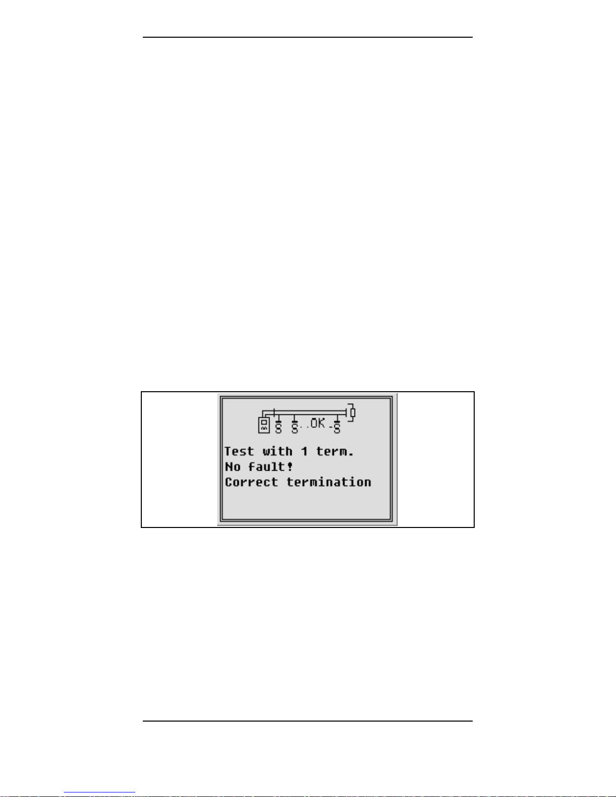
Upon conclusion of the test the result will be displayed on the
screen.
If no error is detected with the Test with 1 term on the
PROFIBUS segment, a "positive acknowledgement" will
appear, according to the following figure.
Figure 9: Screen after ‘Test with 1 term.'

NetTEST II Menu Guide
© COMSOFT 17
In case of errors, the following error messages may be
displayed:
• "Error: no termination or switch defect": No valid
termination could be detected.
• "Error: Your terminator is not at the far end of the
segment !": Contrary to the instruction the terminator was
switched at the near segment end.
• "Error: A<->B twisted": Mix up of signal lines.
• "Error: A<->shield / B<->shield short circuit ":Thereis
a low ohmic resistance in the cable between signal wire
and shield.
• "Error: A<->B short circuit or bus terminal without
power supply": There is a low ohmic resistance in the
cable between the signal wires.
• "Error: A<->B Irregularity, Wrong termination or illegal
termination": There is an inadmissible ohmic resistance
between the signal wires, that stands in no relation to the
magnitude of a bus termination either with or without
power supply, for example caused by a wrongly connected
bus termination.
The Test with 1 term. must also be terminated by the
key
in order to be able to execute the following test.
NetTEST II Menu Guide
18 © COMSOFT
5.2.1.4 Test with 2 terminators
Following the Test with 1 term., the Test with 2 term. is
started. Here it is checked if the bus terminator at the line end
of the NetTEST II was switched on additionally. For this test,
the terminator must also be supplied with power. This can
easily be done from the last unit in the segment. If this should
be a Master which cannot be made passive, the data line has
again to be disconnected from the segment via a bus
disconnector.
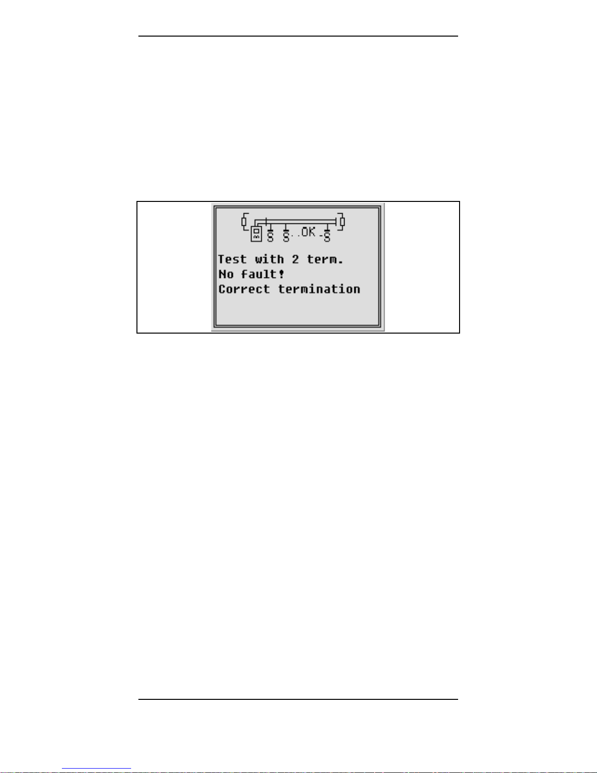
Figure 10: Screen after ‘Test with 2 term.’
If the Test with 2 term. was terminated successfully, it can be
taken for granted that the cabling in the segment was done
correctly. If during the test with NetTEST II an error should
has been detected, this would be depicted on the display by a
graphic and text indication.
Possible error messages are described in detail in chapters
5.2.1.2and 5.2.1.3
NetTEST II Menu Guide
© COMSOFT 19
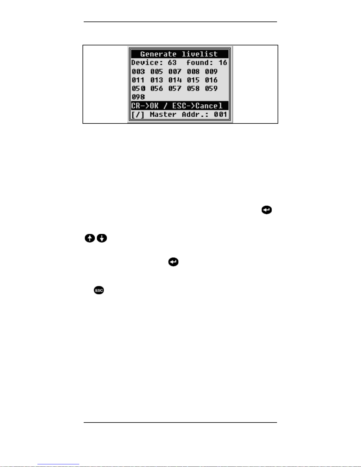
5.2.1.5 Generate livelist
Figure 11: Screen ‘Generate livelist’
In the menu Generate livelist, NetTEST II scans all possible
bus addresses from 0....126 for PROFIBUS DP Slave
participants. For this, a FDL request is effected several times
on each address. If a device answers with OK, its bus address
appears on the display. The unit counter is incremented by
one. To ensure that also extremely slow units are recognized,
the test takes approx. 30 seconds. Should all connected units
already be recognized, the user can truncate the test with
.
Should there be more units than depictable on one display
screen, the user can scroll through after the test with
keys.
To be able to execute further tests, Generate livelist must by
all means be terminated by
. Only then the recognized units
are registered in the internal memory, so that for these in the
following test, a Slave_Diag_Req can be run. If the test is quit
by
, no slave diagnosis can be executed afterwards!

NetTEST II Menu Guide
20 © COMSOFT
5.2.1.6 Slave ident number
Figure 12: Screen ‘Slave ident number’
Via the Slave ident number menu, the Ids for a better
assignment of the DP Slave addresses to the unit type can be
indicated. Here, a Slave_Diag_Request is executed on the
respective device, and this returns in its answer the ident
number. This will then be indicated behind the Slave address.
NetTEST II Menu Guide
© COMSOFT 21
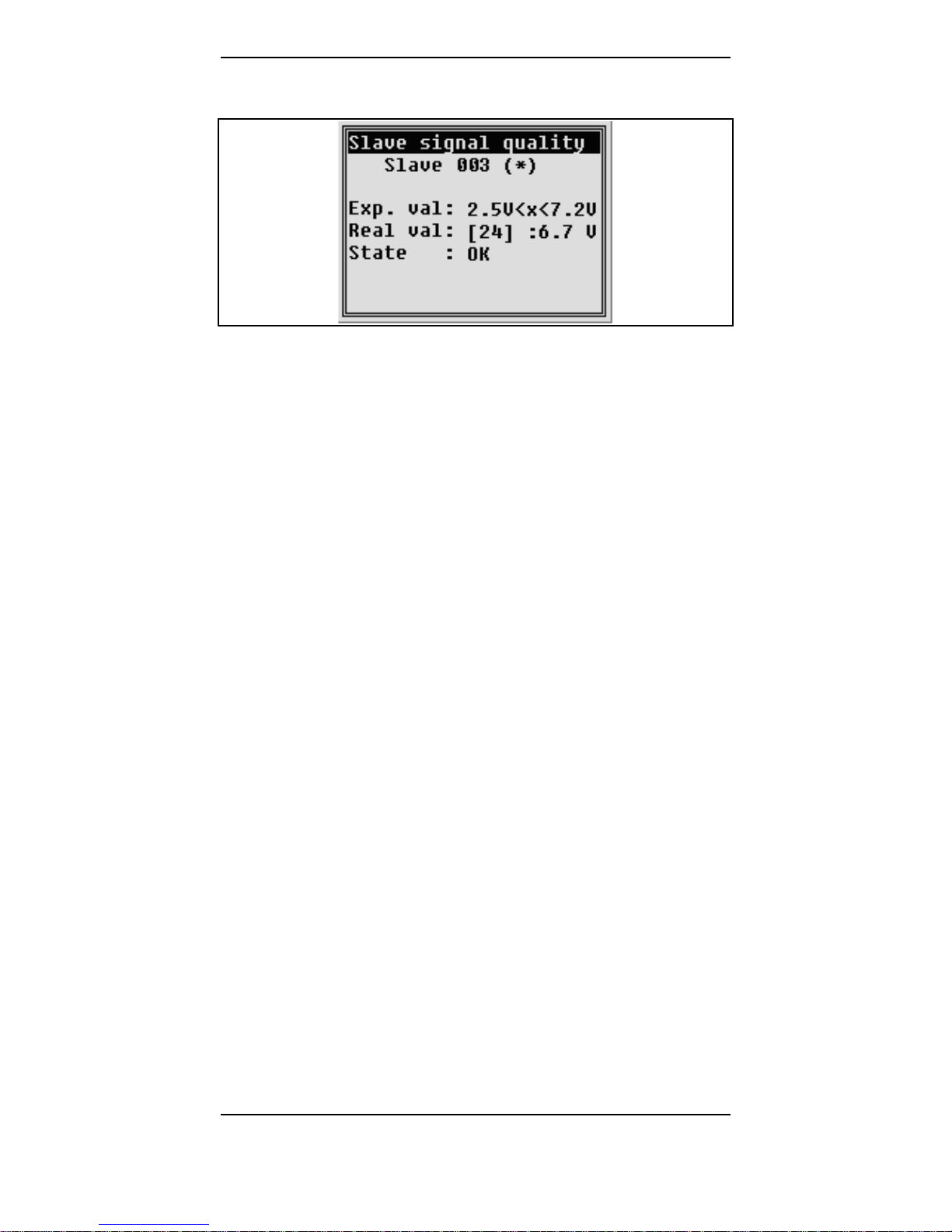
5.2.1.7 Slave signal quality
Figure 13: Screen ‘Slave signal quality’
With the Slave signal quality, the signal level of the addressed
DP Slave is measured. This should be with an impeccable unit
and correctly terminated bus and a cable length of 1 m from
the measuring point to the Slave at approx. 6.3 Volt. Per
100 m more cable between NetTEST II and the device to be
scanned, the level reduces by approx. 0.2 Volt.
U < 2.5 V: Weak level or no longer detectable.
2.5-7.2V: Levelisok.
U > 7.2 V: If the indicated level is >7.2 Volt, this is an
indication for a faulty power supply of the
Slaves or for reflections at the bus.
 Loading...