

Page 1
PH T- SER IE S PANHE A D
OPERATING INSTRUCTIONS
Thank you for making Induro your choice for
professional photographic gear. Your Induro gear
is manufactured to provide years of dependable
service. In order to obtain optimum satisfaction
and performance we suggest that you carefully
read these instructions and provide them to
anyone who may also use your Induro gear.
Speci fications an d design are subje ct to change witho ut notice.
All trad enames, log os, and brand ref erences are the re spectiv e trademark s of their owners .
INDURO Camera Suppor t Gear | 75 Virginia Road, Nor th White Plains, NY 1060 3 | T 914-347-3300 | F 914-347-3309 | info@i ndurogear.com | indurogear.com
Page 2
SETUP
Head Mounting
Instal l by screwing the head clock wise onto the
3/8" Mounting Threa d of the Top Plate of the
Tripod or Monop od. Once it is hand tight, secure
by fully tightening the Head Lo cking Screw(s) (on
selec t models) from below..
OPERATION
Three -way positioning of camera and lens
movement is directly controllable on the
PHT-Seri es Panheads. Two comfortable foldable
Handles provide both movement and locking of
front to rear Tilt, and side to side Tilt. Plus,
a separa te Locking Knob permit s the entire
Head assembly to move freely within a 360°
rotational adjustment.
Quick Release Plate
The PHT-Ser ies Panheads incorporate a Quick
Release Plate system. It offers a quick method of
mounting or releasing a Cam era or Equipment
from the Hea d. It’s import ant that the correct
Quick Release Plate be used along with the
proper mounting screw (1/4–20 is included as
the stand ard size but spar e 1/4–20 and 3/8 pl ates
are avail able as accessor ies). Extra Plates are
recommended as you can screw one to each
Camer a or Lens for even gre ater convenience
when rapidly mounting and dismounting gear.
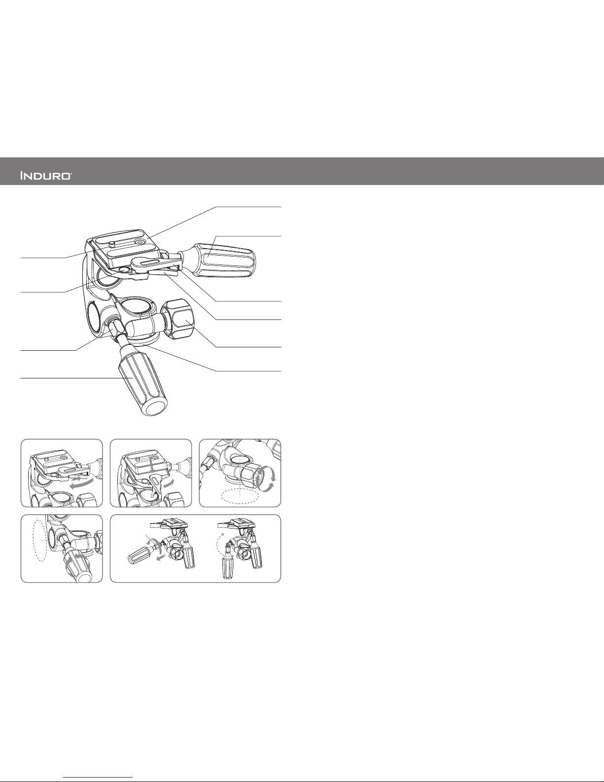
Quick Release Lockin g Lever (FIG URES 1 & 2)
When use d properly, the patented Dual Lock
Quick Release system offers tw o levels of
security for your gear. To remove the Quick
Release Plate, squee ze both the Plate Locking
Lever and the Securit y Lockin g Lever and pul l
the larger Locking Lever out. The Quick Release
Plate will disengag e allowing it to be removed.
To reconnect the Quick Releas e Plate, insert the
angled part of the Plate into the groove on the
opposite side of the Lockin g Levers and press
down flat. The Lockin g Levers will automatically
engage the lo cking system and will return to
the safet y lock posi tion. Pres s the Plate Lo cking
Lever in firmly to secure.
Pan Control (FIGURE 3)
Horizontal rotation or Panning can be easily
accompl ished by first loosening the Pan Lock
and then rotating Head on Platform. Once in
positio n tighten the Pan Lock securely.
NOTE: Do not ov er tighten the Pan Lock as this
could dama ge the locking me chanism.
1
2
360°
3
Locking Collar Nut
54
Locking Collar Nut
Tilt Control (FIGURE 4)
Front to Rear Angle or Tilt adjus tments can be
easily acco mplished by first loosening the Fro nt
to Rear Tilt Control Handle (be sure to hold on
firmly to bal ance weight of the camer a). Position
as required and then tighten Handle securely.
The same Co ntrol and Lock are available on
the other axis for Side to Side Angle or Tilt
adjustments by using the Side to Side Tilt Control
Handle. The Bubble Level can be viewed while
making adjustments.
NOTE: Do not ov er tighten the Tilt Control Locks
as this could damage the locking mechanism.
FOR ADDITIONAL CONTROL : Depending on
your requirements yo u may find it convenient
to reorie nt the camera or lens 90° on the Quick
Release Plate and remount so that the Tilt
Controls give you dif ferent positioning suppor t.
Folding Tilt Control Handles (FIGURE 5)
Both Tilt Control Handles can easily fol d down
along the sides of the PHT Head to make packing
and transport much more convenient. To prepare
for transport (without a camer a mounted), firmly
hold the Handle and rotate the Loc king Collar Nut
counter- clockwise until you can slide it ba ck on
the shaft exposing the joint and all owing it to bend.
Revers e the procedur e to secure the Handle for
normal operation.
USER NOTICE
c Do not excee d the maxim um specifi ed load
capac ity (see specific ations on the package l abel
or visit w ww.InduroG ear.com).
c Alw ays ensure that all Panh ead locks are tightly
engage d before mou nting any gear.
c Alw ays clean and dry any Panh ead after it has been
expos ed to wet, dust y, sandy or sa lty conditions.
Your Panhea d is not recomm ended for use in salt
water. If requir ed, clean Panhead usi ng a mild soap
soluti on applied with a soft clo th, rinse with fre sh
water and dr y with soft towel . Remove any dus t,
dirt or san d from all loc ks and all moving par ts.
c Do not leav e any Panhe ad in the sun for prolonged
perio ds and avoid high temper ature exposure.
c Avoid le aving any Tripod or Monopo d unatte nded
in areas whe re people could trip ov er the gear and
get hurt .
c Remov e camer a, lens, and all gear from any
Tripod or Monop od when transporting.
c For your safety, don’t let your Induro gear come in
contac t with any ele ctrical powe r source.
Quick Release Plate
Side to Side
Tilt Control/Lock Handle
Plate Locking Lever
Pan Control/Lock Knob
Base
Camera Screw
Front/Rear
Tilt Control/Lock Handle
Security Locking Lever
Bubble Level
 Loading...