

Page 1
OPERATION (FIGURE 4)
The GH-Series Gimbal Heads are
professional devices and once adjusted for
typical operation only require two controls.
Slightly loosen both the Tilt Knob and Pan
Knob. Then aim the camera at the subject
and tighten both Knobs to lock.
If you’re photographing and following action,
you may keep both Knobs loose and take
advantage of the stability offered by the
Gimbal Head. Lock the Knobs when you
are finished or are not firmly holding the
Camera/Lens.
FOR OPT IMUM RESULTS: Adjust the balance
and Camera/Lens positioning with the weight
capacity, temperature and conditions under
which the Gimbal Head will be used.
NOTE: Do not over tighten any Locking
Knobs or try to move the Camera/ Lens once
tightened as this could damage the Gimbal
Head locking mechanism.
USER NOTICE
c Do not exceed the maximum specified load
capacity (see specifications on the package
label or visit www.Induro.com).
c Always ensure that all Ballhead locks are
tightly engaged before mounting any gear.
c Do not use any Ballhead below
temperatures of −4°F or above +158°F
(−20°C / +70°C).
c Always clean and dry any Ballhead after
it has been exposed to wet, dusty, sandy
or salty conditions. Your Ballhead is not
recommended for use in salt water. If
required, clean Ballhead using a mild soap
solution applied with a soft cloth, rinse
with fresh water and dry with soft towel.
Remove any dust, dir t or sand from all
locks and all moving parts.
c Do not leave any Ballhead in the sun
for prolonged periods and avoid high
temperature exposure.
c Avoid leaving any Tripod or Monopod
unattended in areas where people could
trip over the gear and get hur t.
c Remove camera, lens, and all gear from
any Tripod or Monopod when transporting.
c For your safety, don’t let your Induro
gear come in contact with any elec trical
power source.
GH-SERIES GIMB AL HE AD
OPERATING INSTRUCTIONS
Thank you for making Induro your choice for
professional photographic gear. Your Induro gear
is manufactured to provide years of dependable
service. In order to obtain optimum satisfaction
and performance we suggest that you carefully
read these instructions and provide them to
anyone who may also use your Induro gear.
Specifications and design are subject to ch ange wi thout notice.
All tradena mes, logos, and bran d r efere nces ar e the respective tradema rks of their owners.
INDURO Camera Support Gear | 75 Virginia Road, North White Plains, NY 10603 | T 914-347-3300 | F 914-347-3309 | info@indurogear.com | indurogear.com
Page 2
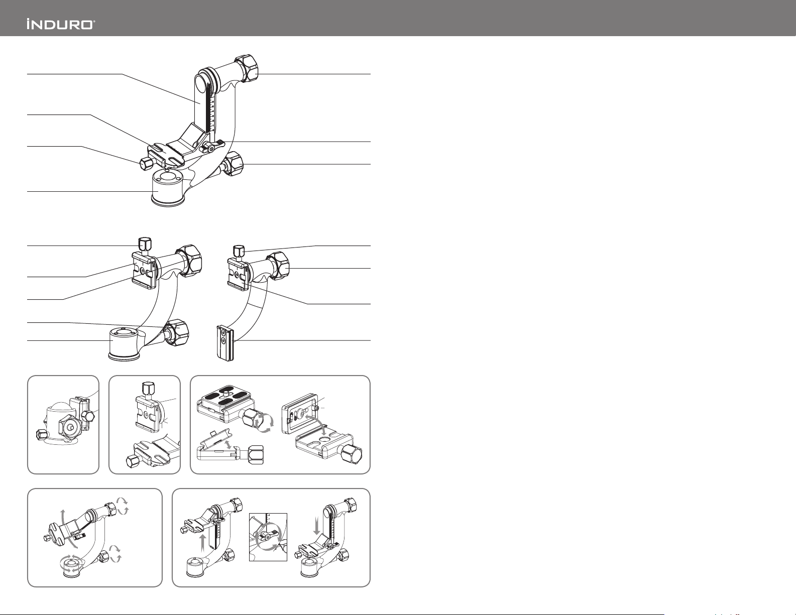
Ballhead not included
Stop Screws (2)
Mounting Screw
Unlock
Lock
Unlock
Lock
Lock
Unlock
Vertical Adjustment Rail
Quick Release
Mount Platform
Quick Release
Locking Knob
Base
Quick Release
GH-Type 1 GH-Type A
Locking Knob
Quick Release
Mount Platform
Tilt Knob
Pan Knob
Base
1 2 3
Type A
Type 1
Type 2
4 5
GH-Type 2
Tilt Knob
Platform Lock Knob
Pan Lock
Quick Release
Locking Knob
Tilt Knob
Quick Release
Mount Platform
Quick Release Plate
INTRODUCTION
Your Induro GH-Series Gimbal Head is a precision
device which, when properly setup allows almost
effortless pan and tilt movements of most Camera/
Lens systems. These instructions cover the proper
setup and operation of three different Types of
Gimbal Heads and should be read completely prior
to mounting and operating your Gimbal Head.
SETUP
Head Mounting (F IGURE 1)
TYPE A: Fit the Quick Release plate onto the
Universal Arca-Swiss sty le Quick Release Clamp
of a Ball Head rated for heavy duty operation. Select
an Induro model or other high quality brand that
incorporates a secondar y Safety Lock System.
TYPE 1: Install by screwing the head clockwise
onto the 3/8" mounting thread of the top plate of
the Tripod. Once the Base is hand tight, if available,
secure by fully tightening the Head Locking Screw(s)
from below with the included Allen Key.
TYPE 2: The camera Quick Release Mount Platform
must first be attached to the Vertical Adjustment
Rail by loosening the Platform Lock Knob and
sliding the Platform down to the bottom of the Rail.
Tighten the Lock Knob. You will be able to adjust
position later after the camera is mounted. Follow
the Type 1 instructions above to attach the Gimbal
Head to your Tripod.
Universal Quick Release Plate System
The GH-Series Gimbal Heads feature a Univers al
Arca-Swiss style Quick Release Plate system. It
offers a quick method of mounting or releasing a
Camera or Equipment from the Head. It’s impor tant
that the correc t Quick Release Plate be used along
with the proper mounting screw (1/4–20 is included
as the standard size but spare 1/4–20 and 3/8 plates
of various lengths are available as accessories).
The Mounting Screw requires an Allen Key which
is included. Extra Plates are recommended as you
can screw one to each Camera or Lens for even
greater convenience when rapidly mounting and
dismounting gear. And because of compatibility with
the Universal Arca-Swiss style system, most plates
and special brackets from other manufacturers can
be used as well.
Quick Release Mount Platform (FIGU RE 2)
All three Gimbal Head models feature a center line
on the Quick Release Mount Platform for reference
positioning of the Quick Release Pl ate. In addition,
the longer Type 2 Quick Release Platform allows
for greater flexibilit y in providing camera balance,
and includes full scale index marks for more
precise repositioning.
Quick Release Lock (FIG URE 3)
When used properly, the Quick Release Lock offer s
two levels of security for your gear. To remove the
Quick Release Plate, firmly hold the Camera/Lens
and turn the Quick Release Locking Knob counterclock wise. A partial opening of the clamping
mechanism allows the Quick Release Plate to slide
on the Mounting Platform for proper balance and
positioning. Two Stop Screws (removable) on the
bottom of the Quick Release Plate provide this first
level of security. An additional counter-clockwise
turn of the Quick Release Locking Knob opens the
clamp fully so that the Quick Release Plate can be
tilted out to be removed. Reverse the process once
again firmly holding the Camera/Lens and tighten
the Quick Release Locking Knob to secure the Quick
Release Plate.
Gimbal Head Tilt Control (FIGUR E 4)
When fully adjusted, the later al positioning of
a Camera/Lens on a Gimbal Head should allow
neutr al balance which means that most front and
rear tilt movements will stay fixed even with the
Tilt Knob unlocked. Best positioning may require
the purchase of an accessory ex tra-long plate.
Type 2 Gimbal Heads offer the additional feature
of an indexed vertical adjustment to permit better
alignment of the Lens Axis with the Tilt Axis.
Setting System Balance (FIGU RES 4 & 5)
While holding the Camera/Lens, rotate the Tilt
Knob counter-clockwise to loosen the Tilt Pivot.
Allow the Arm to swing gently to determine whether
the natural movement of the weighted mechanism
is to tilt up or down. If the lens is tilting down then
while still holding the Camera/Lens partially
loosen the Quick Release Locking Knob and slide
the mounted Camera/Lens to the rear until neutral
balance is achieved. Turn the Quick Release Locking
Knob clockwise to secure.
Type 2 Gimbal Heads offer the same setting for
balance, however this adjustment should be made
after the Lens Axis is positioned approximately
in-line with the Gimbal Tilt Axis. The vertical
adjustment can accomplished by turning the
Plat form Lock Knob counter-clockwise and sliding
the entire Platform up to position. Once you have
found the neutral balance point tighten the Platform
Lock Knob clockwise to secure.
(CONTINUE D ON BACK PAG E)
 Loading...