

Page 1
BHS-SERIES BALLHEAD
BHD –SERIES B ALL HEAD
OpER AtIng InS tRuc t IOnS
Thank you for making Induro your choice for
professional photographic gear. Your Induro gear
is manufactured to provide years of dependable
service. In order to obtain optimum satisfaction
and performance we suggest that you carefully
read these instructions and provide them to
anyone who may also use your Induro gear.
OPERATING INSTRUCTIONS
Thank you for making Induro your choice for
professional photographic gear. Your Induro gear
is manufactured to provide years of dependable
service. In order to obtain optimum satisfaction
and performance we suggest that you carefully
read these instructions and provide them to
anyone who may also use your Induro gear.
Specifications and desi gn are subject to change wi thout notice.
All tradena mes, logos, and brand refer ence s are the respective tr ademarks of their own ers.
INDURO Camera Support Gear | 75 Virginia Road, Nor th White Plains, NY 10603 | T 914-347-3300 | F 914-347-3309 | info@indurogear.com | indurogear.com
Page 2
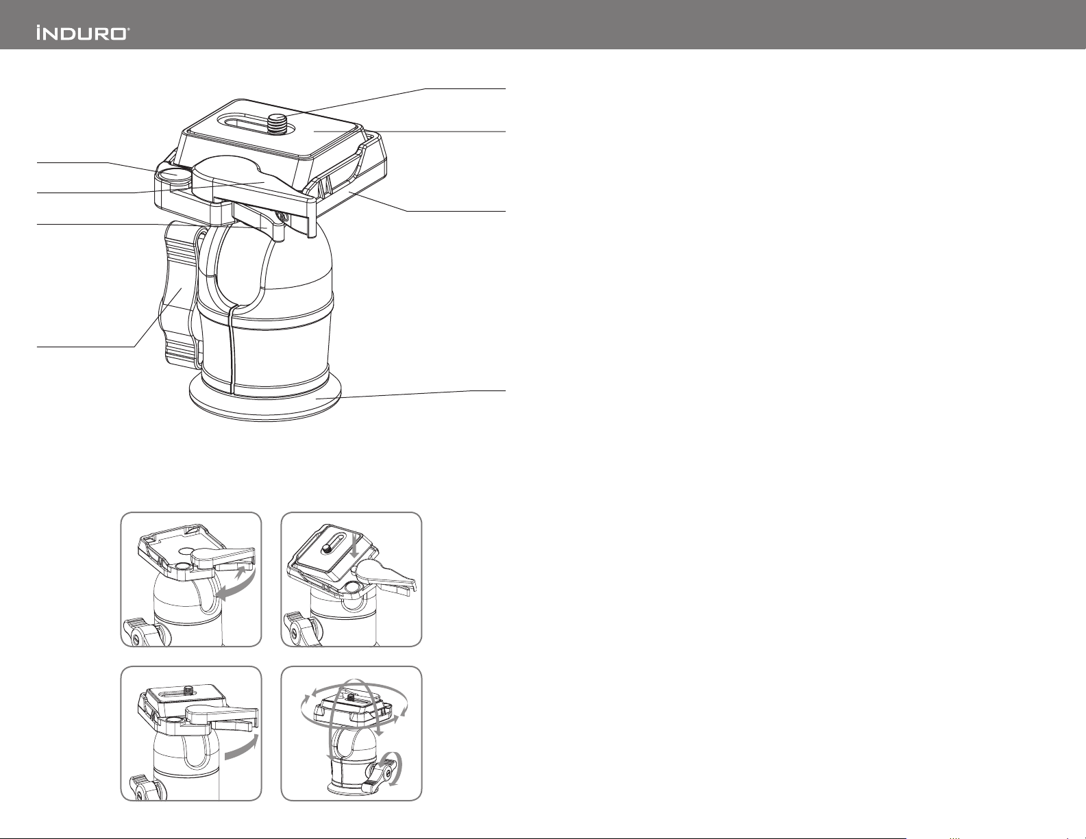
Bubble Level
360°
90°
Plate Locking Lever
Security Locking Lever
Ball Locking Lever
1 2
Camera Screw
Quick Release Plate
Mounting Platform
Base
SETUP
Head Mounting
Install by screwing the head clockwise onto
the 3/8" mounting thread of the top plate of the
Tripod or Monopod. Once it is hand tight,secure
by fully tightening the Head Locking Screw(s)
(on select models) from below.
OPERATION
The single-action Ball Locking Lever controls
all movements of the BHS-Series Ballheads.
When released, the Ballhead and the Mounting
Platform can move freely within a 360° rotational
adjustment. And a U-shaped opening provides
90° angular movement of the Mounting Platform.
Quick Release Plate
The BHS-Series Ballheads incorporate a Quick
Release Plate system. It offers a quick method of
mounting or releasing a Camera or Equipment
from the Head. It’s important that the correct
Quick Release Plate be used along with the
proper mounting screw (a spare 1/4–20 plate
is available as an accessory). Extra Plates are
recommended as you can screw one to each
Camer a or Lens for even greater convenience
when rapidly mounting and dismounting gear.
Quick Release Locking Lever
(FIGU RES 1, 2 & 3)
When used properly, the patented Dual Lock
Quick Release system of fers two levels of
security for your gear. To remove the Quick
Release Plate, squeeze both the Plate Locking
Lever and the Security Locking Lever and pull
the larger Locking Lever out. The Quick Release
Plate will disengage allowing it to be removed.
To reconnect the Quick Release Plate, insert the
angled part of the Plate into the groove on the
opposite side of the Locking Levers and press
down flat. The Locking Levers will automatically
engage the locking system and will return to
the safety lock position. Press the Plate Locking
Lever in firmly to secure.
USER NOTICE
c Do not exceed the maximum specified load
capacity (see specifications on the package
label or visit InduroGear.com).
c Always ensure that all Ballhead locks are
tightly engaged before mounting any gear.
c Always clean and dry any ballhead after it has
been exposed to wet, dusty, sandy or salt y
conditions. Your Ballhead is not recommended
for use in salt water. If required, clean Ballhead
using a mild soap solution applied with a sof t
cloth, rinse with fresh water and dry with soft
towel. Remove any dust, dir t or sand from all
locks and all moving parts.
c Do not leave any Ballhead in the sun for
prolonged periods and avoid high temperature
exposure.
c Avoid leaving any Tripod or Monopod
unattended in areas where people could trip
over the gear and get hurt.
c Remove camera, lens, and all gear from any
Tripod or Monopod when transpor ting.
c For your safety, don’t let your Induro gear come
in contact with any electrical power source.
3
4
The single-action Ball Locking Lever controls all
movements of the BHS-Series Ballheads.
NOTE: Do not over tighten the Locking Lever as this
could damage the Ballhead locking mechanism.
Ball Locking Lever (FIG URE 4)
 Loading...