

Page 1
USER NOTICE
c Do not exceed the maximum specified load
capacity [see specifications on the package label
or visit www.indurogear.com)
c Always ensure that leg and head locks are tightly
engaged before mounting a camera on the tripod
c Always clean and dry the tripod after it has been
exposed to wet, dusty, sandy or salt y conditions.
Your tripod is not recommended for use in salt
water. If required clean tripod using a mild soap
solution applied with a soft cloth and follow by
wiping down with fresh water. Remove any dust,
dirt or sand from all leg locks, leg lock levers, leg
sections and all moving parts.
c Do not leave the product in the sun for prolonged
periods and avoid high temperature exposure
c Avoid leaving the tripod unattended in areas where
people could trip over the tripod and get hur t
c Remove camera, lens, and all gear from the tripod
when transporting the tripod
c For your safety, don’t let your Induro tripod come
in contact with any electr ical power source
ADVENTURE AK-SERIES TRIPOD KIT
OPERATING INSTRUCTIONS
Thank you for making Induro your choice for
professional photographic gear. Your Induro gear
is manufactured to provide years of dependable
service. In order to obtain optimum satisfaction
and performance we suggest that you carefully
read these instructions and provide them to
anyone who may also use your Induro gear.
Specification s and design are subject to change without not ice.
INDURO Camera Suppor t Gear | 75 Virginia Road, North White Plains, NY 10603 | T 914-347-3300 | F 914-347-3309 | info@indurogear.com | indurogear.com
Page 2
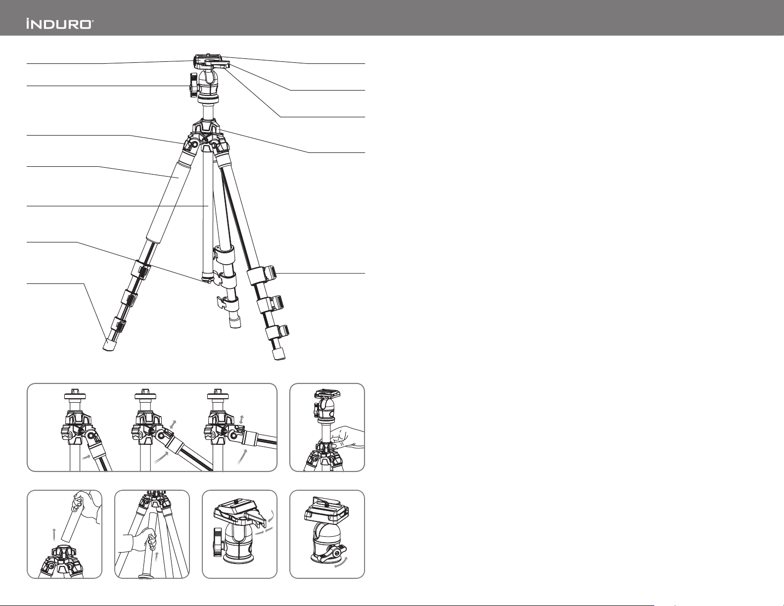
Quick Release Plate
Head Locking Lever
Leg Angle Adjustment Lock
Closed Cell Foam Grip
Reversible Grooved
Center Column
Retractable
Weight Hook
Flip-style Leg Lock Lever
All-Terrain Foot
1 2
4
5
AKB model on ly
Camera Screw
Plate Locking Lever
Security Locking Lever
Center Column
Locking Knob
(shown open)
63
AKB model on ly
OPERATION
To use your tripod, swing all three legs out until they
stop at the fir st locking point. While holding upper
Leg Section, grab flat part of Leg Lock and flip out
to unlock and release tension on Leg Sections. Slide
Leg Sections out to achieve desired length (tripod
height) and then close Leg Locks firmly to secure
each Leg Section in place. Ensure that the tripod is
firmly resting on a level surface. Tighten Mounting
Screw on Quick Release Pl ate into the threaded
tripod mount on the base of your camer a or lens and
then snap-in securely on the Tripod Head. Always
press Plate Locking Lever in fir mly and engage
any safety locks on the Tripod Head to prevent any
accidental dismounting. While holding the camera
loosen the Head Locking Lever and orient camer a
to desired shooting position and then tighten Head
Locking Lever.
FOR BES T RESULTS: Do not raise the tr ipod taller
than necessary and extend largest diameter
Leg Sections first. Only extend Center Column if
required to reach maximum height or to fine tune
vertical position.
NOTE: Never carry your tripod with camera
gear attached.
Leg Angle Adjustment (FIG URE 1)
To accommodate uneven terrain, awkward shooting
situations or for low angle shooting, your Induro
tripod includes a 3-position leg angle adjustment
sliding lock. Each leg can be independently adjusted
by pulling the sliding leg angle lock out and
selecting one of the three step positions (24, 55 or 80
degrees). Ensure that the leg angle lock is securely
pushed back into the lock position af ter you have
selected the desired leg angle.
Leg Section Adjustment ( MAIN FIGUR E)
Each leg section can be independently adjusted to
the desired length by pulling open the Flip-st yle Leg
Lock Levers. Once unlocked the leg is free to slide
in or out to adjust to the desired length. Close the
Flip-style lever securely to clamp and lock the leg.
Repeat this step for each leg and each section until
the tripod is set to the desired height.
NOTE: To prevent any accidental damage to your
gear, always remove any mounted equipment
(camera, etc) from the tripod before adjusting the
leg sec tions.
Raising and Lowering the Center Column
(FIGU RE 2)
To raise or lower the center column, turn the center
column locking knob counter-clock wise and slide
the column to the desired position. While holding
the column in position, turn the column locking knob
clock wise to secure the column in place. Don’t over
tighten the center column lock, as this could damage
the threads.
NOTE: Take special care when raising or lower ing
the center column, if a camera or equipment is
mounted on the tripod. Never loosen the center
column lock without holding the center column.
Failure to follow these instructions could result in
damaged equipment.
Reversible Center Column (F IGURES 3 & 4)
Your tripod offers the ability to reverse the Center
Column for close-up photogr aphy, copy work and
for difficult to reach objects. To reverse the Center
Column, unscrew the Weight Hook located on the
bottom of the Center Column. Loosen the Center
Column Locking Knob and pull the Center Column
out. Insert the Center Column with the mounting
plate upside down and retighten the Center Column
Locking Knob securely. The Center Column has a
grooved slot to prevent unwanted rotation. Be sure
to line-up the groove with the key before inserting
the column back into the main casting.
NOTE: Do not reverse the Center Column when a
camera or equipment is mounted.
TRIPOD HEAD OPERATION
AKP ADVENTURE TRIPOD KIT – Please refer to the
separate PHT 3-Way Panhead operating instruction.
AKB ADVENTURE TRIPOD KIT – the follow ing
instr uctions apply to the Ballhead operation.
Quick Release Plate
The Adventure Series Ballheads incorporate a Quick
Release Plate system. It offers a quick method of
attaching and removing a camera or equipment
from the tripod head. Extra plates are available
separately so you can screw one to each camera
or lens for even greater convenience when rapidly
mounting and dismounting gear from your tripod.
Quick Release Locking Lever (FIGURE 5)
A patented dual lock quick release system when
used properly offers two level s of security for your
gear. To remove the Quick Release Plate, squeeze
both the Security Locking Lever and the Plate
Locking Lever, and pull the larger Plate Locking
Lever out. The Quick Release Plate will disengage
so it can be removed. To reconnect the Quick
Release Plate, insert the angled par t of the plate
into the groove on the opposite side of the Locking
Lever and press down flat. The locking levers will
automatically engage the locking system and the
locking levers will return to the safet y lock position.
Press the Plate Locking Lever in firmly to secure.
Head Locking Lever (F IGURE 6)
The single action ball-locking lever controls all
movements of the ballhead. When released the head
and the camera mounting platform can move freely
providing 90-degree angular and 360-degrees
rotational adjustment on the tripod pl atform.
 Loading...