

Page 1
C T– SER IES & AT–SERIES T R IPODS
OPER AT Ing InST RuC TIOnS
INDURO Camera Support Gea r | 8 We stchester Plaza, Elms ford, NY 10523 | T 914-347-3300 | F 914-347-3 309 | info@indurogear.com | indurogear.com
Thank you for making Induro your choice for
professional photographic gear. Your Induro gear
is manufactured to provide years of dependable
service. In order to obtain optimum satisfaction
and performance we suggest that you carefully
read these instructions and provide them to
anyone who may also use your Induro gear.
Interchangeable Spiked and Rubber Feet
(selec t models)
(MAIN F IGURE)
Most Induro tripods include interchangeable
Stainless Steel Spiked or Rubber Feet.
They pr ovide the rig ht contact dep ending
on the surface or terrain that the tripod
will be used in. To remove the Rubber Feet
simply un screw each Rub ber Foot counte rclock wise and repl ace with the pr ovided
Spiked Fe et. Tighten the S piked Feet usin g
the inclu ded Wrench.
Accessory Short Column (FIG URE 9)
An acce ssory Sho rt Column is av ailable to
replace the Standard Center Column for
performance operation and and low level
camera positioning. To install, rst remove
Tripod Hea d, Locking Nu t, Top Plate, Mount ing
Screw and Weight Hook. Loosen the Center
Column L ocking Knob a nd pull the Cente r
Column out. Insert the new Short Column in
place, tighten Center Column Locking Knob
and reassemble Top Plate mounting parts,
Tripod Head, and Weight Hook.
Multi-Function Spider Casting
The heavy-duty, extra-wide Magnesium Alloy
cross -braced cent er casting wa s designed
to provide the greatest core stability for
your Ind uro Tripod. In addi tion, it inclu des
an integral Bubble Level, removable
Carr ying Strap L oop and a dual thr eaded
Acces sory Mount .
USER NOTICE
Do not exce ed the maximum s pecied lo ad c
capacity (see specications on the package
label o r visit ww w.indurog ear.com).
Always ensure that Leg and Head Locks c
are tight ly engaged bef ore mounting a ny
gear on yo ur Tripod.
Do not use any Tripod below temperatures c
of −4°F or ab ove +158°F (−20° C / +70°C ).
Always clean and dry any Tripod after it c
has been exposed to wet, dusty, sandy
or salty conditions. Your Tripod is not
recommended for use in salt water. If
required, clean tripod using a mild soap
solution applied with a soft cloth, rinse
with fresh water and dry with soft towel.
Remove any dust, dirt or sand from all Leg
Locks , Leg Secti ons and all mov ing parts .
Do not leave any Tripod in the sun c
for prolonged periods and avoid high
temperature exposure.
Avoid leaving any Tripod or Monopod c
unatte nded in areas w here people c ould
trip ov er the gear and get h urt.
Remove c amera, lens , and all gear fr om c
any trip od when tran sporting .
For your s afety, don’t let y our Induro c
gear come in contact with any electrical
power source.
Speci fication s and design a re subjec t to change wi thout noti ce.
Page 2
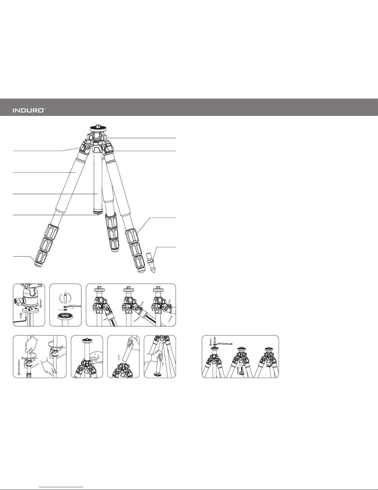
SETUP
Head Mou nting (FIGUR ES 1 & 2)
If your Tripod did not come with a Head, select one
of the ne Induro Tripod Heads that match your size
Tripod an d install b y screwi ng the Head cl ockwis e onto
the 3/8" Mounting Thread of the Top Plate. Once it is
hand tight, secure by fully tightening the Head Locking
Screw (s) from belo w with the incl uded Allen Ke y.
Most Heads have a 3/8" base mount so your Induro
Tripod is shipped with the 3/8 Mounting Thread
exposed, but if the Head you choose uses a 1/4–20
you can attach it by simply reversing the Mounting
Screw. To do th is turn the Lock ing Nut counter clockwise (using the supplied Wrench) until it
becomes loose, and unscrew the Mounting Screw
until it can be completely removed. Reverse the
Screw, so that the threads are in position and screw
it back into place, secure with the Locking Nut using
the Wren ch.
NOTE: Allow enough of the screw threads to be
available for maximum security when the Tripod
Head is mounted onto the Tripod. It’s recommended
that at least 5 to 6 threads be exposed before locking
the Mount ing Screw in pl ace.
OPERATION
Before using your Tripod, adjust each Leg Section to
the desi red height and L eg Angle Set ting.
Make sure that the Tripod is rmly resting on a level
surface and mount your camera securely on the
Tripod Head. Always engage any safety locks on the
Tripod Hea d to prevent any ac cidental dism ounting.
FOR BEST RESULTS: Do not raise the Tripod higher
than necessary and extend the largest diameter
Leg Sections rst. Only extend the Center Column
if required to reach maximum height or to ne-tune
the ver tical positi on.
FOR EXTRA STABILIT Y: Carefully hang your camera
bag or oth er weight on the Ret ractable S pringLoaded Weight Hook at the bottom of the Center
Column.
NOTE: Never carry your Tripod with camera
gear at tached.
Leg Ang le Adjustmen t (FIGURE 3)
To accommodate uneven terrain, awkward shooting
situations or for low angle shooting, your Induro
Tripod includes a 3-position Leg Angle Adjustment
Slidin g Lock. Each L eg can be adjus ted by pulling th e
Leg Angle Lock out and selecting one of the three
positions. Please make sure that the Leg Angle Lock
is securely pushed back into the lock position after
you have s elected the d esired Leg A ngle.
Leg Sec tion Adjust ment (FIGURE S 4 & 5)
Each Leg section can be adjusted to the desired
length by turning the leg lock grip 1/2 turn (180°)
clockwise until the Leg is free to slide in or out. Once
the desired length is achieved, turn the Leg Lock Grip
counter-clockwise until the Leg Section is securely
locked. Repeat this step for each Leg and each
Sect ion until the Tripod i s set to the desir ed height.
NOTE: To pre vent any accide ntal damage to y our gear,
always remove any mounted equipment (camera, etc.)
from the Tripod before adjusting the Leg Sections.
Raising and Lowering the Center Column
(FIGUR E 6)
To raise or lower the Center Column, turn the Center
Column Locking Knob clockwise and set the Column
to the desired position. While holding the Column
in position, turn the Center Column Locking Knob
counter-clockwise to secure the Column in place.
Don’t over-tighten the Center Column Lock, as this
could da mage the thread s.
NOTE: Take special care when raising or lowering
the Center Column, if a camera or equipment is
mounted on the Tripod. Never loosen the Center
Column Locking Knob without holding the Center
Column. Failure to follow these instructions could
result i n damaged equi pment.
Reversi ble Center Col umn (FIGURE S 7 & 8)
Your Tripod has the ability to reverse the Center
Column for close-up photography, copy work and for
difc ult to reach obj ects.
To reverse the Center Column, unscrew the
Retractable Weight Hook located on the bottom
of the Center Column. Loosen the Center Column
Locking Knob and pull the Center Column out.
Insert the Center Column through the bottom with
the Mounting Plate upside-down and reti ghten the
Center Column Lock ing Knob securely. The Center
Column has an anti-twist groove, be sure to line-up
the groove with the key before inserting the Column
back into t he Main Castin g.
NOTE: Do not reverse the Center Column when a
camer a or equipment i s mounted.
31
Locking
Nut
1/4-20 + 3/8
Mounting Screw
Wrench
2
Unlock Lock
4 5 6
7
8
Center Column
Locking Knob
Spider Casting
Retractable
Weight Hook
Leg Lock Grip
Closed Cell Foam Grip
Leg Angle Adjustment Lock
Rubber Foot
Reversible Grooved
Center Column
Interchangeable
Spiked Foot
(on sele ct models)
9
 Loading...