

Page 1
ADVENT URE AK-SERIES TRIPOD KIT
OPERATING INSTRUCTIONS
Thank you for making Induro your choice for
professional photographic gear. Your Induro gear
is manufactured to provide years of dependable
service. In order to obtain optimum satisfaction
and performance we suggest that you carefully
read these instructions and provide them to
anyone who may also use your Induro gear.
USER NOTICE
c Do not exceed the ma ximum specified lo ad
capac ity [see specific ations on the packag e label
or visit w ww.induro gear.com)
c Alway s ensure th at leg and head lo cks are tightly
engage d before mo unting a camera on the trip od
c Alway s clean and dr y the tripod after it has be en
expos ed to wet, dust y, sandy or salty conditions .
Your tripod is not re commended for use in salt
water. If requir ed clean tripod using a mild soap
soluti on applied with a soft clo th and follow by
wiping do wn with fresh water. Remov e any dust,
dirt or san d from all leg lo cks, leg lock lever s, leg
secti ons and all moving par ts.
c Do not leave the pr oduct in the sun for prolon ged
perio ds and avoid high temper ature exposure
c Avoid leav ing the tripod unat tended in areas where
people co uld trip over the tripod an d get hurt
c Remove camera, len s, and all gear from the tripo d
when tra nsporting the tr ipod
c For your safe ty, don’t let your Induro trip od come
in contac t with any ele ctrical powe r source
Speci fications an d design are subje ct to change witho ut notice.
INDURO Camera Suppor t Gear | 75 Virginia Road, Nor th White Plains, NY 1060 3 | T 914-347-3300 | F 914-347-3309 | info@indurogear.com | indurogear.com
Page 2
AKB mo del only
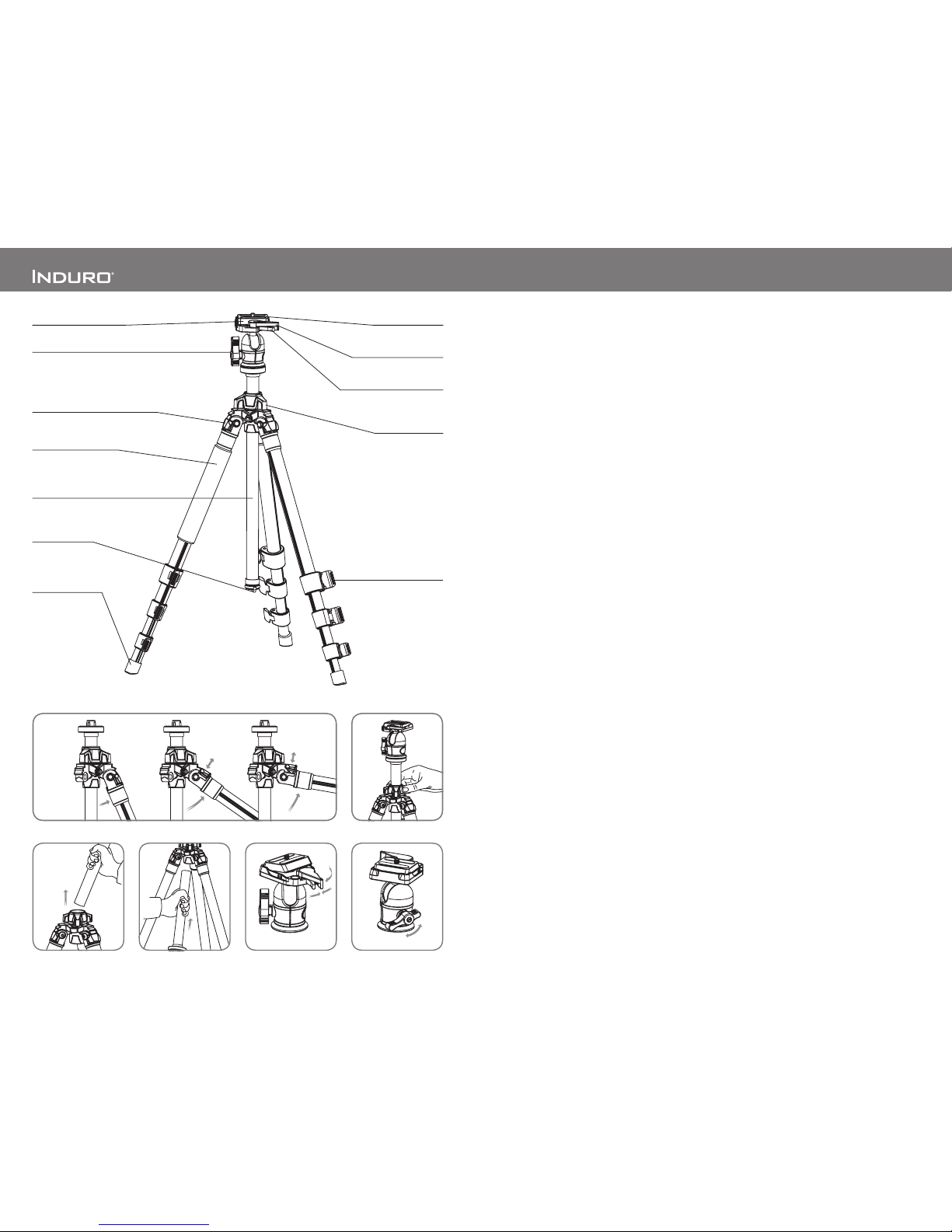
OPERATION
To use your tripo d, swing all three le gs out until they
stop at the fir st locking point. W hile holding uppe r
Leg Sec tion, grab flat part of Leg Lock and flip out
to unlock and r elease tension on Le g Sections. Sli de
Leg Sec tions out to achieve de sired length (tripod
height) an d then clos e Leg Locks firmly to se cure
each Leg Se ction in place. En sure that the tripod is
firmly re sting on a level surf ace. Tighten Moun ting
Screw on Qu ick Release Plate into the thread ed
tripo d mount on the ba se of your camera or len s and
then snap -in securely on the Tripo d Head. Always
press P late Locking Lev er in firmly and engage
any safet y locks on the Tripod Head to prevent any
acciden tal dismounting . While ho lding the camera
loosen th e Head Loc king Lever and ori ent camera
to desire d shooti ng position and then tighten Head
Lockin g Lever.
FOR BES T RESULTS: Do not raise th e tripo d talle r
than nece ssary and ex tend largest dia meter
Leg Sec tions first. Only extend Cent er Column if
requir ed to reach maximum hei ght or to fine tune
vertical position.
NOTE: Ne ver carry your tr ipod with camer a
gear att ached.
Leg Angl e Adjus tment (FIGURE 1)
To accommodate uneven ter rain, awkwa rd shooting
situati ons or for low angle shoo ting, your Induro
tripo d includ es a 3-pos ition leg angle adju stment
slidin g lock. Ea ch leg can be independ ently adjusted
by pullin g the sliding leg angle lo ck out and
selec ting one of the three step po sitions (24, 55 or 8 0
degree s). Ensure that the leg an gle lock is securely
pushed b ack into the lock position after you ha ve
selec ted the desired leg an gle.
Leg Sec tion Adjustmen t (MAIN FIGUR E)
Each leg se ction can be indep endently adjusted to
the desir ed length by pullin g open the Fl ip-style Le g
Lock Lev ers. Once unlocke d the leg is fre e to slide
in or out to adjus t to the desir ed length. Close th e
Flip- style lever se curely to clamp and lo ck the leg.
Repeat thi s step for each leg and each se ction until
the tripod is set to the desir ed height.
NOTE: To preve nt any accidental dam age to your
gear, always remove any mou nted equipment
(camer a, etc) from the tripo d befor e adjust ing the
leg sec tions.
Raisin g and Lower ing the Center Colu mn
(FIGUR E 2)
To raise or lowe r the center co lumn, turn the center
column lo cking knob counter -clockwis e and slide
the column to th e desired positio n. While holding
the column in position, turn the colum n lockin g knob
clock wise to secure the column in place . Don’t over
tighten the center column lo ck, as this could dam age
the threa ds.
NOTE: Take spec ial care when rais ing or lowering
the center co lumn, if a camera or equi pment is
mounted on th e tripo d. Never loosen the ce nter
column lo ck without holdin g the center co lumn.
Failure to fol low these instr uctions could re sult in
damaged equipment.
Reversi ble Center Column (FIGURE S 3 & 4)
Your tripo d offer s the ability to reve rse the Center
Column fo r close -up photograp hy, copy wor k and
for diffi cult to reach objec ts. To reverse the Cent er
Column , unscr ew the Weight Hook loca ted on the
bottom of th e Center Column. Loo sen the Center
Column Lo cking Knob and pul l the Center Column
out. Insert the Center Column wi th the mounting
plate ups ide down and retight en the Center Column
Lockin g Knob securely. Th e Center Co lumn has a
groove d slot to prevent unwa nted rotation. Be su re
to line-u p the groo ve with the key before ins erting
the column b ack into the main castin g.
NOTE: Do no t rever se the Center Column w hen a
camer a or equipment is mounte d.
TRIPOD HEAD OPERATION
AKP AD VENTURE TRIPOD KIT – Ple ase refer to the
separ ate PHT 3-Way Panhe ad operating ins truction.
AKB AD VENTURE TRIPOD KIT – the fo llowing
instr uctions apply to the B allhead opera tion.
Quick Rele ase Plate
The Adv enture Series B allheads incor porate a Quick
Releas e Plate system. It of fers a quick method of
attac hing and removing a ca mera or equipmen t
from the tr ipod head. Ext ra plates are ava ilable
separ ately so you can screw one to each camer a
or lens for even greater con venience when ra pidly
mountin g and dismo unting gear from you r tripo d.
Quick Rele ase Locking Lev er (FIGURE 5)
A patented du al lock quick releas e syst em when
used pro perly offers t wo levels of secu rity for your
gear. To remove the Quic k Releas e Plate , squee ze
both the Se curity Locki ng Lever and the Plate
Lockin g Lever, and pull the large r Plate Lo cking
Lever ou t. The Quick Release P late will diseng age
so it can be removed. To reconn ect the Quick
Releas e Plate, insert th e angled pa rt of the plate
into the groo ve on the opposite side of th e Locki ng
Lever and p ress down flat. T he locking lever s will
automat ically engage the lo cking system an d the
lockin g lever s will ret urn to the safety loc k position.
Press the Plate Loc king Lever in firmly to se cure.
Head Loc king Lever (FIGU RE 6)
The singl e actio n ball-l ocking lever cont rols all
moveme nts of the ballhead . When released the head
and the camera mounti ng platform ca n move fre ely
provi ding 90-degr ee angular and 360 -degrees
rotati onal adjustment on the tripod pl atform.
Quick Release Plate
Center Column
Locking Knob
Retractable
Weight Hook
Flip-style Leg Lock Lever
(shown open)
Camera Screw
Closed Cell Foam Grip
Leg Angle Adjustment Lock
Head Locking Lever
All-Terrain Foot
Reversible Grooved
Center Column
Plate Locking Lever
Security Locking Lever
1 2
63
4
5
AKB mo del only
 Loading...