

Indumicro IMP-A150, IMP-A120, IMP-A170, IMP-A190 User Manual

1
User
Manual
IMP-A120 / A150 / A170 / A190
Industrial Panel PC

Warning!
___________________________________
This equipment generates, uses and can radiate radio frequency ener
gy and if not installed and
used in accordance with the instructions manual may cause interference to radio communications.
It has been tested and found to comply with the limits for a Class A computing device pursuant to
FCC Rules, which are designed to provide reasonable protection against such interference when
operated in a commercial environment. Operation of this equipment in a residential area is likely
to cause interference in which case the user at his own expense will be required to take whatever
measures may be required to correct the interference.
Disclaim
er
This information in this document is subject to change wi
thout notice. In no event shall
Indumicro.com be liable for damages of any kind, whether incidental or consequential,
arising from either the use or misuse of information in this document or in any related
materials.
Electric Shock Hazard – Do not operate the machine with its back cover removed. There are
dangerous high voltages inside.
___________________________________

Table of Contents
Chapter 1: Getting Started
1.1 Specifications…………………………………………………………………………..1
1.2
Dimensions…………………………………………………………………………….2
1.3 Brief Description of the IMP-A1x0. ......................................………………………6
Chapter 2: BIOS Setup
2.1 Operations after POST Scr
e
en..…....……………………..
………………………..7
2.2 Standard CMOS Features..…………………………………………………………..9
2.3 Advanced BIOS Features..………………………………………………………….12
2.4 Advanced Chipset Features.………………………………………………………..15
2.5 Integrated Peripherals……………………………………………………………….19
2.6 Power Management Setup...………….……………………………………………24
2.7 PnP/PCI Configurations...………….……………………………………………….27
2.8 PC Health Status....………….………………………………………………………29
2.9 Load Fail-Safe/Optimized Defaults...………………………………………………30
2.10 Set Administrator/User Passwords.………………………………………………31
2.11 Save & Exit Setup……………….....………………………………………………32
2.12 Exit Without Saving ………………....……………………………………………
32

Specs
IMP-A120T IMP-A150[G]T IMP-A170[G]T
Model
CPU Intel Atom N270 1.6 GHz processor with FSB 533 MHz
Chipset
Intel 945GSE+ Intel ICH7M
System Memor
y 1 x 200-pin DDR2 533 MHz SO-DIMM slot, up to 2 GB
BIOS Award 4 MB SPI BIOS
Display Size
Maximum Colors
Viewing Angle (H/V)
Lumi
nanc
e
(cd/m²)
262K
140˚ /110˚
370
12.1” 800x600 TFT
16.2M
15” 1024x768 TFT
350
140˚/125˚
17” 1280x1024 TFT
16.2M
300
160˚/160˚
19” 1280x1024 TFT
16.2M
300
160˚/160˚
Backlight Lifetime 40,000 Hours
To uc h Sc r ee n Typ e
Analog Resistive on ‘T’ models, GFG on ‘GT’ models
Serial Port
2 x RS-232 Port, 1 x RS-232/422/485 Port
USB Port
LAN 2 x Gigabit LAN
4 x USB 2.0 Port
Display Port
Audio MIC, Line-out
VGA
1 x CF slot (external)
Storage
1 x 320
GB HDD,
Exp
ansi
on Sl
ot
None
Powe
r Su
ppl
y
11~32 VDC
Constructi
on Heavy-duty Steel Ch
assis
Ratin
g
NEMA
4/IP65 certified Front Bezel
Mounting Panel / VESA 75 Mount
Dimensions (WxHxD)
4
10
x 310 x 83
484
x 400 x 84
317
x 243 x 76
439
x 348 x 83
Weight
5.82kg 8.5kg 13.8kg
10kg
Operatin
g Temperatur
e
S
t
orage T
e
mperature
Relativ
e
Hum
idity
V
ibrati
on
Shock
Certificate
10~90% (non-cond
ensi
ng)
5~
17Hz, 0.1” d
oub
le amp
litude
disp
lacem
ent
/ 17~640Hz, 1.5G acceleration peak to peak
10G accelerati
on pe
ak to pea
k (11 millimeters)
Meet CE / FCC Class A
0~50
-20~60
゚C
゚C
1.1 Specifications
Chapter 1: Getting Started
IMP-A190T
IMP-A1x0T User Manual
1
Power consumption
Max. 21W Max. 35W Max. 45W Max. 45W
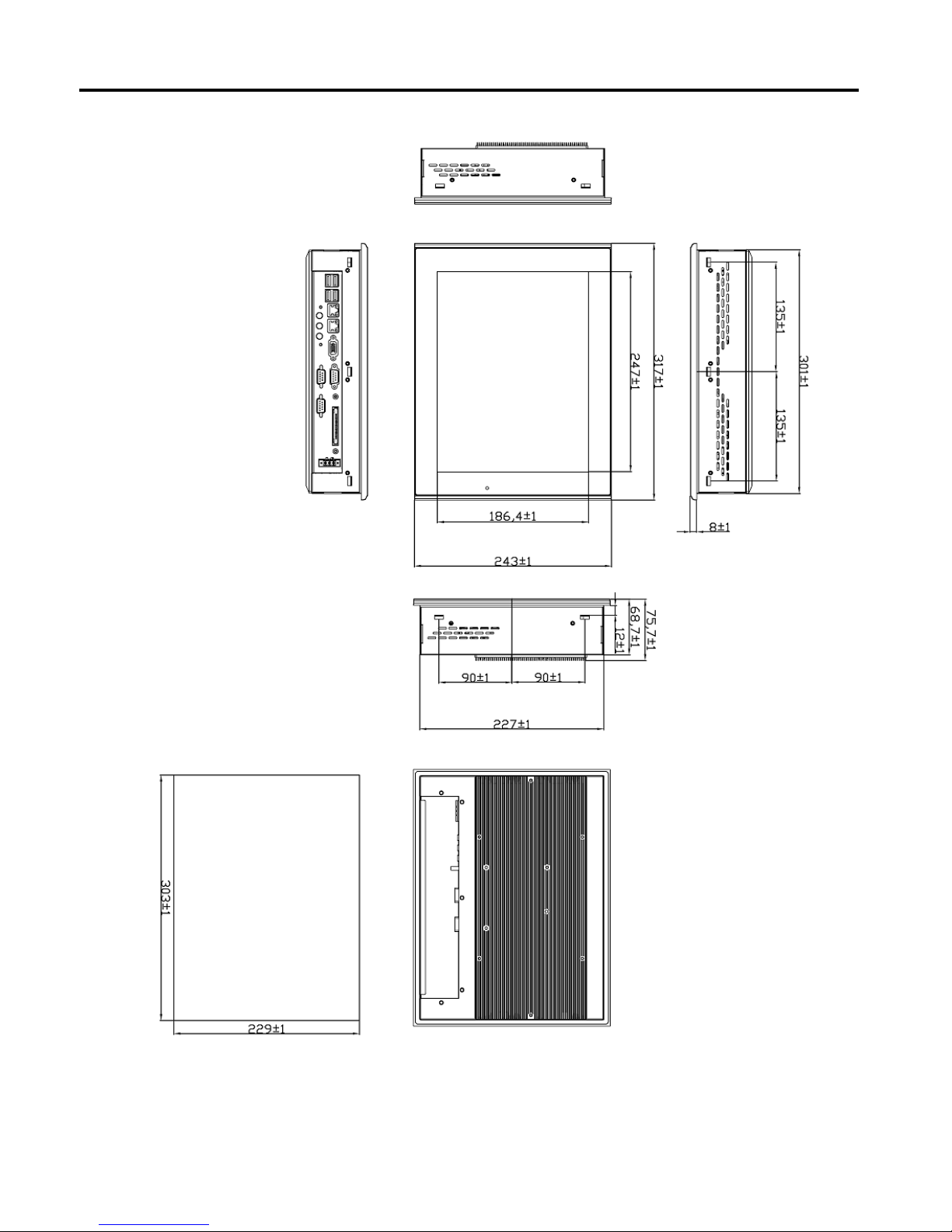
1.2 Dimensions
Chapter 1: Getting Started
Dimensions of the IMP-A120
Panel
Cut-out
IMP-A1x0T User Manual
2
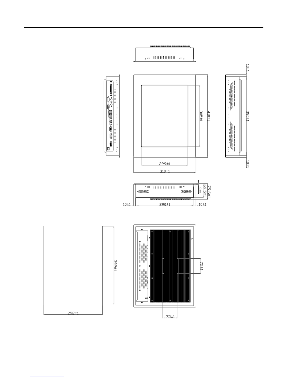
Chapter 1: Getting Started
Dimensions of the IMP-A150
Panel
Cut-out
IMP-A1x0T User Manual
3
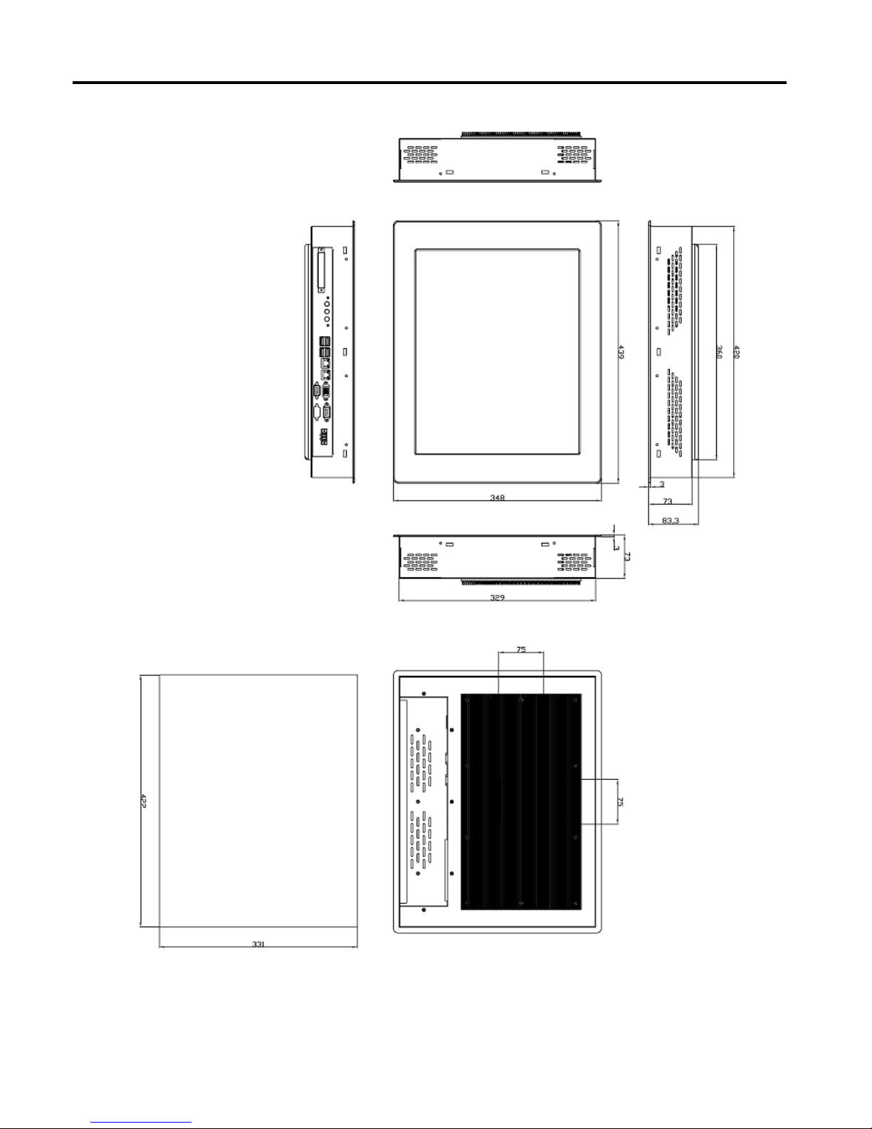
Chapter 1: Getting Started
Dimensions of the IMP-A170
Panel
Cut-out
IMP-A1x0T User Manual
4
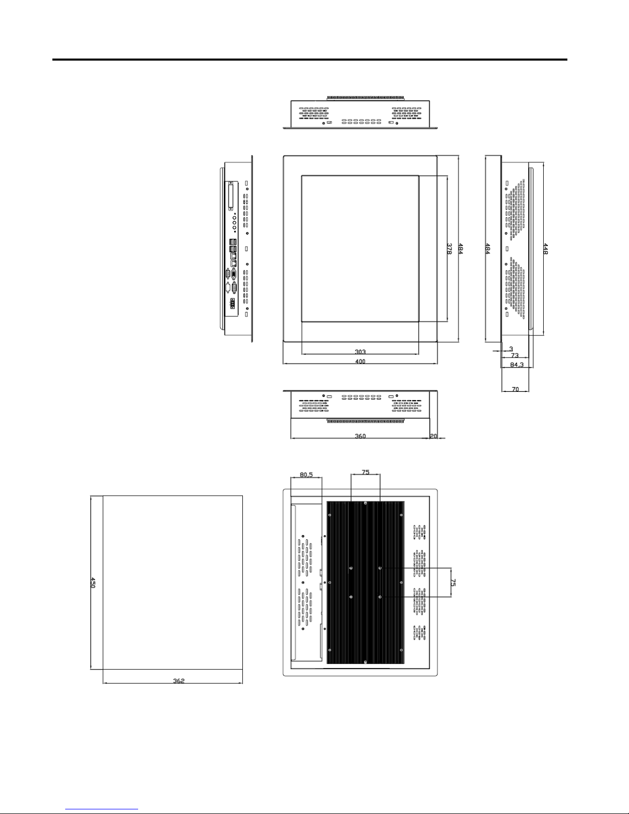
Chapter 1: Getting Started
Dimensions of the IMP-A190
IMP-A1x0T User Manual
5
Panel
Cut-out
1.3 Brief Description of the IMP-A1x0
The power-optimized IMP-A1x0 systems deliver robust performance-per-watt as an embedded HMI.
The systems are powered by an Intel Atom™ N270 1.6 GHz processor.
They come with a CompactFlash slot, 2.5” hard disk drive, DDR2 memory, 3 serial ports, 4 USB
ports, 2 Gigabit LAN ports, audio and a wide range 11~32VDC power input.
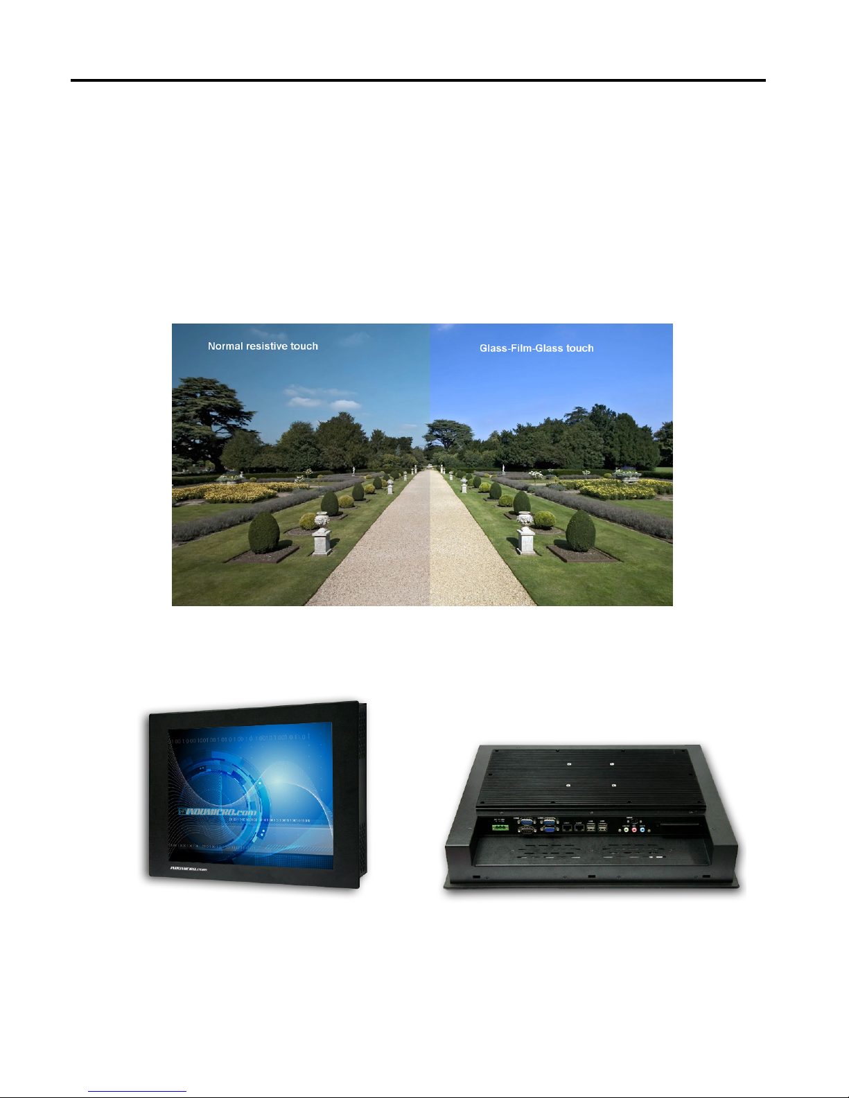
The ‘T’ models are equiped with an analog resistive touch screen while the ‘GT’ models come with
a GFG (Glass-Film-Glass) touch screen.
GFG touch screens are not only resistant to scratch and abrasion but also to most chemicals.
Apart from that, glass is transparent and does not impair the brilliance of the picture at all.
Chapter 1: Getting Started
IMP-A1x0T User Manual
6
Front and rear view of the IMP-A1x0

2.1 Operations after POST Screen
After CMOS discharge or BIOS flashing operation, the system will display the following screen for your
further operation. Press F1 key to continue or Del key to enter CMOS Setup.
Phoenix – AwardBIOS v6
.00PG, An Energy Star Ally
Copyright
© 1984-2007, Phoenix Technologies, LTD
ASB-L701 V012
Main Processor : Intel®
Atom™ 1.60GHz(133x12)
Memory Testi
ng :515008K OK + 8M shared memory
CPU Br
and Name : Intel® Atom™ CPU N270 @1.60GHz
C1E BIOS Supported
Hyper-Threading Technol
ogy CPU Detected (Hyper-Threading
Technology Enabled)
Memory Frequency F
or DDR2 533
IDE Channe
l 0 Master : None
IDE Channel 0 Slave
: None
IDE Channe
l 1 Master : None
IDE Channel 1 Slave
: None
CMOS che
cksum error – Defaults loaded
Press F1 to con
tinue, DEL to enter SETUP
11/25/2009-Silverthrone-6A79KAPXC-00
After optimizing and exiting CMOS Setup, the POST screen displayed for the first time is as follows
and includes basic information on BIOS, CPU, memory, and storage devices.
Chapter 2: BIOS Setup
IMP-A1x0T User Manual
7

Phoenix – AwardBIOS v6
.00PG, An Energy Star Ally
Copyright
© 1984-2007, Phoenix Technologies, LTD
ASB-L701 V012
Main Processor : Intel®
Atom™ 1.60GHz(133x12)
Memory Testi
ng :515008K OK + 8M shared memory
CPU Br
and Name : Intel® Atom™ CPU N270 @1.60GHz
C1E BIOS Supported
Hyper-Threading Technol
ogy CPU Detected (Hyper-Threading
Technology Enabled)
Memory Frequency F
or DDR2 533
IDE Channe
l 0 Master : None
IDE Channel 0 Slave
: None
IDE Channe
l 1 Master : None
IDE Channel 1 Slave
: None
Press DEL to enter SETU
P, F12 to Enter Boot Menu
11/25/2009-Silverthrone-6A79KAPXC-00
Press F12 key to enter Boot Menu during POST, as shown by the following figure.
Boot Menu
== Select a Boot First device ==
+
+ Hard Disk
+ CDROM
LAN
↑↓:Move Enter:Accept F4:Exit
Removable
Chapter 2: BIOS Setup
IMP-A1x0T User Manual
8

2.2 Standard CMOS Features
Press [Del] key to enter BIOS Setup utility during POST, and then a main menu containing system
summary in
formation will appear.
Standard CMOS Features
Use this menu to modify basic system configurations such as time, date and etc.
Advanced BIOS Features
Use this menu configure advanced features of Award® BIOS.
Advanced Chipset Features
Use this menu to change the values in the chipset registers and optimize your system
performance.
Integrated Peripherals
Use this menu to specify your settings for integrated peripherals.
Power Management Setup
Use this menu to specify your settings for power management.
PnP/PCI Configurations
This menu is valid only if your system supports PnP/PCI.
PC Health Status
This menu shows the current status of your PC.
Chapter 2: BIOS Setup
Phoenix – AwardBIOS CMOS Setup Utility
Standard CMOS Features Load Fail-Safe Defaults
Advanced BIOS Features Load Optimized Defaults
Advanced Chipset Features Set Administrator Password
Integrated Peripherals Set User Password
Power Management Setup Save & Exit Setup
PnP/PCI Configurations Exit Without Saving
PC Health Status
ESC : Quit
: Select Item
F10 : Save & Exit Setup
Time, Date, Hard Disk Type . . .
IMP-A1x0T User Manual
9

Load Fail-Safe Defaults
Use this menu to load Fail-Safe defaults into BIOS for the most stable, and minimal-performance
system operations.
Load Optimized Defaults
Use this menu to load factory settings into BIOS for optimal-performance system operations.
Set Administrator Password
Use this menu to set Administrator password.
Set User Password
Use this menu to set user password.
Save & Exit Setup
Save all changes to the CMOS and exit BIOS Setup.
Exit Without Saving
Abandon all changes to the CMOS and exit BIOS Setup.
The following figure shows the items of Standard CMOS Features menu, which may exclude any
modifiable subitem or contain one or more modifiable subitems. Use arrow keys to select the items
to be modified and <PgUp> or <PgDn> key to select desired settings.
Chapter 2: BIOS Setup
Phoenix – AwardBIOS CMOS Setup Utility
Standard CMOS Features
Date (mm:dd:yy) Thu, Dec 23 2009 Item Help
Time (hh:mm:ss) 20 : 11 : 17
Menu Level
IDE Channel 0 Master [ None]
IDE Channel 0 Slave [ None]
Change the day, month,
year and century
IDE Channel 1 Master [ None]
IDE Channel 1 Slave [ None]
Video
Halt On
[EGA/VGA]
[All, But Keyboard]
Base Memory 639K
Extended Memory 1038336K
Total Memory 1039360K
:Move Enter: Select +/-/PU/PD:Value F10:Save ESC:Exit F1:General Help
F5: Previous Values F6: Fail-Safe Defaults F7: Optimized Defaults
IMP-A1x0T User Manual
10

Date
This item allows you to set a desired system date (usually current date).
Day It
is a read-only and bios-defined weekday attribute ranging from Sun (Sunday) to Sat
(Saturday).
Month It is a month attribute ranging from Jan (January) to Dec (December).
Date It is a date attribute ranging from 1 to 31 and can be modified via numeric keys.
Year It is a user-defined year attribute.
Time
This item allows you to set a desired system time (usually current time).
Channel 0 Master / Channel 0 Slave
Channel 1 Master / Channel 1 Slave
Press PgUp/<+> or PgDn/<-> key to select among Manual, None and Auto type. Note that the
specification of your drive device must be in compliance with the contents of Drive Table. If the
information registered in this item is not correct, your hard disk will not work properly; if your hard
disk specification is not found or does not conform to or the Driver Table, you may select Manual
type to set the specification manually.
If you choose Manual, you will be requested to enter relevant information in the following entries.
Keyboard input is also supported. For details, you may refer to the instructive materials provided
by distributor or device manufacturer.
If a SCSI HDD device is used, set this item to "NONE".
If a CD-ROM drive is connected to the HDD port, set this item to "NONE"
AccessMode Options are: Auto, Normal, Large and LBA
Cylinder Number of cylinders
Head Number of heads
Precomp Write precompensation cylinder
Landing Zone Head landing zone
Halt on
The item allows you to determine when the system will stop.
Options are: No Errors; All Errors; All, But Keyboard
No Errors The system boot will not stop for any error.
All Errors Whenever the BIOS detects a non-fatal error, the
system boot will stop.
All, But Keyboard The system boot will not stop for a keyboard error but
stop for all other errors as detected by BIOS. (default)
The time format is <hour><minute><second>.
The date format is <day><month><date><year>.
Chapter 2: BIOS Setup
IMP-A1x0T User Manual
11

2.3 Advanced BIOS Features
CPU Feature
The item has the following options:
Delay Prior To Thermal [16 Min] (This item allows you to set the duration of entering CPU
thermal throttling.)
C1E Function [Auto] CPU Power-saving State Enable Control
Chapter 2: BIOS Setup
Phoenix – AwardBIOS CMOS Setup Utility
Advanced BIOS Features
CPU Feature [Press Enter]
Item Help
Hard Disk Boot Priority [Press Enter]
Virus Warning [Disabled]
Menu Level
CPU L1 & L2 Cache [Enabled]
Hyper-Threading Technology [Enabled]
Quick Power On Self Test [Enabled]
First Boot Device [CDROM]
Second Boot Device [Hard Disk]
Third Boot Devic
e
[LAN]
Boot Other Device [Enabled]
PXE Boot For Onboard LAN1 [Disabled]
PXE Boot For Onboard LAN2 [Disabled]
Boot Up NumLock Status [On]
Gate A20 Option [Fast]
x APC Mode Enabled
MPS Version Control For OS [1.4]
OS Select For DRAM > 64MB [Non-OS2]
Small Logo(EPA) Show [Disabled]
Security Option [Setup]
:Move Enter: Select +/-/PU/PD:Value F10:Save ESC:Exit F1:General Help
F5: Previous Values F6: Fail-Safe Defaults F7: Optimized Defaults
CPU C State Cap
ability [C1]
Execute Disable Bit [Enable]
CPU Power-saving St
ate Control
Virus Protection Technology
Hard Disk Boot Priority (IDE Storage Device Boot Priority)
This item is used to specify boot priority of IDE devices. Press "Enter" key for detailed setting.
Virus Warning
This item has two options: "Disabled" and "Enabled".
IMP-A1x0T User Manual
12

CPU L1 & L2 Cache
This item can be used to enable or disable the CPU’s primary (L1) or secondary (L2) cache. If set
to Enabled, operating speed of PC will be in
creased remarkably; if set to Disabled, the function will
be inactivated.
Hyper-Threading Technology
Enable and disable Intel's hyper-threading technology.
Quick Power On Self Test
This item is used to accelerate Power On Self Test (POST) process. If set to Enabled, BIOS will
shorten or skip some of its tests.
Enabled (default) Quick POST
Disabled Normal POST
First/Second/Third/Boot Other Device
BIOS will load the operating system according to the boot order of available devices. If disabled,
the function will be inactivated.
Boot Up NumLock Status (Default: On)
On (default) Keypad numeric keys remain valid
Off Keypad arrow keys remain valid
Gate A20 Option
Normal Gate A20 signal is controlled by keyboard controller or chipset hardware
Fast (default) Gate A20 signal is controlled by port 92 or specific programs of chipset.
APIC Mode
It refers to an advanced interrupt controller mode to meet the requirements of multi-core CPU.
MPS Version Control For OS
This item is used to specify the multiprocessor specification version of the system. It is
recommended to keep the default value (1.4).
Chapter 2: BIOS Setup
OS Selection for DRAM > 64MB
You must only select OS/2 when installing an OS/2 operating system with a RAM greater than
64MB.
The options are: Non-OS/2 (default) and OS/2.
Small Logo [EPA] Show
This item is used to determine whether the Energy Star Logo will be displayed during POST. The
options are: "Disabled" and "Enabled".
IMP-A1x0T User Manual
13

Security Option
Such option allows users to set access restrictions to both system and Setup utility
, or just Setup
utility.
System If one fails to enter a valid password in the popup box, the system will not
boot up and the Setup utility will not be accessible.
Setup (default) If one fails to enter a valid password in the popup box, the system will boot
up as usual, but the Setup utility will not be accessible.
Chapter 2: BIOS Setup
IMP-A1x0T User Manual
14
 Loading...