

Indumicro IMP-A151[G]T, IMP-A191T, IMP-A171[G]T User Manual

Industrial Panel PCs
IMP-A1x1 Series
User Manual

Warning!
___________________________________
This equipment generates, uses and can radiate radio frequency energy and if not installed and
used in accordance with the instructions m
anual may cause interference to radio communications.
It has been tested and found to comply with the limits for a Class A computing device pursuant to
FCC Rules, which are designed to provide reasonable protection against such interference when
operated in a commercial environment. Operation of this equipment in a residential area is likely
to cause interference in which case the user at his own expense will be required to take whatever
measures may be required to correct the interference.
Disclaim
er
This information in this document is subject to change without notice. In no event shall
Indumicro.com
be liable for damages of any kind, whether incidental or consequential,
arising from either the use or misuse of information in this document or in any related
materials.
Electric Shock Hazard – Do not operate the machine with its back cover removed. There are
dangerous high voltages inside.
___________________________________

Table of Contents
Chapter 1: System description
1.1
Specifications .............................................................................................................................. 1
1.2 Features of the IMP-A1x1 series ................................................................................................. 2
Chapter 2: Configuring the system
2.1
Installing a PCI add-on card ........................................................................................................ 3
2.2 Wiring diagrams serial ports ........................................................................................................ 4
Chapter 3: Touch screen configuration
3.1
Configuring a resistive touch screen ........................................................................................... 5
Chapter 4: Dimension draw
ings
4.1
Dimension drawing IMP-A151[G]T ............................................................................................ 17
4.2 Dimension drawing IMP-A171[G]T ............................................................................................ 18
4.3 Dimension drawing IMP-A191T ................................................................................................ 19

1.1 Specifications
Model IMP-A151[G]T IMP-A171[G]T IMP-A191T
System
CPU Intel® Atom™ Cedar View D2550 1.8GHz Dual Core Processor
System chipset Intel NM 10 Express
System memory 2 x 204-pin DDR3 SO-DIMM 800/1066MHz, up to 4GB
I/O Ports
USB 4 x USB 2.0 type A
Serial / Parallel 1 x RS-232, 1 x RS-232/422/485 and 1 x RS-422/485 (default)
Audio 1 x MIC-in, 1 x Line-out
External display 1 x VGA
LAN 2 x GbE
Other 1 x 2 pin remote power switch
Storage Space
HDD 1 x 320 GB SATA HDD
Card reader 1 x Externally accessible CompactFlash slot
Supported OS Windows XP Pro, Windows Standard Embedded 7 (32bit)
Expansion
Expansion slots 1 x PCI slot
Display
Display type 15” TFT-LCD 17” TFT-LCD 19” TFT-LCD
Max. resolution 1024x768 1280x1024 1280x1024
Max. color 262K 16.7M 16.7M
Luminance (cd/m2) 40 350 350 2
View angle 160° / 160° 170° / 170° 170° / 160°
Backlight lifetime 50,000 hrs
Touch Screen
Type Analog resistive on ‘T’ models, GFG on ‘GT’ models
Light transmission 80% for ‘T’ models / 90% for ‘GT’ models
Power
Input voltage DC 9~32V
Power consumption 33.2W 47.6W 48.1W
Mechanical
Construction Steel front and cover
IP rating IP65 front panel
Mounting Panel mount / VESA 75
Dimensions (w x h x d) 410 x 310 x 94.8mm 439 x 348 x 94.3mm 484 x 400 x 94.3mm
Environmental
Operating temperature 0~50°C
Storage temperature -20~60°C
Storage humidity 10 to 90% @ 40°C, non- condensing
Certification CE / FCC Class A
IMP-A1x1 Use
r Manual
1
1.2 Fea tures
of the IMP-A1x1 series
The IMP-A151
/A171 /A191 are fanless / compact panel-mount industrial PCs, which come with a 15"
(luminance of 400 cd/m²), 17" (luminance of 350 cd/m²) or 19" (luminance of 350 cd/m²) TFT LCD.
They are powered by an Intel
®
Atom D2550 1.8GHz processor.
®
These indu
strial panel PCs also feature a PCI expansion slot, three COM ports, four USB 2.0 ports,
one 2.5” HDD drive, a wide range DC 11~32V power input, etc.
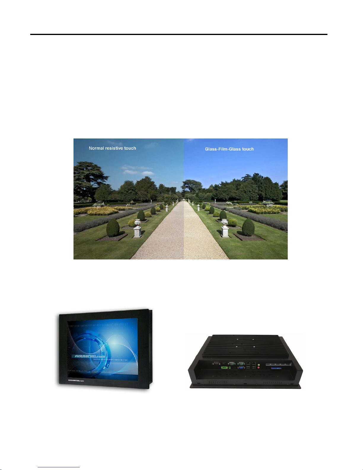
The 'T' models are equiped with an analog resistive touch screen while the 'GT' models come with a
GFG (Glass-Film-Glass) touch screen.
GFG touch screens are not only resistant to scratch and abrasion but also to most of the chemicals.
Apart from that, glass is transparent and does not impair the brilliance of the picture at all.
Front and rear view of the IMP-A171
Chapter 1: System description
IMP-A1x1 Use
r Manual
2
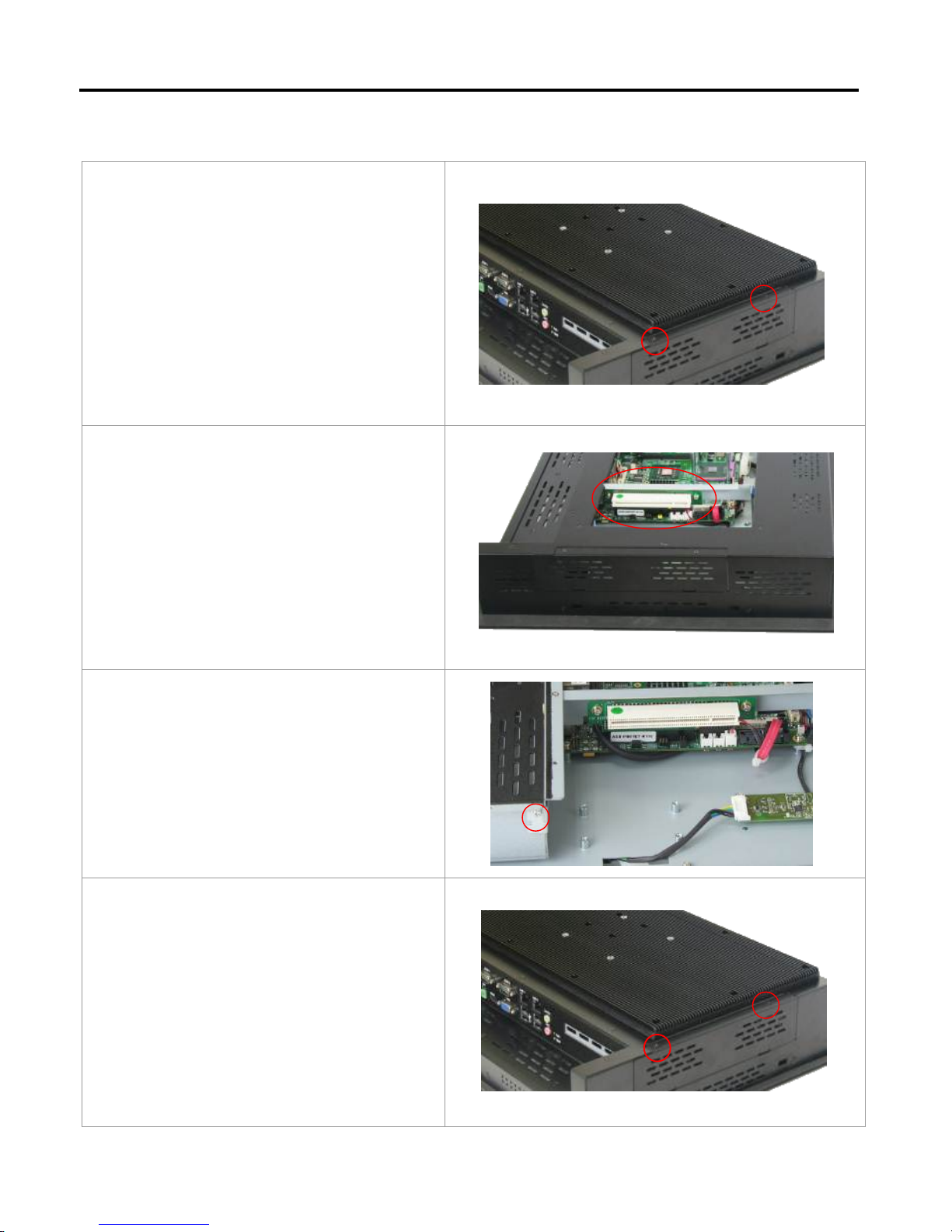
There are 2
screws to open the cover giving
you access to the PCI expansion slot.
Shown in the
picture is the PCI expansion
slot as circled. It can be inserted with any
half-size PCI add-on card.
(In this case the entire back cover of the
Panel PC is removed to give you a clear
picture of the position the PCI slot)
Slide the PCI
add-on card into the slot.
Carefully push the add-on card into the rail
of the slot.
After placing the
add-on card tighten the
screw as circled.
Close the chassis in the same way as it was
opened.
3
Chapter 2: Configuring the system
2.1 Installing a PCI add-on card
IMP-A1x1 Use
r Manual
Chapter 2: Configuring the system
2.2
Wiring d
iagrams serial ports
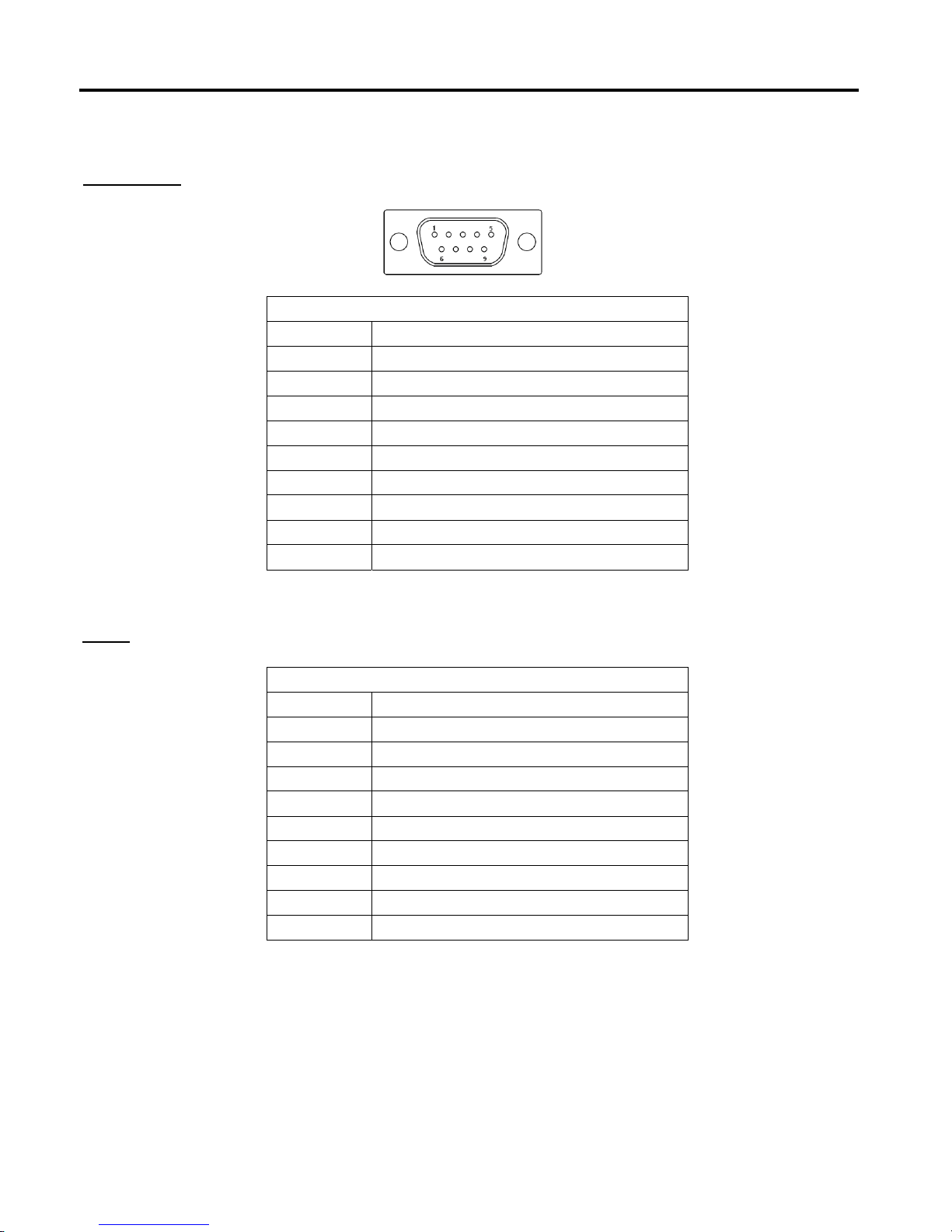
COM1/COM2
RS-232
Pin# Signal Name
1 DCD
(Data Carrier Detect)
2 RXD (Rec
eived Data)
3 TXD (Tr
ansmit Data)
4 DTR (Data
Terminal Ready)
5 Ground
6 DSR (Data
Set Ready)
7 RTS
(Request To Send)
8 CTS
(Clear To Send)
9 RI
(Ring Indicator)
RS-422/485
Pin# Signal Name
1 422_RX+
2 422_RX-
3 422_TX-
/ 485-
4 422_TX+
/ 485+
5 Ground
6 NC
7 NC
8 NC
9 NC
COM3
4
IMP-A1x1 Use
r Manual
 Loading...