

Indumicro IMP-A157, IMP-A177, IMP-A197 User Manual

User
Manual
IMP-A
15
Industrial Panel PC
/ A177 / A197
7

___________________________________
___________________________________
Warning!
This equipment generates, uses and can radiate radio frequency energy and if not installed and
used in acco
It has been tested and found to comply with the limits for a Class A computing device pursuant to
FCC Rules, which are designed to provide reasonable protection against such interference when
operated in a commercial environment. Operation of this equipment in a residential area is likely
to cause interference in which case the user at his own expense will be required to take whatever
measures may be required to correct the interference.
Electric Shock Hazard – Do not operate the machine with its back cover removed. There are
dangerous high voltages inside.
rdance with the instructions manual may cause interference to radio communications.
Disclaim
This information in this document is subject to change with
Indumicro.com be liable for damages of any kind, whether incidental or consequential,
arising from either the use or misuse of information in this document or in any related
materials.
er
out notice. In no event shall

Table of Contents
Chapter 1: Getting Started
1.1 Specifications……………………………………….……………………..1
1.2 Dimensions………………………………...………………………….......2
1.3 Brief Description…………………………………………………….……5
Chapter 2: Hardware Installation
2.1 Installation a PCI Add-on card ………………………………………..6
Safety Precautions……..…….……………………………………..…..7
2.1
Chapter 3: BIOS Setup
3.1 Introduction ..............................................................................8
3.2 Main Setup ....................................................................................10
3.3 Advanced BIOS Setup .........................................................................11
3.4 Advanced PCI/PnP Settings ............................................................... 31
3.5 Boot Setting Configuration .................................................................. 34
3.6 Security Settings ................................................................................ 37
3.7 Advanced Chipset Settings ................................................................. 38
3.8 Exit Menu............................................................................................. 44
Chapter 4: Installation
4.1 Configuring Penmount Windows 2000/XP/Vista/7 Driver.……………49
Chapter 5: Software
5.1 Software Functions ..............................................................................58
5.2 Software Function Descriptions ...........................................................59
Appendices
A Panelmounting ..............................................................................6 5

Chapter 1: Getting Started
1.1 Specifications
Specs IMP-A157[G]T IMP-A177[G]T
CPU
Chipset Intel GM45® + ICH9M-E
Model
Intel® P socket Core 2 Duo® processor, 2.26GHz
®
System Memory 200-pin DDR2 667/800 MHz SO-DIMM slot x 2, up to 4GB/slot
Display Size 15” 1024x768 TFT 17” 1280x1024 TFT 19” 1280x1024 TFT
Maximum Colors 16.7M 16.7M 16.7M
ing Angle (H/V) 150
View
Luminance
(cd/m²) 300 350 300
Backlight Lifetime
Touch Screen Type
o
/
o
140
1
70
o
/
o
160
7
50,000 Hours
Analog resistive on ‘T’ models, GFG on ‘GT’ models
Serial Port 3 COM (RS232) ports
USB Port
LAN
4 USB 2.0 ports
2 Gigabit LAN ports
Display Ports 1 x VGA, 1 x DVI-D, 1 x HDMI
Keyboard & Mouse PS/2 Keyboard & Mouse port
Audio MIC, Line-in, Line-out
IMP-A197T
o
0
/
160
o
Storage 1 x 160
GB
HDD
Expansion Slot 1 PCI Expansion slot
Power Supply 11~32VDC
Construction Heavy-duty steel chassis
Rating NEMA4/IP 65 compliant front panel
Mounting Panel / VESA75 mount
Dimensions (WxHxD) 410 x 310 x 90.8 mm 439 x 348 x 93.3 mm
Operating Temperature 0~50oC
Storage Temperature
-20~60oC
Relative Humidity 10%~90%@ 40oC, (non-condensing)
Vibration
5~17Hz, 0.1” double amplitude displacement / 17~640Hz,
1.5G acceleration peak to peak
Relative Humidity 10G Acceleration peak to peak (11 millimeters)
Certificate Meet CE / FCC Class A
484 x 400 x 94.3 mm
IMP-A1x7 User Manual
1
Chapter 1: Getting Started
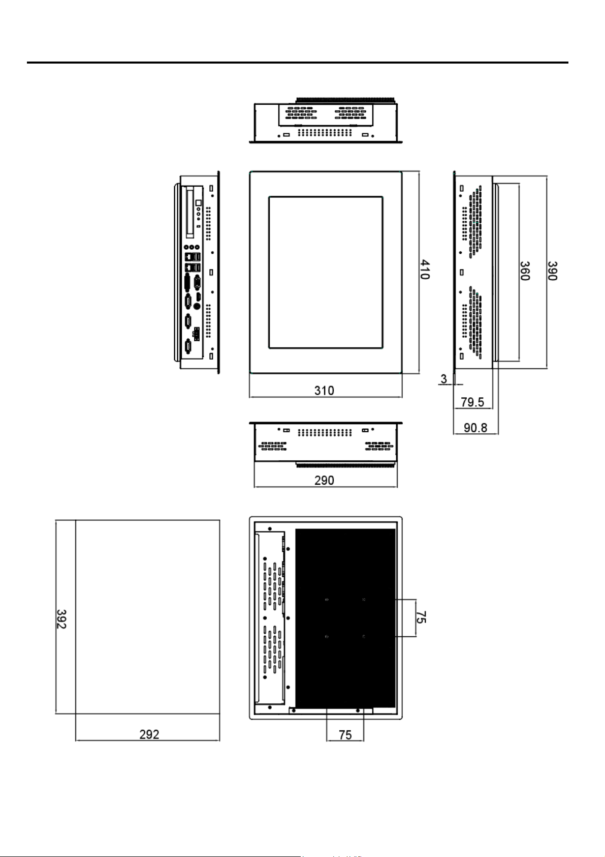
1.2 Dimensions
IMP-A1x7 User Manual
Panel
Cut-out
Dimensions of the IMP-A157
2
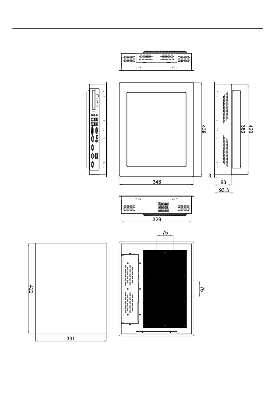
Chapter 1: Getting Started
IMP-A1x7 User Manual
Panel
Cut-out
Dimensions of the IMP-A177
3

Chapter 1: Getting Started
IMP-A1x7 User Manual
Panel
Cut-out
Dimensions of the IMP-A197
4

Chapter 1: Getting Started
1.5 Brief Description of the IMP-A157/A177/A197
The IMP-A157/A177/A197 are fanless / compact panel-mount industrial PCs, which come with a 15"
(luminance of 300 cd/m²), 17" (luminance of 350 cd/m²) or 19" (luminance of 300 cd/m²) TFT LCD.
They are powered by an Intel
These industrial panel PCs also feature a PCI expansion slot, three COM ports, four USB 2.0 ports,
one 2.5” HDD drive, a wide range DC 11~32V power input, etc.
The 'T' models are equiped with an analog resistive touch screen while the 'GT' models come with a
GFG (Glass-Film-Glass) touch screen.
GFG touch screens are not only resistant to scratch and abrasion but also to most of the chemicals.
Apart from that, glass is transparent and does not impair the brilliance of the picture at all.
®
Core 2 Duo® 2.26 GHz processor.
IMP-A1x7 User Manual
Front and rear view of the IMP-A177
5
Chapter 2: Hardware Installation
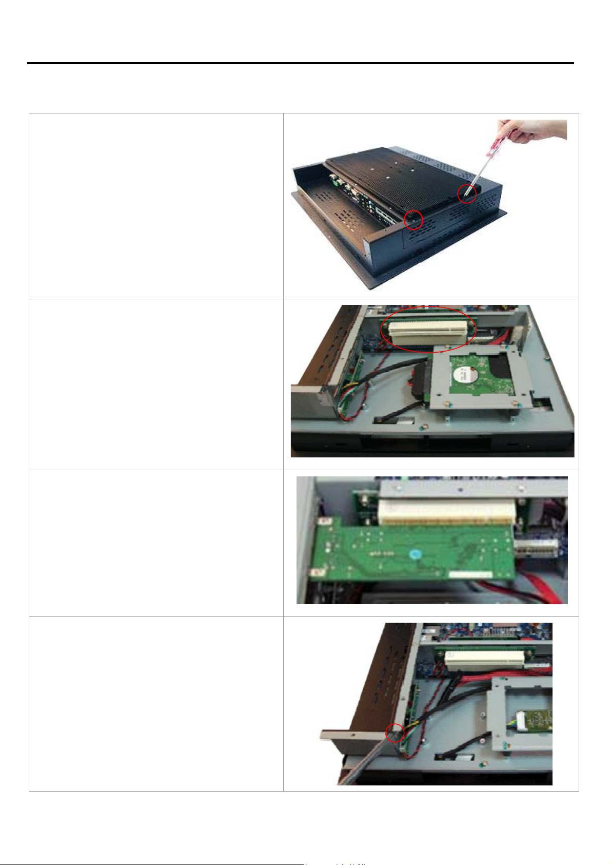
2.1 Installing a PCI Add-on Card
There are 2 screws to open the cover giving
you access to the PCI expansion slot.
Shown in the picture is the PCI expansion
slot as circled. It can be inserted with any
half-size PCI add-on card.
(In this case the entire back cover of the
Panel PC is removed to give you a clear
picture of the position the PCI slot)
Slide the PCI add-on card into the slot.
Carefully push the add-on card into the rail
of the slot.
After placing the add-on card tighten the
screw as circled.
Close the chassis in the same way as it was
opened.
IMP-A1x7 User Manual
6

Chapter 2: Hardware Installation
2.2 Safety Precautions
Follow the messages below to avoid your systems from damage:
o
Avoid your system from static electricity on all occasions.
o
Prevent electric shock. Don‘t touch any component
o
Always disconnect power when the system is not in use.
o
Disconnect power when you change any hardware devices. For instance, when you connect
a jumper or install any cards, a surge of power may damage the electronic components or
the whole system.
s of this card when the card is power-on.
IMP-A1x7 User Manual
7

Chapter 3: BIOS Setup
3.1 Introduction
3.1.1 BIOS setup program
The main BIOS setup menu is the first screen that you can navigate. Each main BIOS setup menu
option is described in this user’s guide.
The Main BIOS setup menu screen has two main frames. The left frame displays all the options that
can be configured. “Grayed-out” options cannot be configured.
The right frame displays the key legend. Above the key legend is an area reserved for a text message.
When an option is selected in the left frame, it is highlighted in white.
The default BIOS settings for this motherboard apply for most
conditions to ensure optimum performance. If the system
becomes unstable after changing any BIOS settings, load the
default settings to ensure system compatibility and stability.
Select the Load Default Settings item under the Exit Menu.
The BIOS setup screens shown in this section are for reference
purposes only, and may not exactly match what you see on
your screen.
IMP-A1x7 User Manual
8

Chapter 3: BIOS Setup
3.1.2 Legend Box
The BIOS setup/utility uses a key-based navigation system called hot keys. Most of the BIOS setup
utility hot keys can be used at any time during the setup navigation process.
These keys include <F1>, <F10>, <Enter>, <ESC>, <Arrow> keys, and so on.
The keys in the legend bar allow you to navigate through the various setup menus.
Key(s) Function Description
, Left/Right The Left and Right <Arrow> keys allow you to select an setup screen.
For example: Main screen, Advanced screen, Chipset screen, and so
on.
, Up/Down The Up and Down <Arrow> keys allow you to select an setup item or
sub-screen.
+, - Plus/Minus The Plus and Minus <Arrow> keys allow you to change the field value
of a particular setup item.
For example: Date and Time.
Tab The <Tab> key allows you to select setup fields.
F1 The <F1> key allows you to display the General Help screen.
Press the <F1> key to open the General Help screen.
F10 The <F10> key allows you to save any changes you have made and
exit Setup. Press the <F10> key to save your changes.
ESC The <Esc> key allows you to discard any changes you have made
and exit the Setup. Press the <Esc> key to exit the setup without
saving your changes.
Enter The <Enter> key allows you to display or change the setup option
listed for a particular setup item. The <Enter> key can also allow you
to display the setup sub- screens.
3.1.3 List Box
This box appears only in the opening screen. The box displays an initial list of configurable items in the
menu you selected.
3.1.4 Sub-menu
Note that a right pointer symbol () appears to the left of certain fields. This pointer indicates that you
can display a sub-menu from this field. A sub-menu contains additional options for a field parameter.
To display a sub-menu, move the highlight to the field and press <Enter>. Use the legend keys to
enter values and move from field to field within a sub-menu as you would within a menu. Use the
<Esc> key to return to the main menu.
IMP-A1x7 User Manual
9
Chapter 3: BIOS Setup
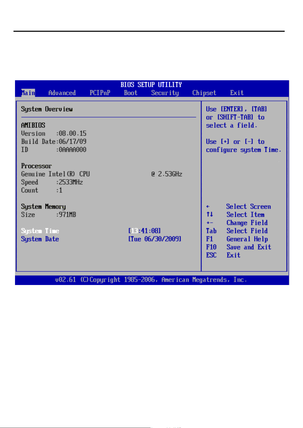
3.2 Main Setup
When you first enter the Setup Utility, you will enter the Main setup screen. You can always return to
the Main setup screen by selecting the Main tab. There are two Main Setup options. They are
described in this section. The Main BIOS Setup screen is shown below.
System Time/System Date
Use this option to change the system time and date. Highlight System Time or System
Date using the <Arrow> keys. Enter new values through the keyboard. Press the <Tab> key or
the <Arrow> keys to move between fields. The date must be entered in MM/DD/YY format. The
time is entered in HH:MM:SS format.
Note: The time is in 24-hour format. For example, 5:30 A.M. appears as 05:30:00, and
5:30P.M. as 17:30:00.
IMP-A1x7 User Manual
10
Chapter 3: BIOS Setup
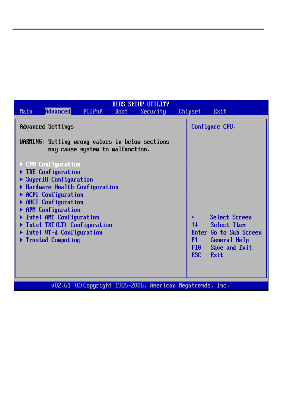
3.3 Advanced BIOS Setup
Select the Advanced tab from the setup screen to enter the Advanced BIOS Setup screen.
You can select any of the items in the left frame of the screen, such as SuperIO Configuration, to go to
the sub menu for that item. You can display an Advanced BIOS Setup option by highlighting it using
the <Arrow> keys. All Advanced BIOS Setup options are described in this section. The Advanced
BIOS Setup screen is shown below.
The sub menus are described on the following pages.
IMP-A1x7 User Manual
11
Chapter 3: BIOS Setup
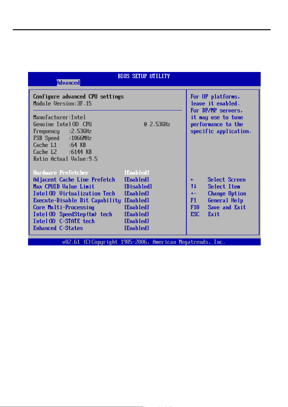
3.3.1 CPU Configuration Setting
You can use this screen to select options for the CPU Configuration Settings.
A description of the selected item appears on the right side of the screen.
Hardware Prefetcher
The choices of Hardware Prefetcher which pre-fetches data from memory to L2 cache are
Disabled, and Enabled.
Adjacent Cache Line Prefetch
The choices of Adjacement Cache Line Prefetch which automatically fetches an extra 64-byte
cache line are Enabled, Disabled.
Max CPUID Value Limit
The choices of Max CPUID Value Limit are Disabled, and Enabled.
Intel® Virtualization Tech
The choices of Intel® Virtualization Tech are Enabled, Disabled.
IMP-A1x7 User Manual
12

Chapter 3: BIOS Setup
Execute-Disable Bit Capability
The choices of Execute-Disable Bit Capability are Enabled, Disabled.
Core Multi-Processing
The item is to enable or disable the Core Multi-processing function.
Intel® SpeedStep™ tech
The choices of Execute-Disable Bit Capability are Enabled, Disabled.
Intel® C-State tech
The choices of Execute-Disable Bit Capability are Enabled, Disabled.
Enhanced C-States
The choices of Execute-Disable Bit Capability are Enabled, Disabled.
IMP-A1x7 User Manual
13
Chapter 3: BIOS Setup
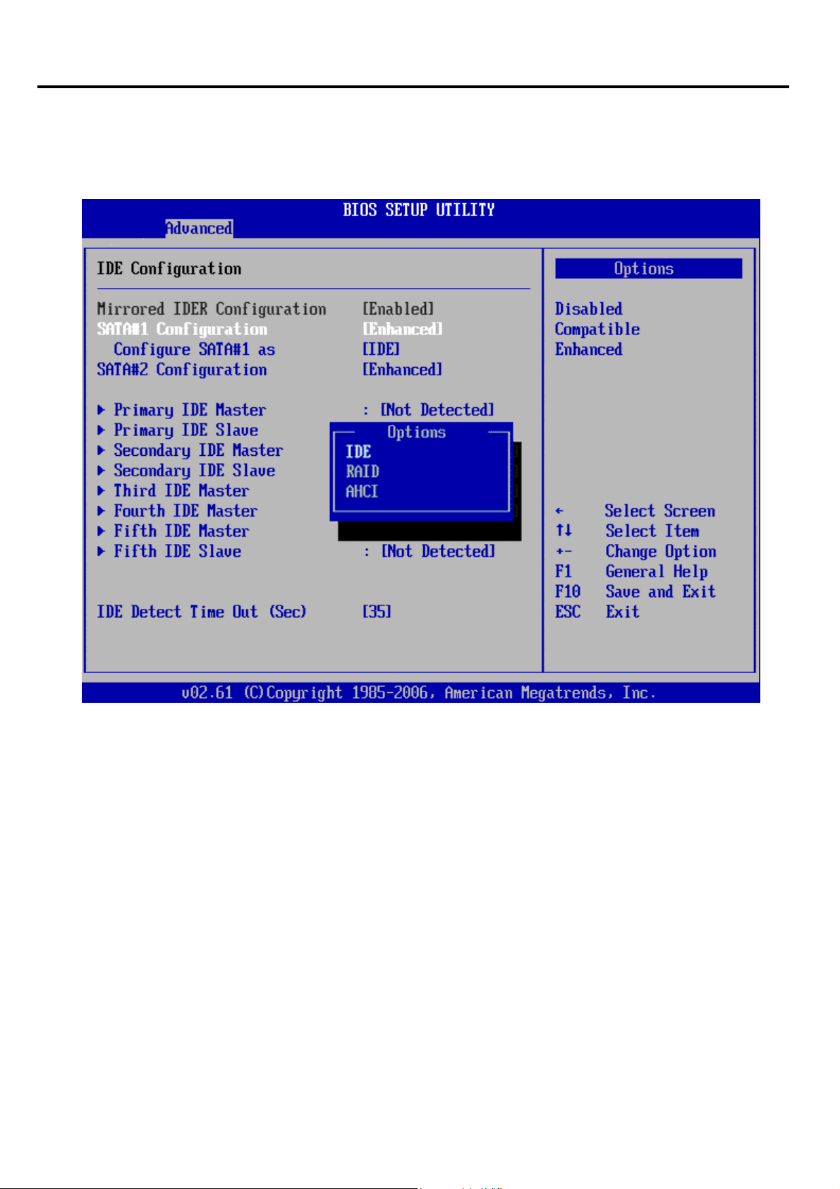
3.3.2 IDE Configuration Setting
You can use this screen to select options for the IDE Configuration Settings.
A description of the selected item appears on the right side of the screen.
Mirrored IDER Configuration
The choices of Mirrored IDER configuration are Disabled, and Enabled.
SATA#1 Configuration
The choices of SATA configuration are Disabled, Compatible, and Enhanced.
Configure SATA #1 as
This item allows to configure SATA as IDE, RAID, or AHCI.
SATA#2 Configuration
The choices of SATA configuration are Disabled and Enhanced.
Primary/Secondary IDE Master/Slave, Third/Fourth IDE Master, Fifth IDE Master/Slave
Select one of the hard disk drives to configure it. Press <Enter> to access its the sub menu. The
options on the sub menu are described in the following sections.
IMP-A1x7 User Manual
14

Chapter 3: BIOS Setup
IDE Detect Time Out (Sec)
Set this option to stop the AMIBIOS from searching for IDE devices within the specified number of
seconds. Basically, this allows you to fine-tune the settings to allow for faster boot times. Adjust
this setting until a suitable timing that can detect all IDE disk drives attached is found.
The default setting is 35.
Option Description
0 This value is the best setting to use if the onboard IDE controllers are set to a
specific IDE disk drive in the AMIBIOS.
5 Set this value to stop the AMIBIOS from searching the IDE bus for IDE disk
drives in five seconds. A large majority of ultra ATA hard disk drives can be
detected well within five seconds.
10 Set this value to stop the AMIBIOS from searching the IDE bus for IDE disk
drives in 10 seconds.
15 Set this value to stop the AMIBIOS from searching the IDE bus for IDE disk
drives in 15 seconds.
20 Set this value to stop the AMIBIOS from searching the IDE bus for IDE disk
drives in 20 seconds.
25 Set this value to stop the AMIBIOS from searching the IDE bus for IDE disk
drives in 25 seconds.
30 Set this value to stop the AMIBIOS from searching the IDE bus for IDE disk
drives in 30 seconds.
35 35 is the default value. It is the recommended setting when all IDE connectors
are set to AUTO in the AMIBIOS setting.
Note: Different IDE disk drives take longer for the BIOS to locate than others do.
IMP-A1x7 User Manual
15
Chapter 3: BIOS Setup
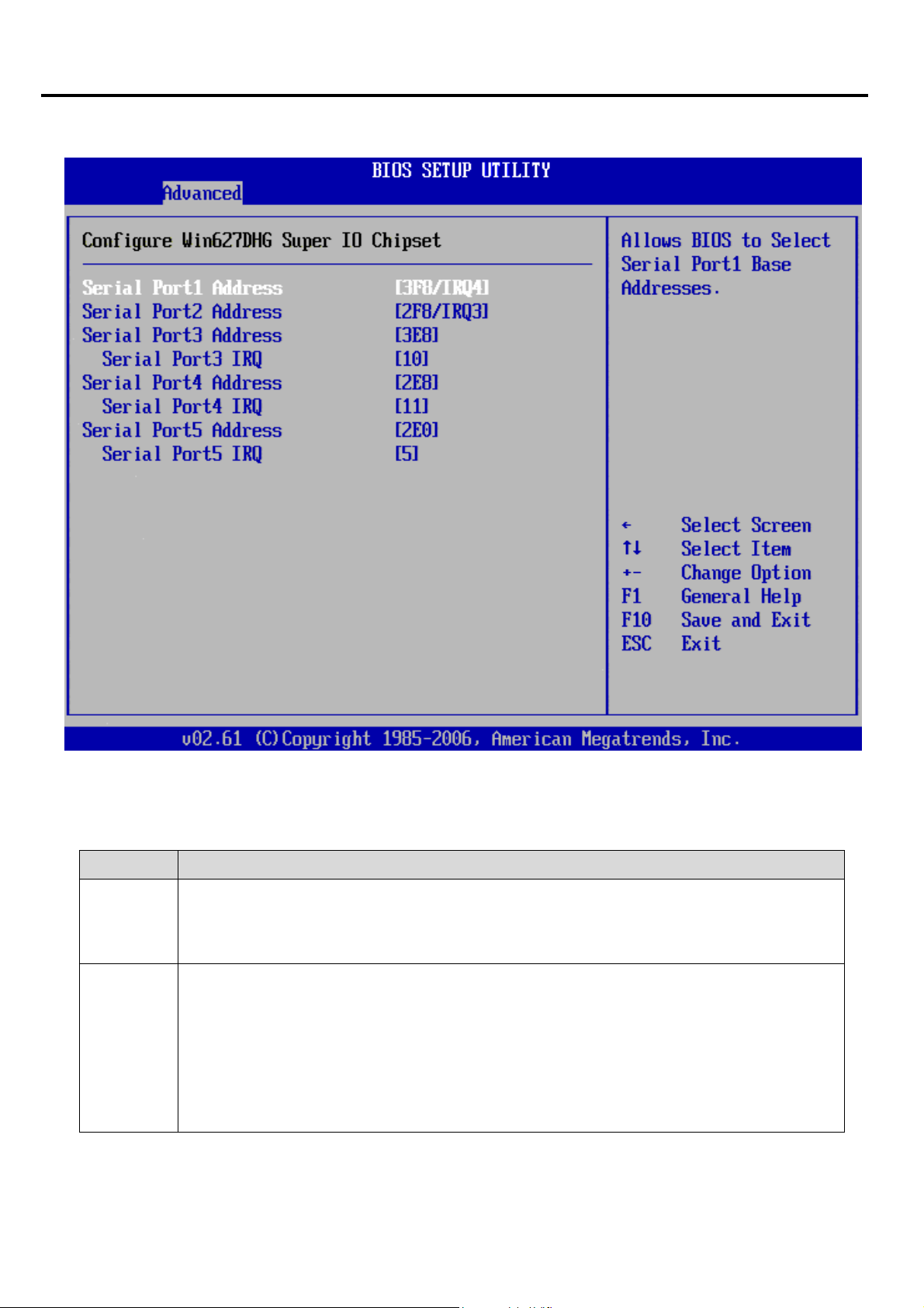
3.3.3 Super I/O Configuration
Serial Port1 Address
This option specifies the base I/O port address and Interrupt Request address of serial port 1. The
Optimal setting is 3F8/IRQ4.
Option Description
Disabled Set this value to prevent the serial port from accessing any system resources.
When this option is set to Disabled, the serial port physically becomes
unavailable.
3F8/IRQ4 Set this value to allow the serial port to use 3F8 as its I/O port address and
IRQ4 for the interrupt address. This is the default setting. The majority of serial
port 1 or COM1 ports on computer systems use IRQ4 and I/O Port 3F8 as the
standard setting. The most common serial device connected to this port is a
mouse. If the system will not use a serial device, it is best to set this port to
Disabled.
IMP-A1x7 User Manual
16

Chapter 3: BIOS Setup
Serial Port2 Address
This option specifies the base I/O port address and Interrupt Request address of serial port 2. The
Optimal setting is 2F8/IRQ3.
Option Description
Disabled Set this value to prevent the serial port from accessing any system resources.
When this option is set to Disabled, the serial port physically becomes
unavailable.
2F8/IRQ3 Set this value to allow the serial port to use 2F8 as its I/O port address a n d IRQ
3 for the interrupt address. This is the default setting. The majority of serial port
2 or COM2 ports on computer systems use IRQ3 and I/O Port 2F8 as the
standard setting. The most common serial device connected to this port is an
external modem. If the system will not use an external modem, set this port to
Disabled.
Note: Most internal modems require the use of the second COM port and use
3F8 as its I/O port address and IRQ 4 for its interrupt address. This requires
that the Serial Port2 Address be set to Disabled or another base I/O port
address and Interrupt Request address.
Serial Port3 Address
This option specifies the base I/O port address of serial port 3. The Optimal setting is 3E8.
Serial Port3 IRQ
This option specifies the Interrupt Request address of serial port 3. The Optimal setting is 10.
Option Description
Disabled Set this value to prevent the serial port from accessing any system resources.
When this option is set to Disabled, the serial port physically becomes
unavailable.
3E8/IRQ10 Set this value to allow the serial port to use 3E8 as its I/O port address and
IRQ10 for the interrupt address. This is the default setting. If the system will not
use a serial device, it is best to set this port to Disabled.
IMP-A1x7 User Manual
17

Chapter 3: BIOS Setup
Serial Port4 Address
This option specifies the base I/O port address of serial port 4. The Optimal setting is 2E8.
Serial Port4 IRQ
This option specifies the Interrupt Request address of serial port 4. The Optimal setting is 11.
Option Description
Disabled Set this value to prevent the serial port from accessing any system resources.
When this option is set to Disabled, the serial port physically becomes
unavailable.
2E8/IRQ11 Set this value to allow the serial port to use 2E8 as its I/O port address and
IRQ11 for the interrupt address. This is the default setting. If the system will not
use a serial device, it is best to set this port to Disabled.
Serial Port5 Address
This option specifies the base I/O port address of serial port 5. The Optimal setting is 2E0.
Serial Port5 IRQ
This option specifies the Interrupt Request address of serial port 5. The Optimal setting is 5.
Option Description
Disabled Set this value to prevent the serial port from accessing any system resources.
When this option is set to Disabled, the serial port physically becomes
unavailable.
2E0/IRQ5 Set this value to allow the serial port to use 2E0 as its I/O port address and
IRQ5 for the interrupt address. This is the default setting. If the system will not
use a serial device, it is best to set this port to Disabled.
IMP-A1x7 User Manual
18
 Loading...