

Indumicro IMO-A080 User Manual
Open Frame
User
IMO-A080
Manual
Monitor

___________________________________
___________________________________
Warning!
This equipment generates, uses and can radiate radio frequency energy and if not installed and
used in accordance with the instructions manual may cause interference to radio communications.
It has been tested and found to comply with the limits for a Class A computing device pursuant to
FCC Rules, which are designed to provide reasonable protection against such interference when
operated in a commercial environment. Operation of this equipment in a residential area is likely
to cause interference in which case the user at his own expense will be required to take whatever
measures may be required to correct the interference.
Electric Shock Hazard – Do not operate the machine with its back cover removed. There are
dangerous high voltages inside.
Disclaim
This information in this document is subject to change wit
Indumicro.com be liable for damages of any kind, whether incidental or consequential,
arising from either the use or misuse of information in this document or in any related
materials.
er
hout notice. In no event shall

Table of Contents
Chapter 1: Getting Started
1.1 Features…...……………………………………………………….…..…..…1
1.2 Sp
1.3 Dimensions…………...………………………...………………………….…2
1.4 Brief Description......................................................................................3
1.5 Display Mode………...……………………………………………………….3
Chapter 2: On Screen Display (OSD)
2.1 Back Side Controls…………………………
2.2 OSD Controls…………………..……………………………………………..5
2.3 Main Menu …..………..……………………………………………………..6
ecifications…………………………………………. ...……………...….1
…………………….…..…….4
Chapter 3: Installation
3.1 Configuring PenMount Windows 2000/XP/Vista/7 Driver
……………..6
Chapter 4: Software
4.1 Software Functions………………………………………………………..17
4.2
Software Function Descriptions……………………………………….…18

Chapter 1: Getting Started
1.1 Features
●
8” SVGA color TFT
●
Optional resistive touch screen
●
●
Steel chassis
●
OSD on the rear side
1.2 Specifications
Display
●
Display:
●
Maximum resolution: 800 x 600
●
Maximum colors: 256K
●
Luminance: 350 cd/m²
8” SVGA color TFT LCD display
LCD display
●
Viewing angle: 30° (H/V)
●
Backlight life: 40,000 hours
●
OSD control: Yes
●
Touch screen: analog resistive
●
OS compatibility: Win 95/98, XP, 2000, NT4.0, Vista, 7, QNX, Linux
●
Power Supply: 12V DC @0.9A
1 °/
120
(optional)
Mechanical
●
Construction: steel chassis
●
Input signal: analog RGB
●
OSD on the rear side
●
Dimensions: 208 x 148 x 42mm (W x H x D)
●
Gross W
Environmental
● Operating temperature: 0 to 50
eight: 1.1 kg
o
C (32 to 113oF)
● Storage temperature: -20 to 6
●
Relative humidity: 10 to 95% @4
Vibration: 1G peak, 5~500Hz (at random)
●
● Shock: 15G peak acceleration (11 msec.duration)
● EMC: Meet CE, FCC Class A
IMO-A080 User Manual
0oC (-4 to 140oF)
0oC, non-condensing, without touch screen
1
Chapter 1: Getting Started
Ordering Information
IMO-A080 8” SVGA Open frame monitor
IMO-A080T 8” SVGA Open frame monitor with resistive touch screen
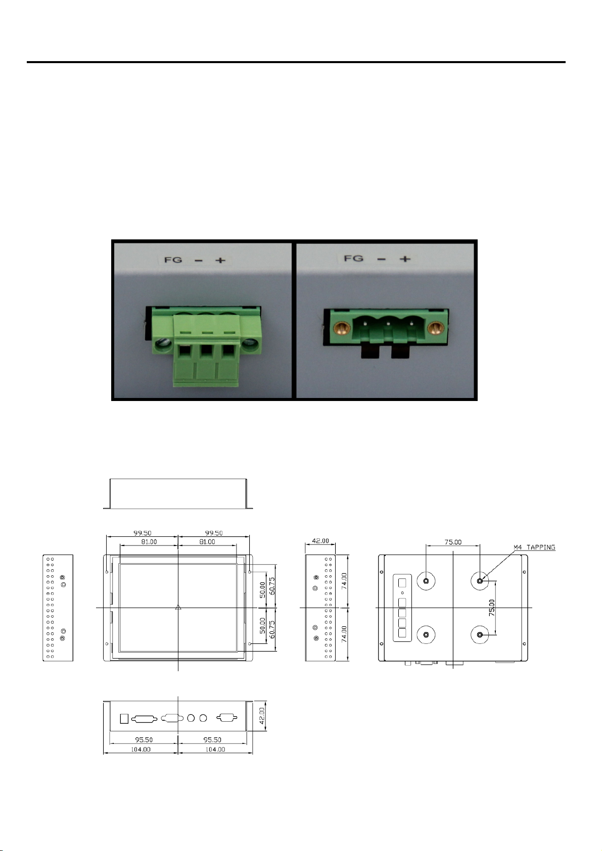
IMO-AOVDC Upgrade to 11~32VDC power input and DVI-D input
12V/60W External power adapter
Option
Power Connection for IMO-AOVDC
1.3 Dimensions
IMO-A080 User Manual
2
Chapter 1: Getting Started
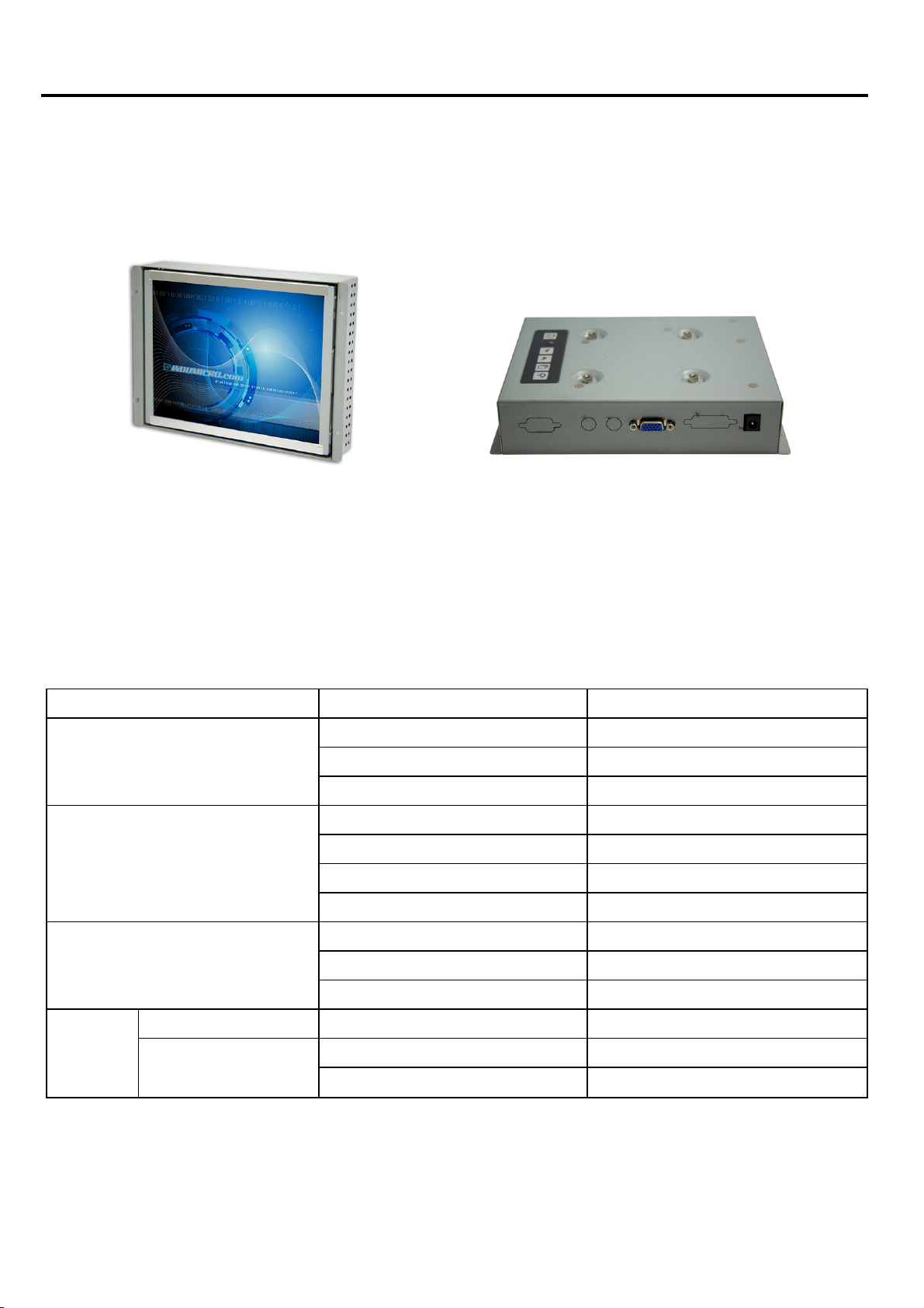
1.4 Brief Description of the IMO-A080
The IMO-A080 open frame monitor features an excellent viewing ability for monitoring and control
applications. It is available with resistive touch screen that is easy to use and maintain.
Front and back view of the IMO-A080
1.5 Display Mode
Display Mode Hori. Sync (KHz) Vert. Sync. (Hz)
VGA 640 x 480 38 72
SVGA 800 x 600 38 60
XGA 1024 x 768 56 70
SXGA
1152 x 864 68 75
1280 x 1024
31 60
38
35
48
47
48
60
64
80
75
56
72
75
60
75
60
75
IMO-A080 User Manual
3
Chapter 2: On Screen Display (OSD)
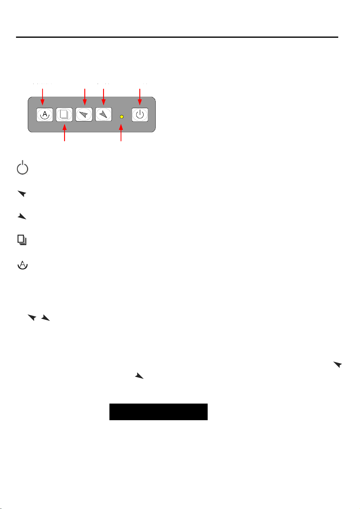
2.1 Back side OSD Functions
Auto Adjus
Shift the icon to the right side or shif
Shift the icon to the le
Menu: T
t Up/Left Down/Right Power
Menu/Entry
Power switch: To
o
enter OSD menu for related icon and item.
Power Indicator
tur
n ON or OFF the power
f
t side or shift it down
t it up
Auto Button: One-touch auto adjustment
1.) Getting into Burn-in Mode
Before setti
the
of your screen. Now it can be put into the burn-in mode for changing colors.
2.) Getting Out of Burn-in Mode
Before getting out of the burn-in mode, please first disconnect the AC power cord. Then press the
button (If not workable, press the button and don’t let them go) until the AC power cord is
connected. Please don’t let your
wording of “RGB” appears on the top lef
non-signal entry situation, if is seen, exit is thus successfully made.
ng into a burn-in mode, first disconnect the AC power cord. Then press (don’t let them go)
buttons until the AC power cord is connected and the “RGB” appears on the top lef
fingers go until the AC power cord is connected again and the
t corner of your screen, and wait for 3 seconds. Under the
Cable Not Connected
t
corner
IMO-A080 User Manual
4
Chapter 2: On Screen Display (OSD)
2.2 OSD Controls
To make any adjustment, select the following:
1. Press
2. Select the icon that you wish to adjust with the (
3. Press
4. Press
(Menu) to show the OSD menu or disable the OSD menu.
/ or +/-) key in the menu.
(Menu) and then choose the item with the (
(Menu) and then adjust the quality with the (
/ or +/-) key.
/ or +/-) key.
t
1.) If the “RGB” is still on the top lef
choose “Reset”, and then Yes, and press . When the screen goes black, disconnect power
and repeat the above steps.
If the “RGB” is not found, disconnect th
2.)
(don’t let them go) until the AC power cord is connected, and wait for 2 to 3 seconds. When
“RGB” appears, repeat the above steps.
corner of the screen, press
e AC power cord first. Then press the
to enter “Miscellaneous” and
buttons
3.) Functions of OSD Keys
IMO-A080 User Manual
5
Chapter 2: On Screen Display (OSD)
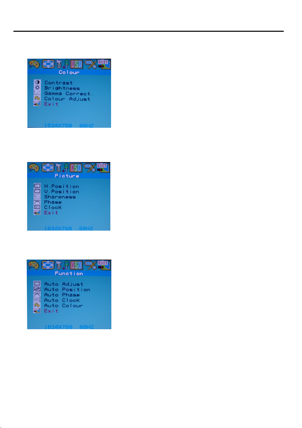
2.3 Main Menu
In the Colour menu, there are the following items:
z Contrast
z Brightness
z Gamma Correct
z Colour Adjust
z Exit
For Picture, check out the following:
z H. Position: Shifts picture left or right
z V. Position: Shifts picture up or down
z Sharpness: Fine-tuning of image sharpness
z Phase: Allows to fine-tune display quality
z Exit
For Function, check out the following:
Auto Adjust
z
z Auto Position
z Auto Phase
z Auto Clock
z Auto Colour
z Exit
IMO-A080 User Manual
6
 Loading...