

Indumicro IMM-L30D User Manual
User Manual
IMM-L30D
DIN-Rail Box PC

___________________________________
___________________________________
Warning!
This equipment generates, uses and can radiate radio frequency ener
used in accordance with the instructions manual may cause interference to radio communications.
It has been tested and found to comply with the limits for a Class A computing device pursuant to
FCC Rules, which are designed to provide reasonable protection against such interference when
operated in a commercial environment. Operation of this equipment in a residential area is likely
to cause interference in which case the user at his own expense will be required to take whatever
measures may be required to correct the interference.
Electric Shock Hazard – Do not operate the machine with its back cover removed. There are
dangerous high voltages inside.
gy and if not installed and
Disclaim
This information in this document is subject to change wi
Indumicro.com be liable for damages of any kind, whether incidental or consequential,
arising from either the use or misuse of information in this document or in any related
materials.
er
thout notice. In no event shall

Table of Contents
Chapter 1: Introduction
System Specication
Front Panel Features. . . . . . . . . . . . . . . . . . . . . . . . . . . . . . . . . . . . . . . . . . . . 2
Top and Bottom Panel Features . . . . . . . . . . . . . . . . . . . . . . . . . . . . . . . . . . . . 3
Dimensions . . . . . . . . . . . . . . . . . . . . . . . . . . . . . . . . . . . . . . . . . . . . . . . . . 4
Chapter 2: Hardw
Preparing the Hardw
Installing the System Memory . . . . . . . . . . . . . . . . . . . . . . . . . . . . . . . . . . . . . 5
Installing a CompactFlash Card. . . . . . . . . . . . . . . . . . . . . . . . . . . . . . . . . . . . . 5
Connecting Power . . . . . . . . . . . . . . . . . . . . . . . . . . . . . . . . . . . . . . . . . . . . . 5
Chapter 3: Motherboard Informa
Motherboard Lay
Jumper Settings . . . . . . . . . . . . . . . . . . . . . . . . . . . . . . . . . . . . . . . . . . . . . . 7
. . . . . . . . . . . . . . . . . . . . . . . . . . . . . . . . . . . . . . . . . . . 1
are Setup
are Installation. . . . . . . . . . . . . . . . . . . . . . . . . . . . . . . . . . 5
tion
out . . . . . . . . . . . . . . . . . . . . . . . . . . . . . . . . . . . . . . . . . . . 6
Chapter 4: BIOS Settings
Accessing the BIOS menu . . . . . . . . . . . . . . . . . . . . . . . . . . . . . . . . . . . . . . . . 9
Navigating the BIOS menu . . . . . . . . . . . . . . . . . . . . . . . . . . . . . . . . . . . . . . . 9
The Main menu . . . . . . . . . . . . . . . . . . . . . . . . . . . . . . . . . . . . . . . . . . . . . . 10
Advanced Settings . . . . . . . . . . . . . . . . . . . . . . . . . . . . . . . . . . . . . . . . . . . .20
Boot Settings . .
Security Settings . . . . . . . . . . . . . . . . . . . . . . . . . . . . . . . . . . . . . . . . . . . . . .21
Exit Menu . . . . . . . . . . . . . . . . . . . . . . . . . . . . . . . . . . . . . . . . . . . . . . . . . .22
. . . . . . . . . . . . . . . . . . . . . . . . . . . . . . . . . . . . . . . . . . . . . .20
Appendices
Programming the Watchdog Timer . . . . . . . . . . . . . . . . . . . . . . . . . . . . . . . . . .23
Digital Input/Output Control on the GPIO port . . . . . . . . . . . . . . . . . . . . . . . . . . .28
Chapter 1: Introduction
Introduction
Thank you for choosing the IMM-L30D. The IMM-L30D is
is an industrial c
density of serial communication and digital I/O ports in a
compact design (69.1x165x127mm[W/H/D]).
The IMM-L30D has an outstanding industrial and mechanical
design. It can be placed on the desk or mounted on the DINrails to rotate along its DIN-rail attachment, thereby easing
the access of the I/O interface. This reduces maintenance
effort when the device is installed in a ticketing machine,
medical equipment, or other apparatus where access is
limited.
The IMM-L30D features a solid and sealed aluminum
extrusion housing. It provides dust resistance and superior
protection from EMI.
Here is a summary of the key capabilities of IMM-L30D:
Onboard Intel N450•
Six RS-232/422/485 ports with automatic flow control•
Four 10/100/1000 Base-T RJ-45 ports•
Four USB ports (2 external and 2 internal pin headers•
Onboard VGA interface featuring the 3rd generation •
Intel graphics core which supports resolutions up
to 1920 x 1080
omputer featuring high availability and
System Specification
FEATURE
Platform
Memory
Storage
Networking
I/O
Hardware
Monitor
OS Supported
onmental
Envir
Parameters
DESCRIPTION IMM-L30D
Form Factor DIN-Rail
Processor Intel N450
Chipset Intel ICH8M
BIOS AMI Flash BIOS
Memory IC On Board No
Memory Socket
Max Memory 2GB (1 x 2GB Module)
Compact Flash
Disk Drive
Controller (Interface) 4 x Realtek RTL8111D
COM Ports
USB 2.0
VGA 1 x DB15
LAN 4 x RJ45 GbE
DIDO 4 x DI, 4 x DO
Internal CF 1
Controller
Watchdog timer Yes (1~255 level)
Operating Temperature
(With Industrial Components:
CF, Memory, SSD, HDD)
Operating Temperature
(With Commercial Components)
1.6GHz
SODIMM x 1 (up to 2GB
per slot)
1 x CF Socket Type I/II
(internal/external options
available)
2.5 Hard Disk or Solid
"
State Disk
6 x RS-232/422/485
Hardware auto-ow control
2 (w/ 2 additional 2.54 pin
headers)
Fintek F81865F-I integrated
hardware monitor
Windows XP, Embedded XP,
Vista, 7
-20°~55°C / 14°~131°F
-5°C~45°C / 23°~113°F
IMM-L30D User Manual
Dimensions
Power
Compliance
Extended Operating Temperature Tested
W x H x D (mm) 69.1 x 165 x 127 mm
Weight 1.4Kg
DC Power +12V ~ 36V DC in
Adapter 60W Adapter
Standard CE, FCC, RoHS
N/A
1
Chapter 1: Introduction
Front P
anel Featur
F1
VGA Port
es
F2
F1
F3
LAN2 LAN4
LAN1 LAN3
12345 678910
11121314151617181920
F4
F5
F6
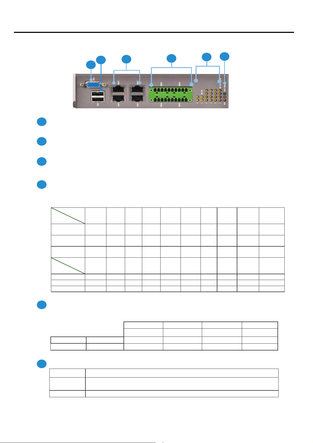
Port for the connection of a monitor using a suitable DB-15 cable .
F2
Two USB 2.0 type A ports
Connects to any USB device, for example, a flash drive.
F3
Four 10/100/1000Mbps LAN ports
Using suitable RJ-45 cable, you can connect IMM-L30D System to a computer, or to any other piece of equipment
that has an Ethernet connection such as a hub or a switch.
F4
20-pin Phoenix Contact Terminal Block
This connector can be connected for 4 Com ports (COM4: Pin 1~5, Com3: Pin 6~10, Com2: Pin11~15, Com1: Pin
16~20) with serial port type of RS-232, RS-422 or RS-485; it supports dip switch selection of RS-232, RS-422 and
485. The following table lists the pin assignments.
Pin NO.
Pin 1 Pin 2 Pin 3 Pin 4 Pin 5 Pin 6 PIN7 PIN 8 PIN 9 Pin10
Type
Port
RS-232 Ground
CTS4# SOUT4 SIN4 RTS4#
GND CTS3# SOUT3 SIN3 RTS3#
(GND)
RS-422 Ground
RX- RX+ TX+ TX- GND RX- RX+ TX+ TX-
(GND)
RS-485 Ground
NC NC DATA+ DATA- GND NC NC DATA+ DATA-
(GND)
Pin NO.
Port
Type
RS-232 GND CTS2# SOUT2 SIN2
Pin 11 Pin 12 Pin 13 Pin 14 Pin 15 Pin 16 Pin 17 Pin 18 Pin 19 Pin 20
RTS2# GND CTS1# SOUT1 SIN1 RTS1#
RS-422 GND RX- RX+ TX+ TX- GND RX- RX+ TX+ TXRS-485 GND NC NC DATA+ DATA- GND NC NC DATA+ DATA-
F5
S
erial Port Status LED
The upper two rows are LED indicators for the Digital Inputs and Outputs.
The bottom two roles are LED indicators of Tx (Data transmitting) and RX (Data receiving) for serial port Status.
DO-Pin 4 DO-Pin 3 DO-Pin 2 DO-Pin 1
DI-Pin 4 DI-Pin 3 DI-Pin 2 DI-Pin 1
TX-COM 6 TX-COM 5 TX-COM 4 TX-COM 3 TX-COM 2 TX-COM 1
RX-COM 6 RX-COM 5 RX-COM 4 RX-COM3 RX-COM 2 RX-COM 1
F6
Power/Status/HDD LED
Power
Run A
Green indicates Power-on, where as Off indicates Power-off status.
programmable dual gr
een/orange LEDs which can be used for indicating
system status.
Hard Disk Yellow indicates that HDD is present, whereas Off indicates HDD is not present.
IMM-L30D User Manual
2
Chapter 1: Introduction
Chapter 1: Introduction
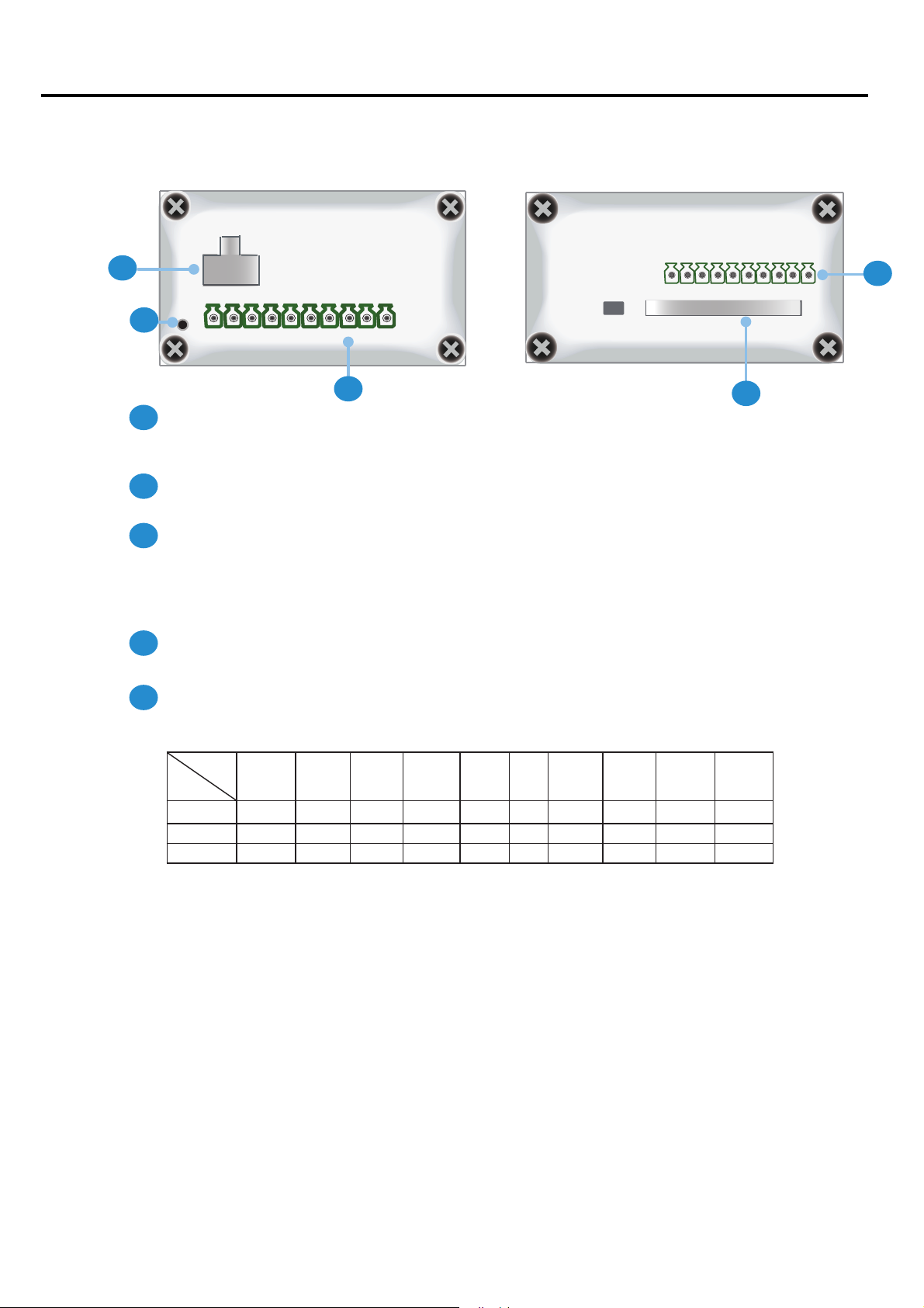
op and Bott
T
R2
anel Featur
om P
es
- +
R1
R1
R2
R3
1 2 3 4 5 6 7 8 9 10
R3
Reset Switch: A hardw
Use a pointed object to press it for 5 seconds then release it to reset the system without
turning off the power.
Power Socket
Power supply through 1x2-pin Phoenix Contact with 12~36V dual power source.
Digital Input/Output port:
The digital input/output (DIO) peripheral is provided through 10-pin terminal block
connector.
Pin 2 to 5: Digital Inputs.
Pin 7 to10: Digital Output
are reset switch
R5
R4
R4
CompactFlash Connector
One Type I / Type II CompactFlash card slot is provided.
R5
10-pin Phoenix Contact Terminal Block connector for COM5 and COM6 ports
It supports dip switch selection among RS-232, RS-422 and 485. The following table lists
the pin assignments:
COM NO.
Port Type
RS-232 GND CTS5# SOUT5 SIN5
RS-422 GND RX- RX+ TX+ TX- GND RX- RX+ TX+ TX-
RS-485 GND NC NC DATA+ DATA- GND NC NC DATA+ DATA-
Pin 1 Pin 2 Pin 3 Pin 4 Pin 5 Pin 6 PIN7 PIN 8 PIN 9 Pin10
RTS5# GND CTS6# SOUT6 SIN6 RTS6#
IMM-L30D User Manual
3

Chapter 1: Introduction
Chapter 1: Introduction
Dimensions
127mm
69.1mm
165mm
IMM-L30D User Manual
4
Chapter 2: Hardware Setup
Preparing the Hardware Installa
To access some components and perform certain service
procedures, you must perform the following procedures
first.
WARNING: To reduce the risk of personal injury,
electric shock, or damage to the equipment,
remove the power cord to remove power from the
server. The front panel Power On/Standby button
does not completely shut off system power.
Portions of the power supply and some internal
circuitry remain active until AC power is removed.
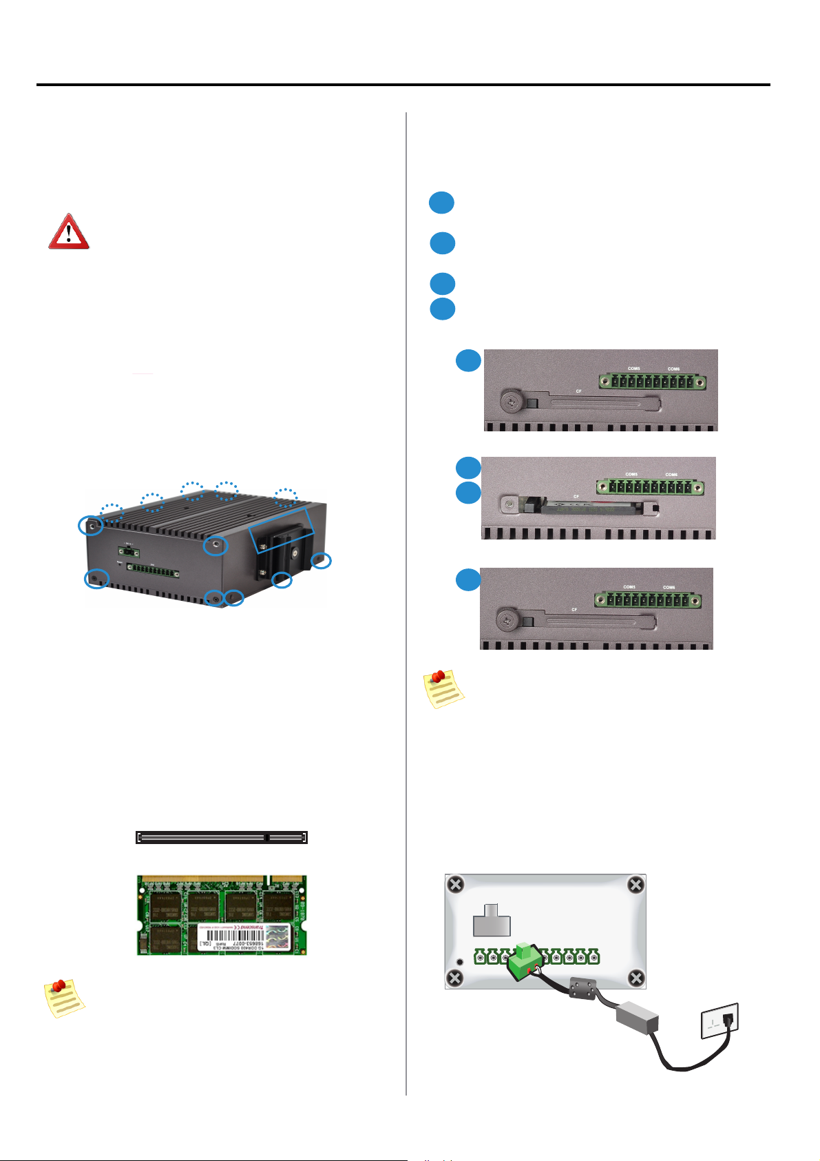
Unpower the IMM-L30D and remove the power cord.1.
The top cover has a horse shoe shape. Unscrew the 2.
3 threaded screws at the top and the bottom of the
opposite side and 2 from each side of the IMM-L30D
system.
Slide the cover backwards to open the cover 3.
upwards.
tion
Installing a C
IMM-L30D provides one C
procedures bellow for installing a CompactFlash card.
1
Unscrew the thumbscrew on the CF slot to take out
the front cover.
2
Align CompactFlash and the card slot with the arrow
on the CompactFlash pointing toward the connector.
3
Insert the CompactFlash into the connector.
Close the cover and fasten it with thumbscrew to the
4
slot.
1
2
3
ompactFlash Card
ompactFlash slot. Follow the
Installing the System Memory
The motherboard supports DDR2 memory that features
data transfer rates of 667 MHz to meet the higher
bandwidth requirements of the latest operating system
and Internet applications. It comes with one Double Data
Rate(DDR2) Small Outline Dual Inline Memory Module
(SO-DIMM) socket.
Align the memory module’s cutout with the SO-DIMM 1.
socket’s notch.
Install the SO-DIMM.2.
Notch
Cutout
4
Note: The device has an error proof design so that
it can’t be inserted if it is in the wrong orientation
You should insert the CF card with its cutout facing
up and arrow on the CompactFlash pointing
toward the connector
onnec
C
Connect the IMM-L30D to a 12~36 VDC pow
power source comes from an AC/DC Adapter through a
Phoenix contact.
ting Pow
-
+
er
er source. The
IMM-L30D User Manual
Note:
SO-DIMMs installed should meet the requir
1.
speed which is 667 MHz. Do not install SO-DIMM
supporting differ
2.
The motherboard supports a maximum memory
capacity of 2GB.
ent speeds.
ed
5
Chapter 3: Motherboard Information
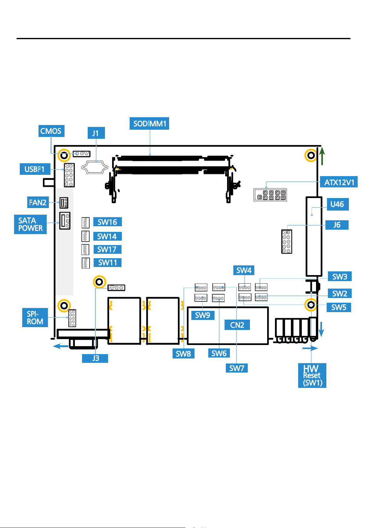
Motherboar
The motherboard la
the pin assignments and the internal connectors
d Lay
out
yout shows the connectors and jumpers on the board Refer to the following picture as a reference of
159mm
114mm
IMM-L30D User Manual
6
Chapter 3: Motherboard Information
Jumper Settings
SATA (J1):
The system supports one SAT
1 2 3 4 5 6 7
A II drive
Pin No. Function
1 GND
2 TX_P
3 TX_M
4 GND
5 RX_M
6 RX_P
7 GND
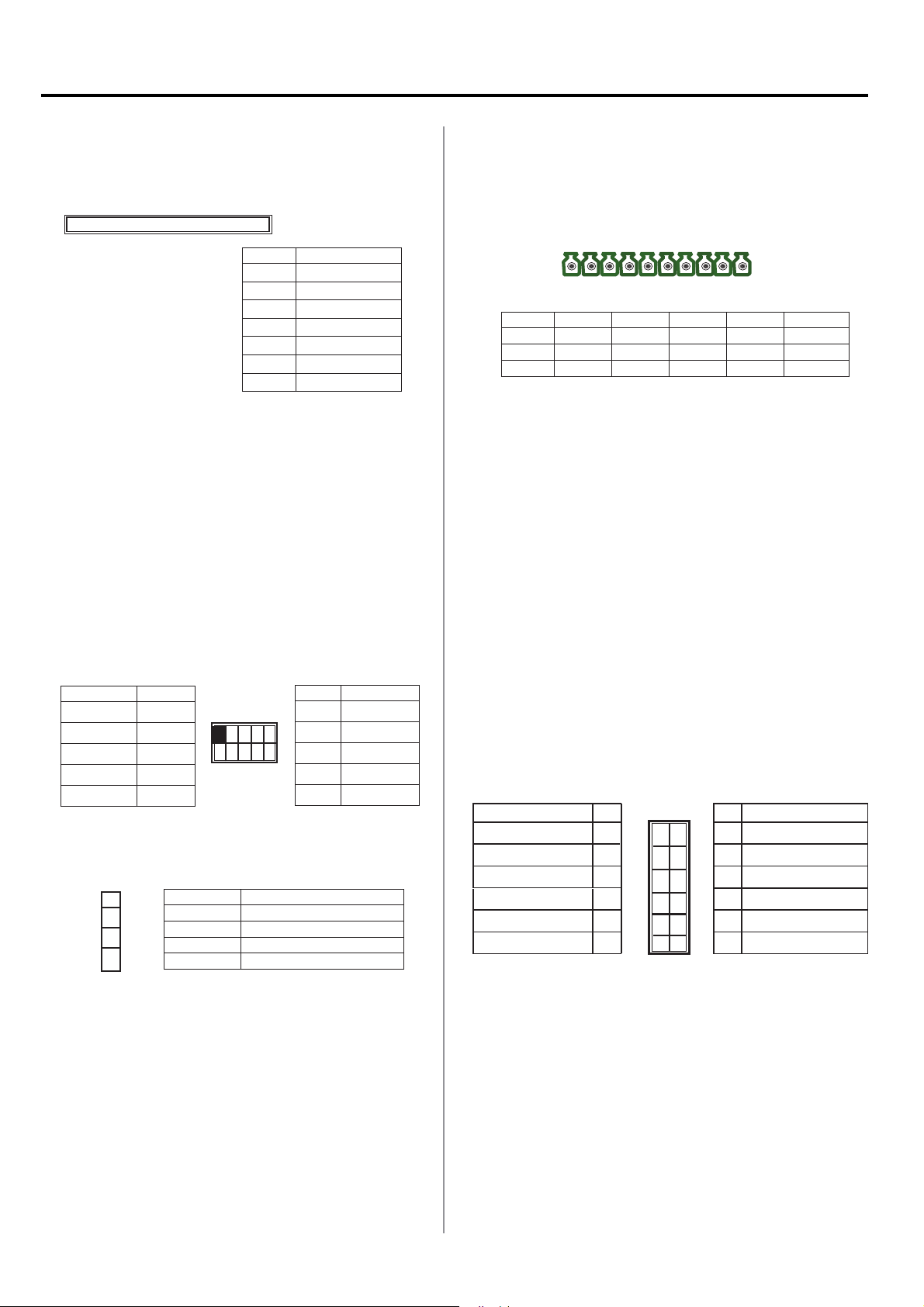
U46:
outputs The connector type of IMM-L30D is plug-in screw
terminal block that enables you to connect to field I/O
devices directly.
Pin No. 1 2 3 4 5
Function
Function GND F_GPO0 F_GPO1 F_GPO2 F_GPO3
Digital Inputs Requirements
Digital Input/Output Requirements
This connector provides 4 digital inputs and 4 digital
1
GND FP_DI_0 FP_DI_1 FP_DI_2 FP_DI_3
Pn No. 6 7 8 9 10
8 9
102 3 4 5 6 7
SODIMM1
SODIMM1: The SO-DIMM socket is used to connect the
DDR2 667 (200 pin) memory. The system can suport up to
2 GB in maximum.
ATX12V1:
The system is designed to operate with a single
DC input with voltage range from +12 to 36V. And it is
supplied through the Phoenix Contact. This connector is
provided for the main board to receive power from the
input source.
10
Function
2
4
6
8
12V
12V
12V
12V
12V
Function Pin No.
NC 1
GND 3
GND 5
GND 7
GND
9
1 3 5 7 9
2 4 6 8 10
Pin No.
4 Pin SATA Power Connector.SATA Power (J5):
4
3
2
1
Pin No. Function
1 5V
2 Ground
3 Ground
4 12V
Input /Output Voltage:
Logic 0: 0 ~ 2V DC
Logic 1: 2 ~ 5V DC
Current limit: Maximum 100mA for each pin
VGA Connector (J6): The system has an integrated
graphics processing unit (GPU) from Intel’s Graphics Media
Accelerator. It has the following features:
A D-sub 15-pin connector to support a VGA CRT •
monitor. It supports resolutions up to 1920 x 1080.
Intel Dynamic Video Memory Technology 4.0•
Intel Clear Video Technology consisted of MPEG2 •
Hardware Acceleration and ProcAmp.
Pin Name Pin
R 1
G 3
B 5
H-SYNC 7
V-SYNC
Detect-display Data 11
1
3
5
7
9
9
11
Pin Pin Name
2 GND
2
4 GND
4
6 GND
6
8 GND
8
10
10
12 Detect-display Clock
12
GND
IMM-L30D User Manual
7

Chapter 3: Motherboard Information
SW3/SW4/SW7/SW8/SW16/SW17: Switches SW3, SW4,
SW7, SW8, SW16, and SW17 are used to set the serial
port type of COM, COM2, COM3, COM4, COM5 and COM6
respectively. Use the table below for the settings of the
switches for COM1 through COM6.
12 3 4
ON
OFF
SW3, 4, 7, 8
ONOFF
SW16
ON OFF
1
2
3
4
4
3
2
1
SW17
SW2/SW5/SW6/SW9/SW11/SW14: Switches SW2, SW5,
SW6, SW9, SW11, and SW14 are used to enable or disable
the signal termination for COM1, COM2, COM3, COM4,
COM5, and COM6 respectively. Look at the last of the table
of the table below for the DIP switch settings for COM1
through COM6.
We strongly recommend that you disable termination when
the port is configured for RS-232 and enable it when the
port is configured for RS-422/RS-485.
ONOFF
SW11/SW14
Switch 7:
1 ON
2 OFF
3 OFF
4 OFF
Switch 7:
1 OFF
2 ON
3 ON
4 OFF
Switch 7:
1 OFF
2 ON
3 OFF
4 ON
Switch 6:
Enable ON
1 ON
2 ON
3 ON
4 ON
Disable OFF
1
2
3
4
Switch 8:
1 ON
2 OFF
3 OFF
4 OFF
Switch 8:
1 OFF
2 ON
3 ON
4 OFF
Switch 8:
1 OFF
2 ON
3 OFF
4 ON
Switch 9:
Enable ON
1 ON
2 ON
3 ON
4 ON
Disable OFF
Switch 16:
1 ON
2 OFF
3 OFF
4 OFF
Switch 16:
1 OFF
2 ON
3 ON
4 OFF
Switch 16:
1 OFF
2 ON
3 OFF
4 ON
Switch 11:
Enable ON
1 ON
2 ON
3 ON
4 ON
Disable OFF
Switch 17:
1 ON
2 OFF
3 OFF
4 OFF
Switch 17:
1 OFF
2 ON
3 ON
4 OFF
Switch 17:
1 OFF
2 ON
3 OFF
4 ON
Switch 14:
Enable ON
1 ON
2 ON
3 ON
4 ON
Disable OFF
Port
Type
RS-232
RS-422
RS-485
(Enable/disable)
Termination
12 3 4
ON
OFF
SW2, 5, 6, 9
COM 1 COM 2 COM 3 COM 4 COM 5 COM 6
Switch 3:
1 ON
2 OFF
3 OFF
4 OFF
Switch 3:
1 OFF
2 ON
3 ON
4 OFF
Switch 3:
1 OFF
2 ON
3 OFF
4 ON
Switch 2:
Enable ON
1 ON
2 ON
3 ON
4 ON
Disable OFF
Switch 4:
1 ON
2 OFF
3 OFF
4 OFF
Switch 4:
1 OFF
2 ON
3 ON
4 OFF
Switch 4:
1 OFF
2 ON
3 OFF
4 ON
Switch 5:
Enable ON
1 ON
2 ON
3 ON
4 ON
Disable OFF
Clear CMOS (JP1):
The motherboard contains a jumper
that can erase CMOS data and resets the systemBIOS
information. Normally this jumper should be set with
pins 1-2 closed. If you want to reset the CMOS data, set
this jumper to 2-3 closed for just a few seconds, and then
move the jumper back to 1-2 closed. This procedure will
reset the CMOS to its default setting.
3 2 1
Pin No. Function
Short 1-2 Normal (Default)
2-3 Clear CMOS
SPI-ROM(J2): Using the appropriate cable to connect this
10-pin ISP in header connector, the user can update the
SPI Flash soldered on board
Function Pin No.
SPI_HOLD_N 1
SPI_CS0_N 3
SPI_MISO 5
RSVD 7
GND 9
1
3
5
7
9
Pin No. Function
2
2 RSVD
4
4 VCC3P3_SB_SPI
6
6 RSVD
8
8 SPI_CLK
10
10 SPI_MOSI
CN2: Connector CN2 together with U79 provide access to
the COM1 through COM6 serial port’s data transmission
when the port is configured for either RS-422/RS-485
or RS-232 serial protocol. The signals present on each
of the connector’s pins for these three modes can be
referenced in Front Panel Features, Chapter 1 Introduction.
The COM ports' serial protocol mode is configured using
the following dip switches: SW3, SW4, SW7, SW8, SW16,
and SW17. In addition, when used as in RS-485 mode, the
system can automatically detect the direction of incoming
data and switches its transmission direction accordingly
– the automatic data flow control in RS-485. Hence, no
handshaking signal (RTS signal) is necessary. This allows
you to conveniently build an RS-485 network with just two
wires. More significantly, application software previously
written for half duplex RS-232 environments can be
maintained without modification.
USBF1: Dual USB Interface Connector . It is used for
connecting the USB module cable. It complies with USB2.0
and support up to 480 Mbps connection speed.
Pin Name Pin No.
USB_VCC 1
Key 3
USBD0- 5
USBD0+ 7
GND 9
1
3
5
7
9
Pin No. Pin Name
2
4
6
8
10
2 GND
4 USBD1+
6 USBD1-
8 Key
10
USB_VCC
IMM-L30D User Manual
System Management Bus (J3):
1 2 3
Pin No. Function
1 ICH_SMBDAT
2 Ground
3 ICH_SMBCLK
8
 Loading...