

Indumicro IMM-A22S User Manual
User
IMM-A2
Mobile / Bo
Manual
S
2
x Computer

___________________________________
___________________________________
Warning!
This equipment generates, uses and can radiate radio frequency ener
used in accordance with the instructions manual may cause interference to radio communications.
It has been tested and found to comply with the limits for a Class A computing device pursuant to
FCC Rules, which are designed to provide reasonable protection against such interference when
operated in a commercial environment. Operation of this equipment in a residential area is likely
to cause interference in which case the user at his own expense will be required to take whatever
measures may be required to correct the interference.
Electric Shock Hazard – Do not operate the machine with its back cover removed. There are
dangerous high voltages inside.
gy and if not installed and
Disclaim
This information in this document is subject to change wi
Indumicro.com be liable for damages of any kind, whether incidental or consequential,
arising from either the use or misuse of information in this document or in any related
materials.
er
thout notice. In no event shall

Chapter
Table of Contents
1:
Getting Started
1.1 Features ………………………
1.2 Specifications …………………………………………………………………………… 1
1.3 Dimensions ……………………………………………………………………………… 2
1.4 Brief Description of the IMM-A22S
1.5 R
Chapter 2:
2.1 Operations after
2.2 BIOS Setup Utility ……………………………………………………………………… 7
2.3 System Overview ……………………………………………………………………… 8
2.4 Advanced Settings …………………………………………………………………… 9
2.5 Advanced PCI/PnP Settings ………………………………………………………… 18
2.6 Boot Settings …………………………………………………………………………… 21
2.7 Security Settings ……………………………………………………………………… 23
eplacing the hard disk
BIOS Setup
………………………………………………………… 1
…
…………
…………………………
POST Screen ……………………………………………………… 5
……………………………………… 3
……………………………………… 4
2.8 Advanced Chipset Settings …………………………………………………………… 25
2.9 Exit Options …………………………………………………………………………… 29

Chapter 1: Getting Started
1.1
Features
Fanless
design
Slim size
All solid capacitor motherboard
Wide range DC 11~32V power input
Specifications
1.2
M
odel No.
Specs
CPU
Chi
pset
System Memory
Storage support .5" SATA HDD tray
External
I/O Port
Atom D
Intel
Intel ICH
1 x 20
1 x 2
1 x CF slot On board (external)
Rear:
4 x USB 2.0 connector (rear)
2 x RJ-45 LAN connector
1 x DB-9 RS232 (COM1)
1 x DB-15 VGA
4
525 1.8GHz dual core pr
8M
chipset
Pin SO-DIMM DDR3 800MHz, up to 2GB
IMM-A2
ocessor FSB
2S
800MHz
Ex
pansion Slot
Power Input
OS support
Con
struction
Color
Mounting
Dimensions
Net Weight
Operating Temperature
Storage Temperature
Storage Humidity
Certificate
Front:
x DB-9 RS-232 (COM2)
1
1 x DB-9 RS-232/422/485 (COM3), default RS-485
None
DC 11~32V
Windows XP, Windows XP Pro, XP Embedded, Windows Embedded
Standard 7
Aluminum molding heat sink and heavy duty steel chassis
Blue heatsink / Black chassis
Wall Mount
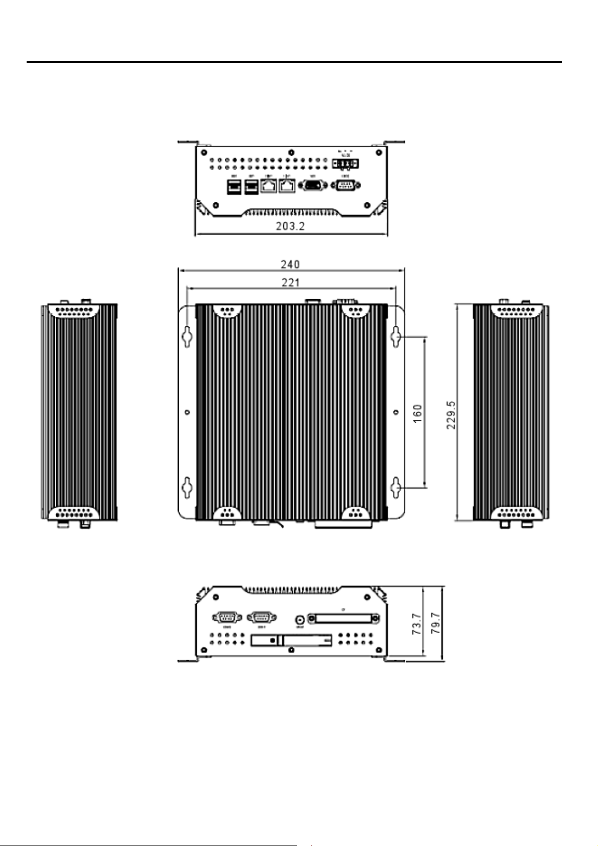
229.5(W) x 203.2(D) x 79.9(H) mm
2kgs
0~50゚C
-20~60゚C
10~90% @40゚C non-condensing
CE/FCC Class A
MM-A22S User Manual
I
1
Chapter 1: Getting Started
1.3 Dimensions
MM-A22S User Manual
I
Dimensions of the
IMM-A22S
2
Chapter 1: Getting Started
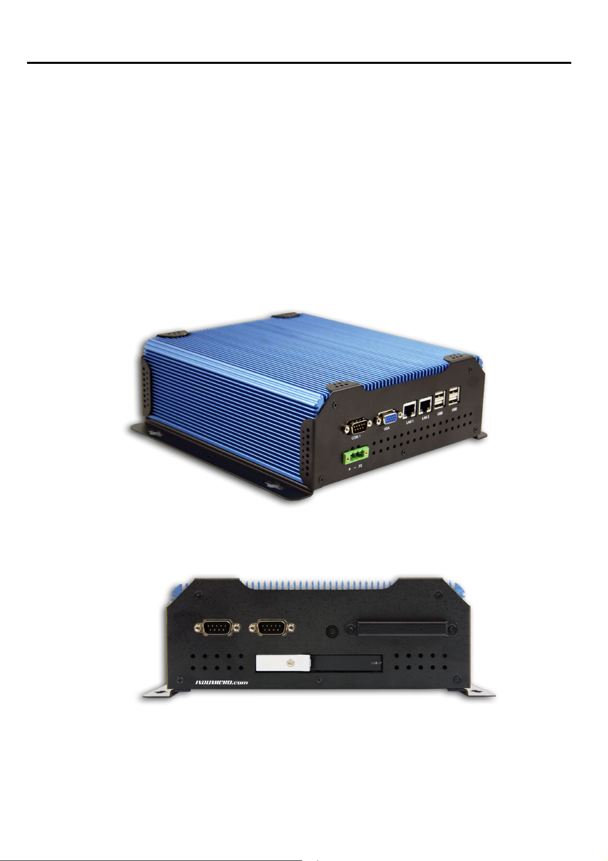
1.4 Brief Description of the
The IMM-A22S is a robust cost-effective embedded Box PC. It is powered by an Intel Atom™ D525
1.8GHz dual core processor with an 800MHz Front Side Bus.
system offers 4 USB 2.0 ports, 2 x Gigabit LAN, 3 x COM Ports, 1 x VGA, an easy accesible
The
2.5” HDD and and an external CompactFlash slot.
It is ideal for kiosks, POS systems, airport terminal controllers, digital entertainment, and factory
automation from small visual interface and maintenance applications to large control process
applications.
The system comes with a DC11~32V wide-ranging power input.
IMM-A22S
IMM-A22
S User Manual
3
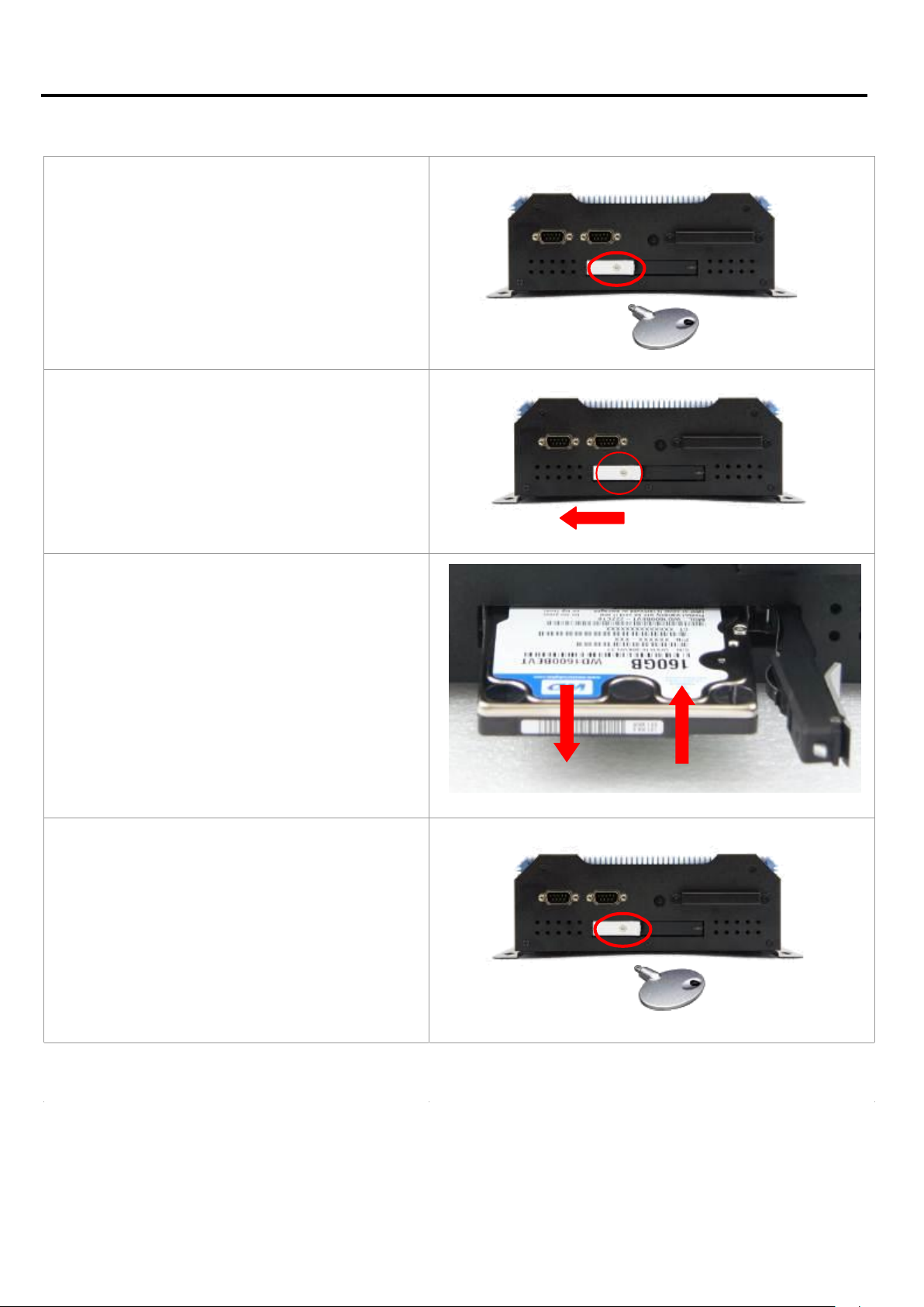
S t
e p 1
Unlock the door of the drive bay with the key
that comes with the system.
S t
e p 2
Pul
l the handle to unlock the door of the
dr
ive bay
.
S t
e p 3
Pu
l
l out or push in the hard disk
.
S t
e p 4
Press the handle in position and lock the
drive bay door with the key.
Chapter 1: Getting Started
1.5 Replacing the hard disk
IMM-A22S User Manual
4
Chapter 2: BIOS
Setup
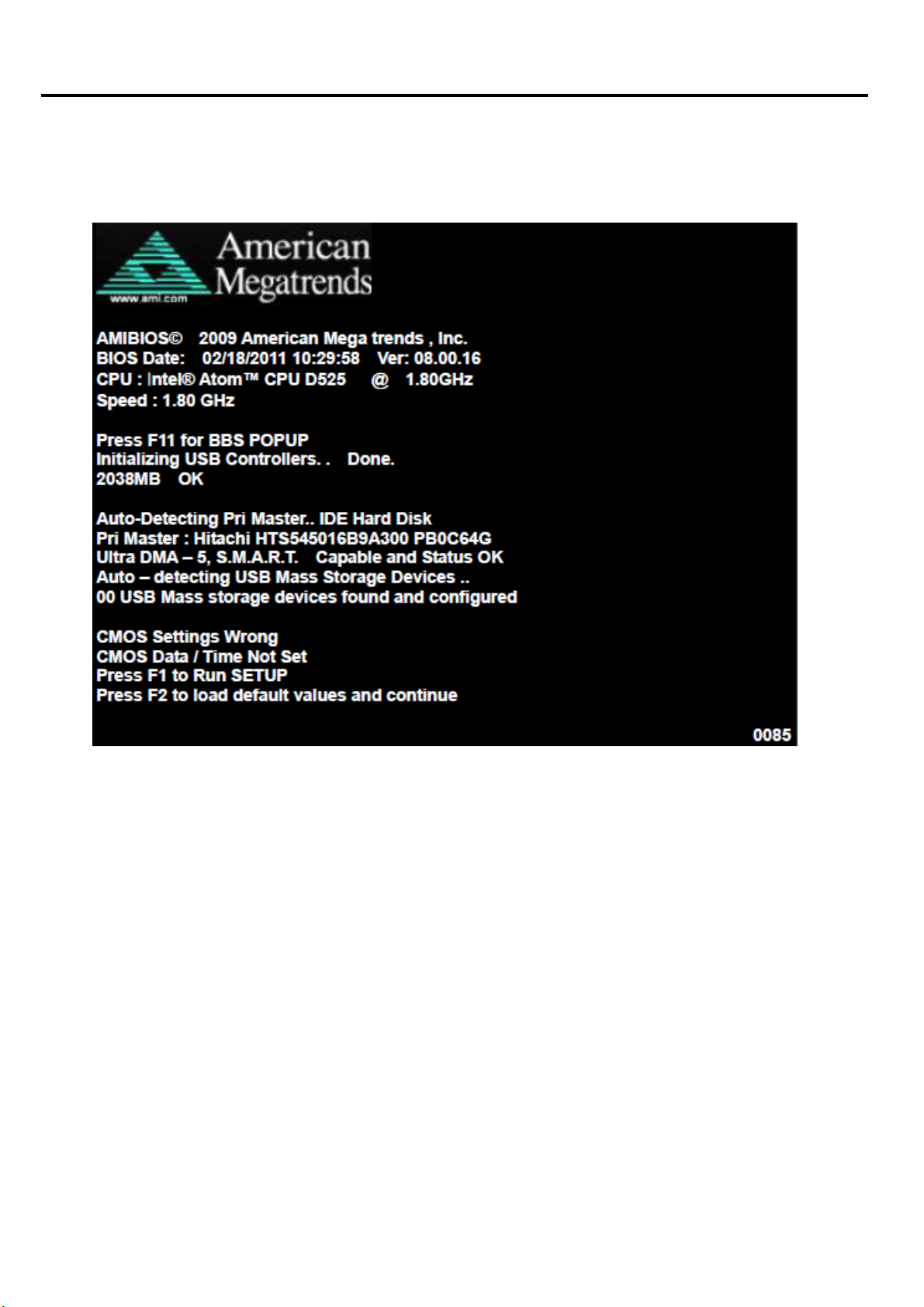
2.1 Operations after POST Screen
After CMOS discharge or BIOS flashing operation, the system will display the following
screen for your further operation. Press F2 key to continue or F1 key to enter CMOS Setup.
MM-A22S User Manual
I
5
Chapter 2: BIOS
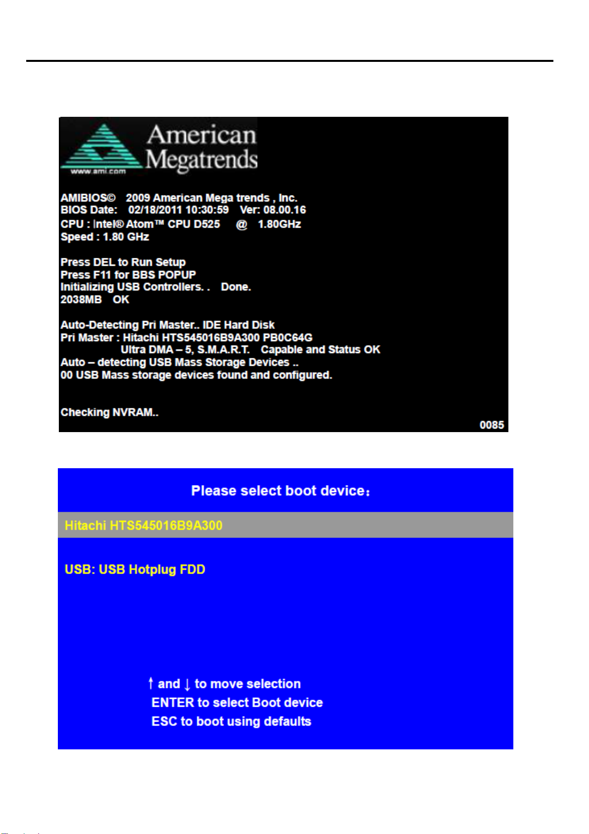
optimizing and exiting CMOS Setup, the POST screen displayed for the first time is as
After
follows and includes basic information on BIOS, CPU, memory, and storage devices.
Setup
Press F11 key to enter Boot Menu during POST, as show by the following figure.
MM-A22S User Manual
I
6
Chapter 2: BIOS
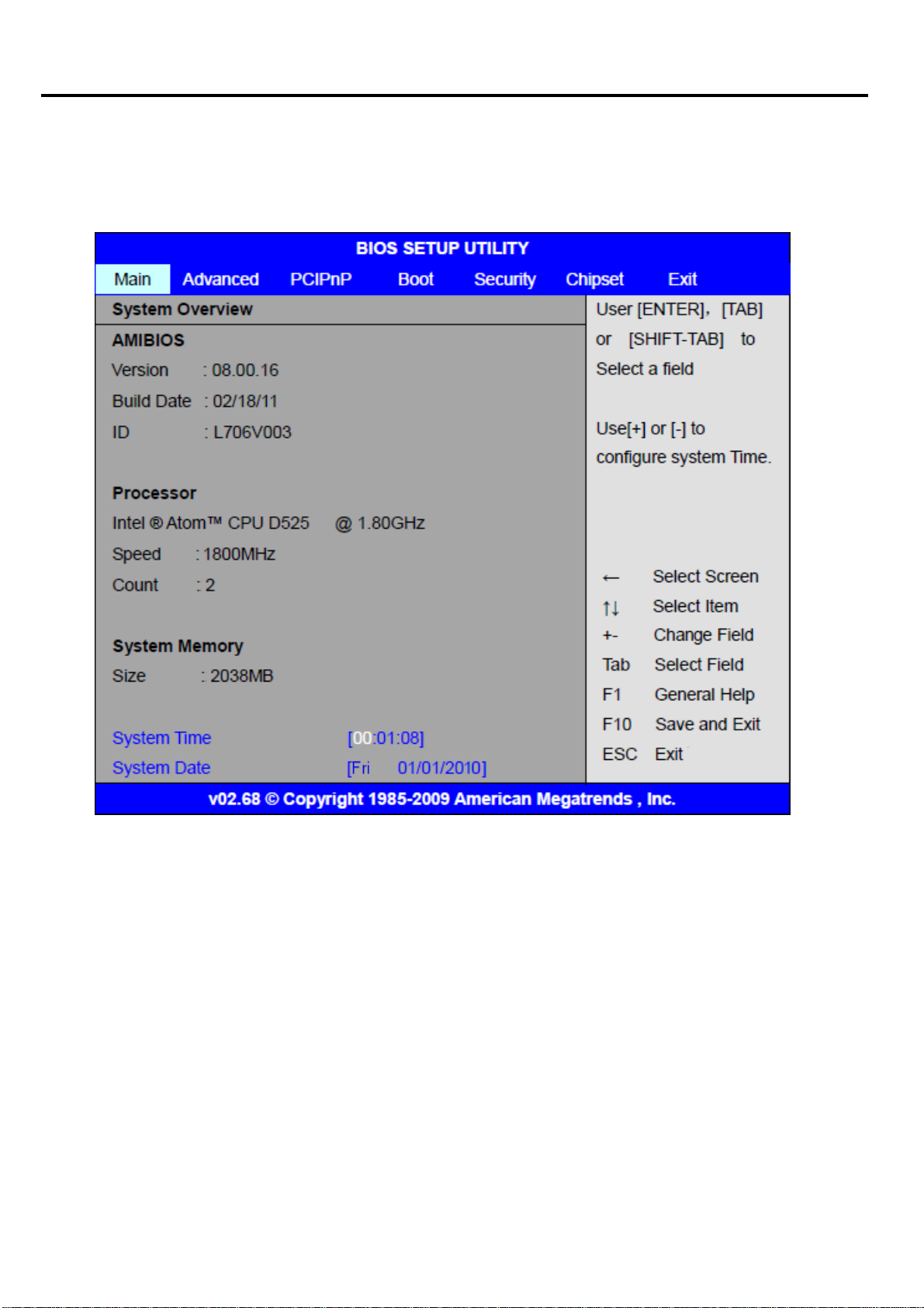
2.2
BIOS Setup Utility
Press [Del] key to enter BIOS Setup utility during POST, and then a main menu containing
system summary information will appear.
Setup
MM-A22S User Manual
I
7

Chapter 2: BIOS
System Overview
2.2
Setup
System
Hour: 0 to 23
System date:
Time:
Set the system time, the time format is:
Minute: 0 to 59
Second: 0 to 59
Set the system date, the date format is:
Day: Note that ‘Day’ automatically changes when you set the date.
Month: 0 to 12
Date: 0 to 31
Year: 2010 to 2099
MM-A22S User Manual
I
8
Chapter 2: BIOS
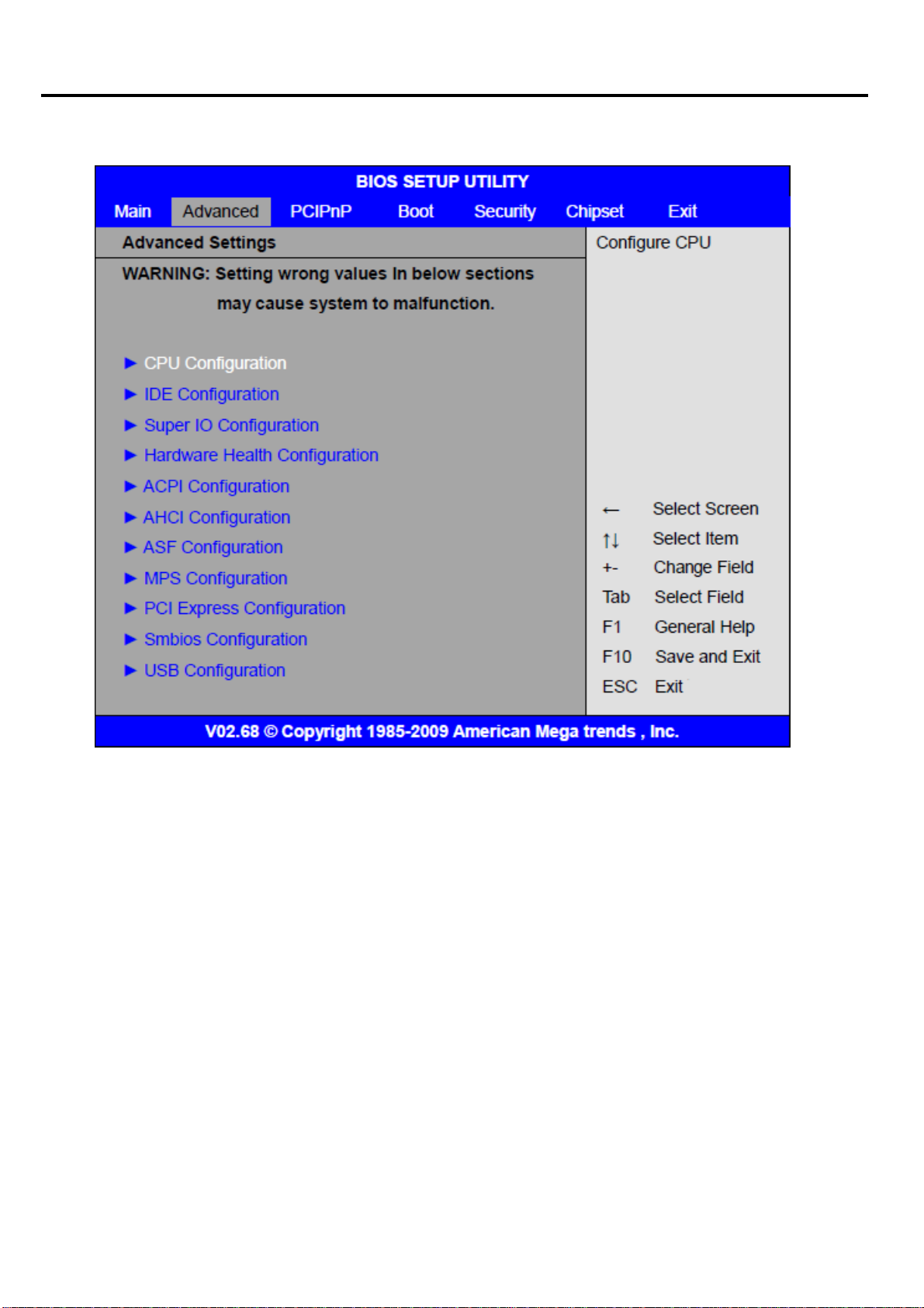
Advanced Settings
2.4
Setup
MM-A22S User Manual
I
9
 Loading...