

Indumicro IMM-A21S, IMM-A21P2S, IMM-A21PS User Manual
IMM-A21S / A21PS / A21P2S
Mobile / Box Computer
User
Manual

___________________________________
___________________________________
Warning!
This equipm
used in accordance with the instructions manual may cause interference to radio communications.
It has been tested and found to comply with the limits for a Class A computing device pursuant to
FCC Rules, which are designed to provide reasonable protection against such interference when
operated in a commercial environment. Operation of this equipment in a residential area is likely
to cause interference in which case the user at his own expense will be required to take whatever
measures may be required to correct the interference.
Electric Shock Hazard – Do not operate the machine with its back cover removed. There are
dangerous high voltages inside.
ent generates, uses and can radiate radio frequency energy and if not installed and
Disclaim
This information in this document is subject to change w
Indumicro.com be liable for damages of any kind, whether incidental or consequential,
arising from either the use or misuse of information in this document or in any related
materials.
er
ithout notice. In no event shall

Table of Contents
Chapter 1: Getting Started
1.2 Specifications…………………………………………………………………………..1
1.3 Dimensions…………………………………………………………………………….2
1.4 Brief Description of the IMM-A21S/A21PS/A21P2S………………………………5
1.5 Safety Precautions…………………………………………………………………….5
1.1 Feat
Chapter 2: Hardware Installation
2.2 APO/ATX Power Mode Selection…..………………………………………………..7
2.1 Installi
Chapter 3: BIOS Setup
3.3 BIOS Menu Screen.………………………………………………………………….11
3.3.1 Standard CMOS Features.……………………………………………………….12
3.3.2 Advanced CMOS Features.……………...……………………………………….14
3.3.3 Advanced Chipset Features.……………...………..…………………………….19
3.3.4 Integrated Peripherals……...……………...………..…………………………….21
3.3.5 Security Chip Configuration.……………...………..…………………………….26
3.3.6 Power Management Setup...……………...………..…………………………….27
3.3.7 PnP/PCI Configurations…...……………...………..…………………………….29
3.3.8 PC Health Status…………...……………...………..…………………………….30
3.3.9 Frequency/Voltage Control..……………...………..…………………………….31
3.3.10 Load Optimized Defaults..……………...………..………………………..…….32
3.3.11 Set Supervisor Password..……………...………..………………………..……33
3.3.12 Set User Password……….……………...………..………………………..……34
3.3.13 Save & Exit Setup.……….……………...………..………………………..……35
3.3.14 Exit Without Saving...…….……………...………..………………………..……36
3.1 Managing and Updating your BIOS...……………………..………………………..8
3.2 BIOS Setup Program..………………………………………………………………..9
ures………………………………………………………………………………..1
ng PCI Add-on Cards...………………………………………………………..6

Chapter 1: Getting Started
1.1 Features
o
Supports Intel® FCBGA8 45nm Atom™ N270 Processor 533 MHz
o
Intel® 945GSE + ICH7-M Chipset
o
Fanless design
o
1 x DDR2 SO-DIMM Socket, Support DDR2 533 up to 2GB
o
2 x 10/100 Ethernet LAN, 1 x VGA connector
o
3 x COM ports & 4 x USB ports
o
1 x 2.5” HDD space & 1 x CF External Slot
o
Support 11~32V/DC Input, support AT/ATX mode
1.2 Specifications
Model
Specs
CPU
Chipset
stem Me
Sy
Storage support
Keyboard & Mouse
Serial Port
Ethernet
USB Po
Audio
Expansion Slot
Power Input
Watchdog Timer
mor
VGA
DVI
rt
No.
y
s
IMM-A21PS
IMM-A21PS
IMM-A22P2S
Supports Intel® FCBGA8 45nm Atom™ N270 Processor 533 MHz
Intel® 945GSE + ICH7-M Chipset
1 x DDR2 SO-DIMM Socket, Support DDR2 533 up to 2GB
1 x 2.5” SATA HDD space and 1 x External CF Slot
1x VGA port
1 x 24pin DVI port
2 x PS/2 for Keyboard and Mouse Connectors
2 x RS-232
2 x Gigabit LAN
4 x USB port on the I/O side and 2 x USB on the front side
1 x Line-in, 1 x Line-out, 1 x MIC in
None 1 x PCI slot 2 x PCI slots
DC 11~32V
Reset: 1 sec.~255 min. and 1 sec. or 1 min./step
OS support
Construction
Color
Mounting
Dimensions (WxHxD)
Net Weight
Operating Temperatu
Storage Temperature
Relative Humidity
Certificate
IMM-A21[Px]S User Manual
re
XP Pro, XP Embedded, Vista, 7
Aluminum Molding & Heavy-duty steel chassis
Blue Heat sink and Black Chassis
Wall mount
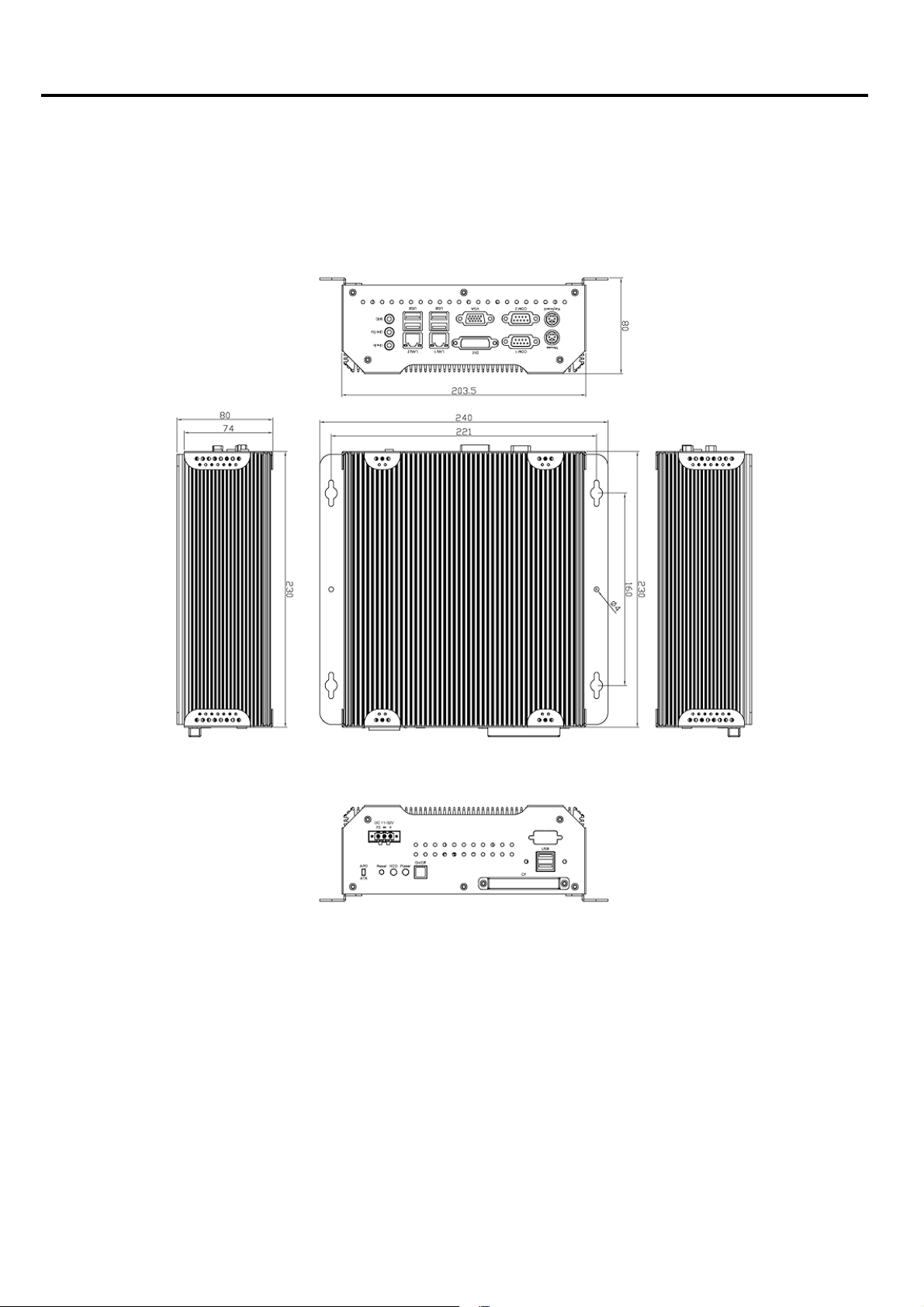
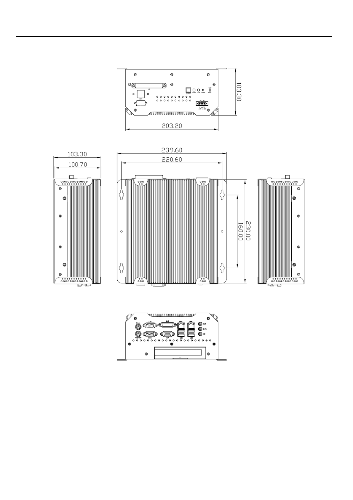
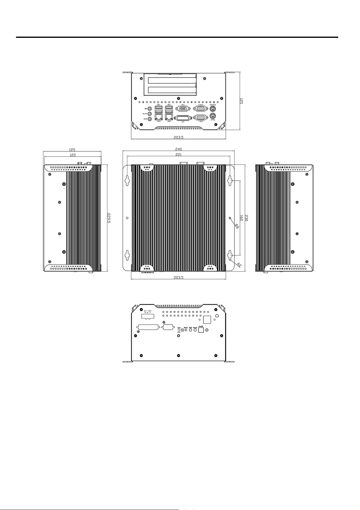
203.5 x 230 x 80 mm 203.5 x 230 x 103.3 mm 203.5 x 230 x 125 mm
4.5kgs 4.5kgs 5kgs
゚C
0~50
-20~60
゚C
10%~95% (non-condensing)
Meet CE / FCC Class A
1
Chapter 1: Getting Started
1.3 Dimensions
IMM-A21[Px]S User Manual
Dimensions of the IMM-A21S
2
Chapter 1: Getting Started
IMM-A21[Px]S User Manual
Dimensions of the IMM-A21PS
3
Chapter 1: Getting Started
IMM-A21[Px]S User Manual
Dimensions of the
IMM-A21P2S
4
Chapter 1: Getting Started
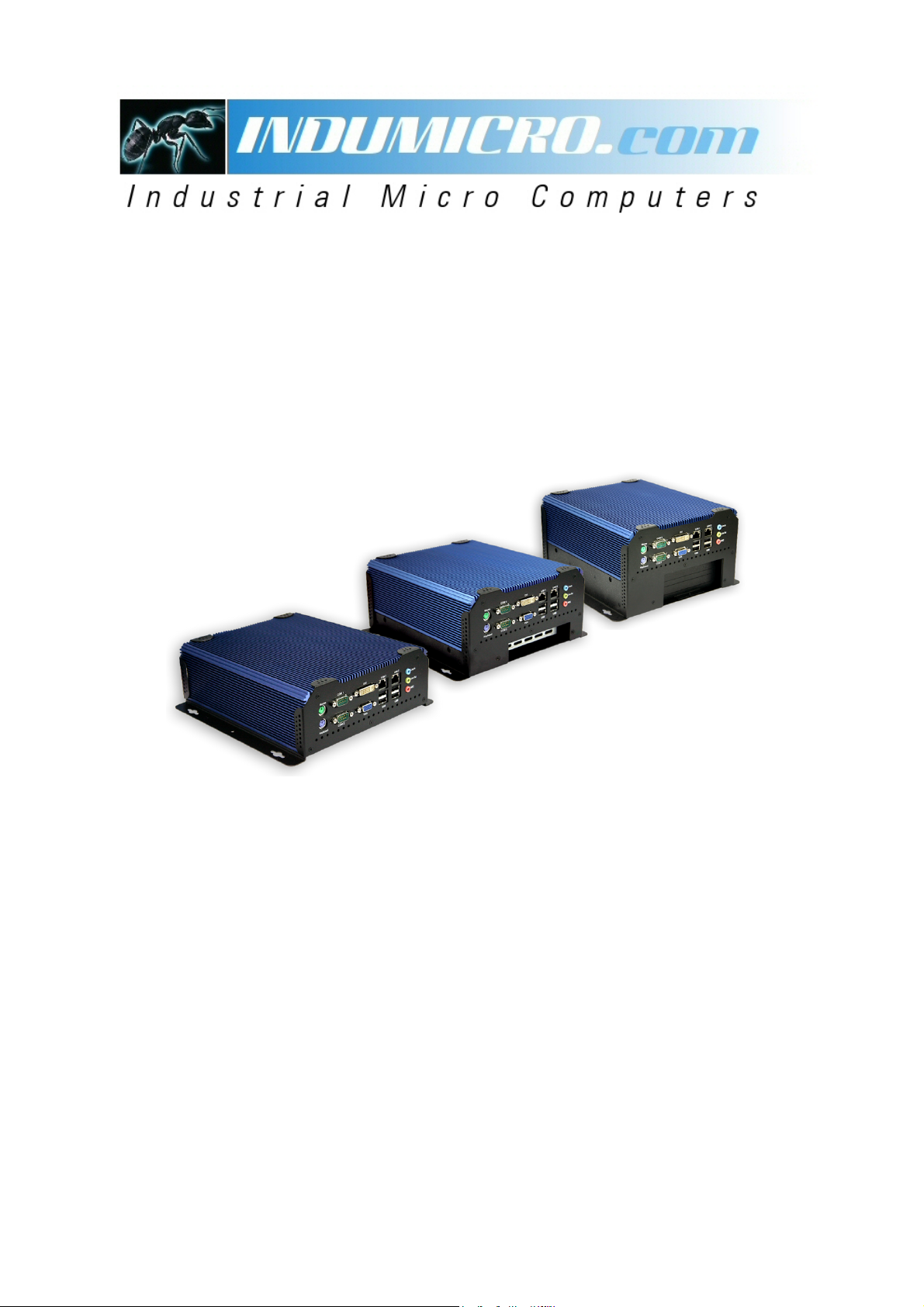
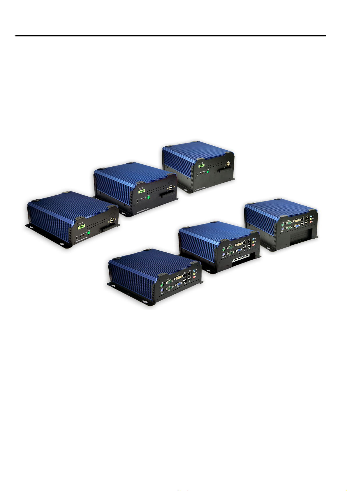
1.4 Brief Description of the IMM-A21S/A21PS/A21P2S
The IMM-A21S/A21PS/A21P2S are robust cost-effective embedded Box PCs. They are powered
by an Intel Atom™ N270 1.6GHz processor, implemented in 45nm technology. These systems offer
6 USB 2.0 ports, 2 x Gigabit LAN, 2 x COM Ports, 1 x VGA, 1 x DVI, Audio Input/Output, 1 x PCI slot
(IMM-A21PS) or 2x PCI slots ( IMM-A21P2S), 1 x SATA HDD and 1 x external CF slot. They are ideal
for kiosks, POS systems, airport terminal controllers, digital entertainment, and factory automation
from small visual interface and maintenance applications to large control process applications.
These systems come with a DC11~32V wide-ranging power input.
Front and Rear View of the IMM-A21PxS
1.5 Safety Precautions
Follow the messages below to avoid your systems from damage:
o
Avoid your system from static electricity on all occasions.
o
Prevent electric shock. Don‘t touch any component
o
Always disconnect power when the system is not in use.
o
Disconnect power when you change any hardware devices. For instance, when you connect
a jumper or inst all any cards, a surge of power may damage the electronic components or
the whole system.
s of this card when the card is power-on.
IMM-A21[Px]S User Manual
5

Chapter 2: Hardware Installation
2.1 Installing PCI Add-on Cards
2.1.1 Removing bottom cover
Use screwdriver to remove the bottom cover 27 screws.
Keep them safely for later use.
2.1.2 Support 1 x PCI slot (IMM-A21PS only)
Support 2 x PCI slots (IMM-A21P2S only
Shown in the picture are the one PCI expansion slots for
addon. The location of the 1 x PCI expansion slot card is
found by the side of the rail.
)
2.1.3 Insert the PCI Card
Now slide an addon into the slot of the PCI as circled in
the picture and making sure the golden p
evenly aligned with the slot of the PCI. Then carefully
push the card deep into the slot.
2.1.4 Tightening PCI bracket
Now get the addon secured by tightening the screw as
circled in the picture.
** Support Card size of PCI : 115 mm x 210mm
art of the card is
2.1.5 Finish the installation
To finish the job, get the 27 screws tightened onto the
chassis as shown in the picture.
IMM-A21[Px]S User Manual
6
Chapter 2: Hardware Installation
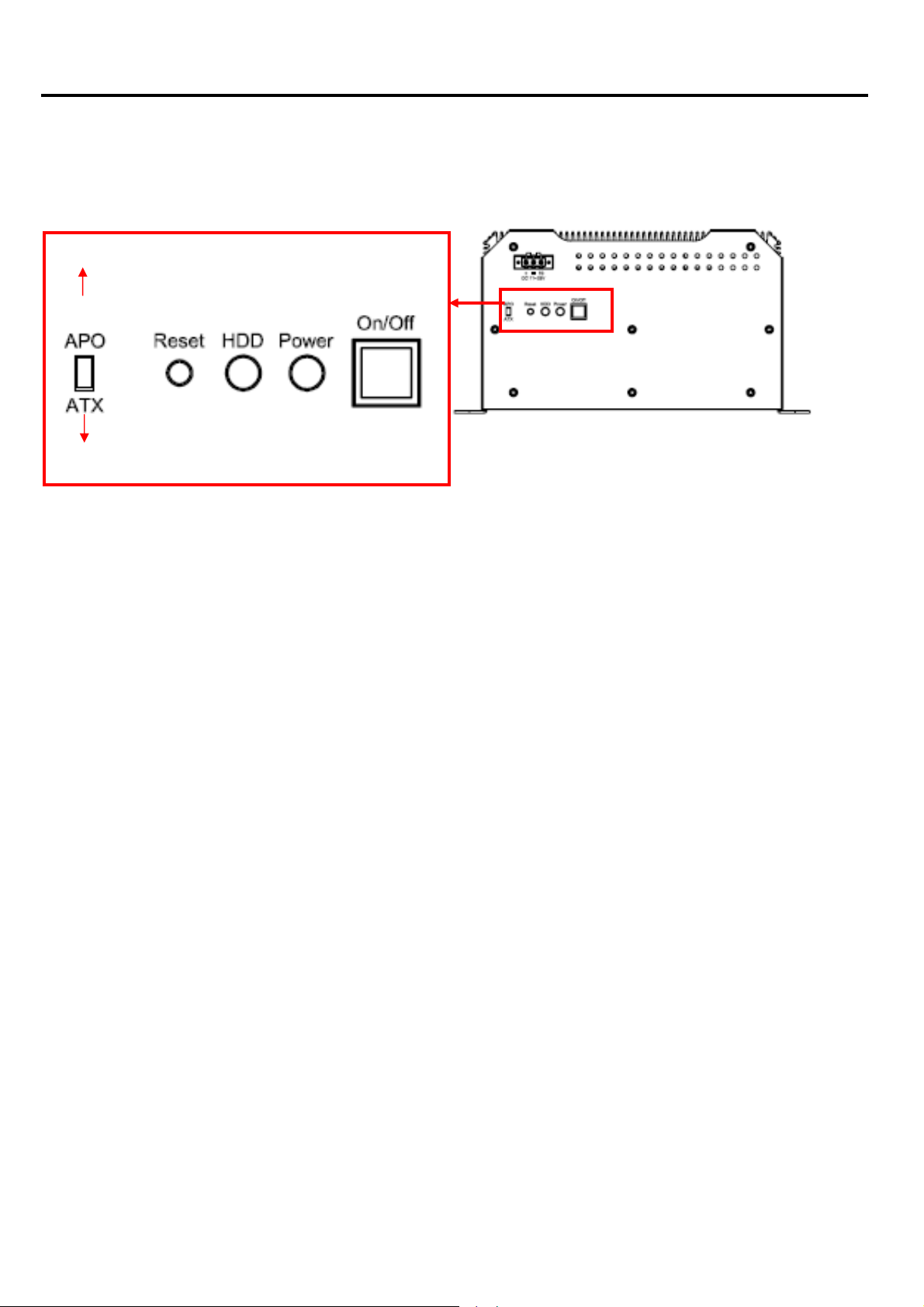
2.2
APO/A
APO and ATX power modes can be used on these Box PCs. Power mode flexibility allows you to
select the most suitable power mode for your unique application requirements. (Default: APO)
APO Mode (Auto Power On)
TX Power Mode Selection
ATX Mode
IMM-A21[Px]S User Manual
7

Chapter 3: BIOS Setup
3.1 Managing and Updating your BIOS
3.1.1 Creating a bootable floppy disk
1. Do either one of the following to create a boot
DOS environment
a. Insert a 1.44MB floppy disk into the dirve.
b. At the DOS
Windows® XP, V ista, 7 environment
a. Insert a 1.44 MB floppy disk to the floppy disk drive.
b. Click St
c.
Select the 3 1/2 Floppy Drive icon.
d. Click File from the menu, then select Format
A Format 3 1/2 Floppy Disk window appears.
e. Select Create an MS-DOS startup disk from the format options field, then click Start.
Windows® 2000 environment
Insert a formatted, high density 1.44 MB floppy disk into the drive.
a.
b. Insert the Windows® 2000 CD to the optical drive.
c. Click Start, then select Run
prompt, type format A:/S then press <Enter>.
art from the Windows® desktop, then select My Computer.
able floppy disk.
From the Open
D:\bootdisk\makeboot a:
Copy the original or the latest motherboard BIOS file to the bootable floppy disk.
2.
assuming that D: is your optical drive.
d. Press <Enter>, then follow screen instructions to continue.
field, type:
IMM-A21[Px]S User Manual
8

Chapter 3: BIOS Setup
3.2 BIOS Setup Program
This motherboard supports a programmable firmware chip that you can update using the provided
utility described in section “3
Use the BIOS Setup program when you are installing a motherboard, reconfiguring your system,
or prompted to “Run Setup”. This section explains how to configure your system using this utility.
Even if you are not prompted to use the Setup program, you can change the configuration of your
computer in the future. For example, you can enable the security password feature or change the
power management settings. This requires you to reconfigure your system using the BIOS Setup
program so that the computer can recognize these changes and record them i n the CMOS RAM
of the firmware hub.
The firmware hub on the motherboard stores the Setup utility . When you start up the computer ,
the system provides you with the opportunity to run this program.
Press <Del> during the Power-On-Self-Test (POST) to enter the Setup utility; otherwise, POST
continues with its test routines.
.1 Managing and updating your BIOS.”
If you wish to enter Setup after POST, rest art the system by pressing <Ctrl+Alt+Delete>, or by
pressing the reset button on the system chassis. You can also restart by turning the system off
and then back on. Do this last option only if the first two failed.
The Setup program is designed to make it as easy to use as possible. Being a menu-driven
program, it lets you scroll through the various sub-menus and make your selections from the
available options using the navigation keys.
z
The default BIOS setti ngs for this motherboard apply for most
conditions to ensure optimum performance. If the syste m
becomes unstable af ter changing any BIOS settings, load the
default settings to ensure system comp
Select the Load Default Settings item under the Exit Menu.
See section “3.7 Exit Menu.”
The BIOS setup screens shown in this section are for reference
z
purposes only , and may not exactly match what you see on
your screen.
atibility and st ability.
IMM-A21[Px]S User Manual
9
 Loading...