

Indulogix ILVFE-1W0075, ILVFE-1W0150, ILVFE-3W0150, ILVFE-3W0075, ILVFE-1W0220 User Manual
...

2
ILVFE-series user manual

ILVFE-series user manual
3
Important User Inf orm ation
The examples and diagram s in this manual are included solely for illustrat ive purposes. Because of
the many variables and requirements associated with any particular installation, Indulogix can not
assume responsibility or liability for actual use based on the examples and diagrams.
No patent liability is ass umed by Indulogix. with res pect to use of information, c ircuits, equipment, or
software described in this manual.
Reproduction of the co nten ts of this manual, in whole or in part, w itho ut written permission of Indulo gix
is prohibited.
Throughout this manual, when necessary we use notes to make you aware of safety considerations:
WARNING: Identifies information about practices or circumstances that can
cause an explosion in a hazardous en vironment, which may lead to personal
injury or death, property damage, or economic loss.
Important: Identifies information that is critical for successful application
and understanding of the product.
ATTENTION: Identif ies information about practices or c ircumstances that can
lead to personal injury or death, property damage, or economic loss.
Attentions help you:
• identify a hazard
• avoid the hazard
• recognize the consequences
SHOCK HAZARD: labels may be located on or inside the equipment (e.g.,
drive or motor) to alert people that dangerous voltage may be present.
BURN HAZARD: labe ls may be located on or inside the equ ipment (e.g., dri ve
or motor) to alert people that surfaces may be at dangerous temperatures.

4
ILVFE-series user manual
Table of Contents
Introduction ......................................................................................................................... 6
Who should use this manual? ............................................................................................ 6
Manual conventions ........................................................................................................... 6
Drive frame sizes ............................................................................................................... 6
General Precautions .......................................................................................................... 7
Model number explanation ................................................................................................. 8
Chapter 1 - Installation/Wiring ............................................................................................ 9
Opening the cover ............................................................................................................. 9
Mounting the unit ..............................................................................................................10
AC supply source considerations ......................................................................................11
General grounding requirements.......................................................................................13
Fuses and circuit breakers ................................................................................................14
Power wiring .....................................................................................................................15
I/O wiring recommendations .............................................................................................18
Start and speed reference control .....................................................................................25
Chapter 2 - Start up ............................................................................................................27
Preparing the drive start-up ...............................................................................................27
Integral keypad .................................................................................................................28
Viewing and editing parameters ........................................................................................30
Chapter 3 - Programming and Parameters .......................................................................31
About parameters .............................................................................................................31
Parameters Organization ..................................................................................................32
Display group ....................................................................................................................33
Basic program group .........................................................................................................38
Terminal block group ........................................................................................................43
Communications group .....................................................................................................48
Advanced program group .................................................................................................50
Parameters cro s s reference – by name ............................................................................61

ILVFE-series user manual
5
Chapter 4 - Troubleshooting ..............................................................................................63
Drive status .......................................................................................................................63
LED indications .................................................................................................................63
Faults ................................................................................................................................63
Manually clearing faults ....................................................................................................64
Automatically clearing faults ..............................................................................................64
Fault descriptions ..............................................................................................................65
Common symptoms and corrective action ........................................................................67
Appendix A – Supplemental drive information ................................................................70
Drive, fuse & circuit breaker ratings ..................................................................................70
Specifications....................................................................................................................71
Appendix B - Accessories and dimensions .....................................................................73
Product selection ..............................................................................................................73
Product dimensions ..........................................................................................................74
Appendix C - RS485 (Modbus) Protocol ...........................................................................76
Network wiring ..................................................................................................................76
Parameter configuration ....................................................................................................77
Supported Modbus function codes ....................................................................................77
Reading (03) and Writing (06) drive parameters ..............................................................78
Additional information .......................................................................................................79
6
ILVFE-series user manual
Introduction
The purpose of this manual is to pro vide you with the basic inf orm ation needed t o install, st art -up and
troubleshoot the ILVFE Adjustable Frequency AC Drive.
Who should use this manual?
This manual is intended for qualified personnel. You must be able to program and operate Adjustable
Frequency AC Drive devices.
In addition, you must have an understanding of the parameter settings and functions.
Manual conventions
In this manual we refer to the ILVFE Adjustable Frequency AC Drive as: drive, ILVFE or
ILVFE Drive.
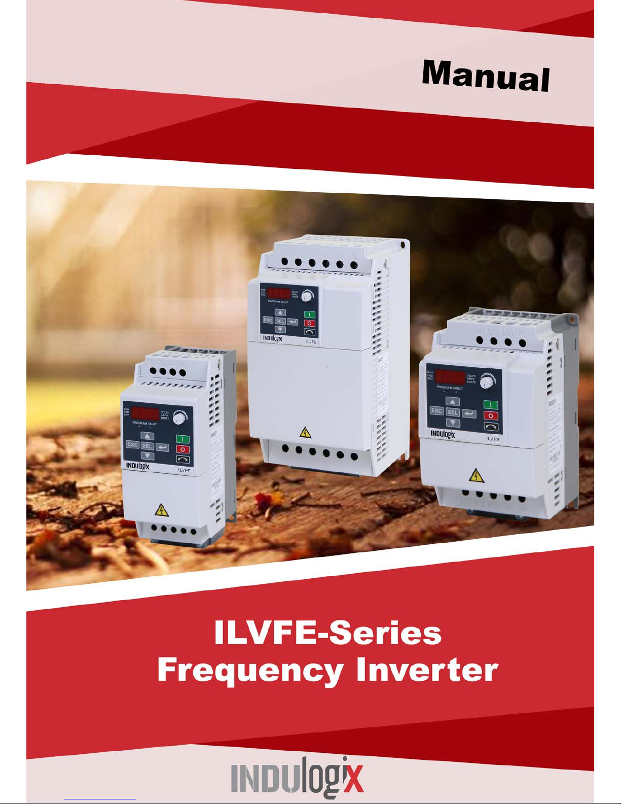
• Parameter numbers and names are shown in this format:
Drive frame sizes
Similar ILVFE drive sizes are grouped into fr ame sizes to sim plify spare parts or dering, dim ensioning,
etc.
A cross-reference of drive catalog numbers and their respective frame sizes is provided in Appendix B.
ILVFE-series user manual
7
General Precautions
ATTENTION: To avoid an electric shock hazard, ver ify that the v oltage on the bus
capacitors have discharged before performing any work on the drive.
Measure the DC bus voltage at the DC– and DC+ terminals on the Power
Terminal Block (refer to Chapter 1 Power Terminal descriptions).
The voltage must be zero.
Darkened LEDs or a darkened displa y are not an indication that capacitors
have discharged to safe voltage levels.
ATTENTION: Only qualified personnel familiar with adjustable frequency AC
drives and associated machinery should plan or implement the installation, start-up
and subsequent maintenance of the system.
Failure to comply may result in personal injury and/or equipment damage.
ATTENTION: This drive contains ESD (Electrostatic Discharge) sensitive parts
and assemblies. Static control precautions are required when installing, testing,
servicing or repairing this assembly.
Component damage may result if ESD control procedures are not followed.
ATTENTION: An incorrectly applied or installed drive can result in component
damage or a reduction in product life. W iring or applicat ion errors, such as, under
sizing the motor, incorrect or inadequate AC supply, or excessive ambient
temperatures may result in malfunction of the system.
ATTENTION: The bus regulator function is extremely useful for preventing
nuisance over voltage fau lts resulting from aggressive dec elerations, overhauling
loads, and eccentric loads.
However, it can also cause either of the following two conditions to occur:
1. Fast positive changes in input voltage or imbalanced input voltages can
cause uncommanded positive speed changes;
2. Actual deceleration times can be longer than commanded deceleration
times. However, a “Sta ll Fault” is gener ated if the drive remains in this stat e
for 1 minute. If this condition is unacceptable, the bus regulator must be
disabled. In addition, inst alling a properly sized dynam ic brake resistor will
provide equal or better performance in most cases.

8
ILVFE-series user manual
Model number explanation
Indulogix Series Code
Number of phases:
1. Single phase
3. Three phase
Power Rating
Drive Ratings
Model Frame Size W x H x D
Input
Voltage
kW HP
Output
Current(A)
200 ~240V
1-Phase
With filter
0.75 1 4.2
ILVFE-1W0075
A 72 x 185.5 x146
1.50 2 8.0
ILVFE-1W0150
B
100 x 174 x 146.5
2.20 3 11
ILVFE-1W0220
B
100 x 174 x 146.5
380 ~460V
3-Phase
With filter
0.75 1 2.5
ILVFE-3W0075
A
72 x 185.5 x146
1.50 2 4.2
ILVFE-3W0150
A
72 x 185.5 x146
2.20 3 6.0
ILVFE-3W0220
B 100 x 174 x 146.5
3.70 5 8.7
ILVFE-3W0370
B
100 x 174 x 146.5
5.50
7.5
13.0
ILVFE-3W0550
C
130 x 258 x 189.8
7.50
10
18.0
ILVFE-3W0750
C
130 x 258 x 189.8
11.00
15
24.0
ILVFE-3W1100
C
130 x 258 x 189.8
ILVFE-series user manual
9
Chapter 1 - Installation/Wiring
This chapter provides information on mounting and wiring the ILVFE Drive.
Most start-up difficulti es are the result of incorrect wiring. Every precaution mus t be taken to assure
that the wiring is done as instructed. All items must be read and understood before the actual
installation begins.
ATTENTION: The following information is merely a guide for proper installation.
Indulogix, cannot assum e responsibilit y for the compliance or the nonc ompliance to
any code, national, local or otherwise for the proper installation of this drive or
associated equipment.
A hazard of persona l injury and/or equipment damage ex ists if codes are ignored
during installation.
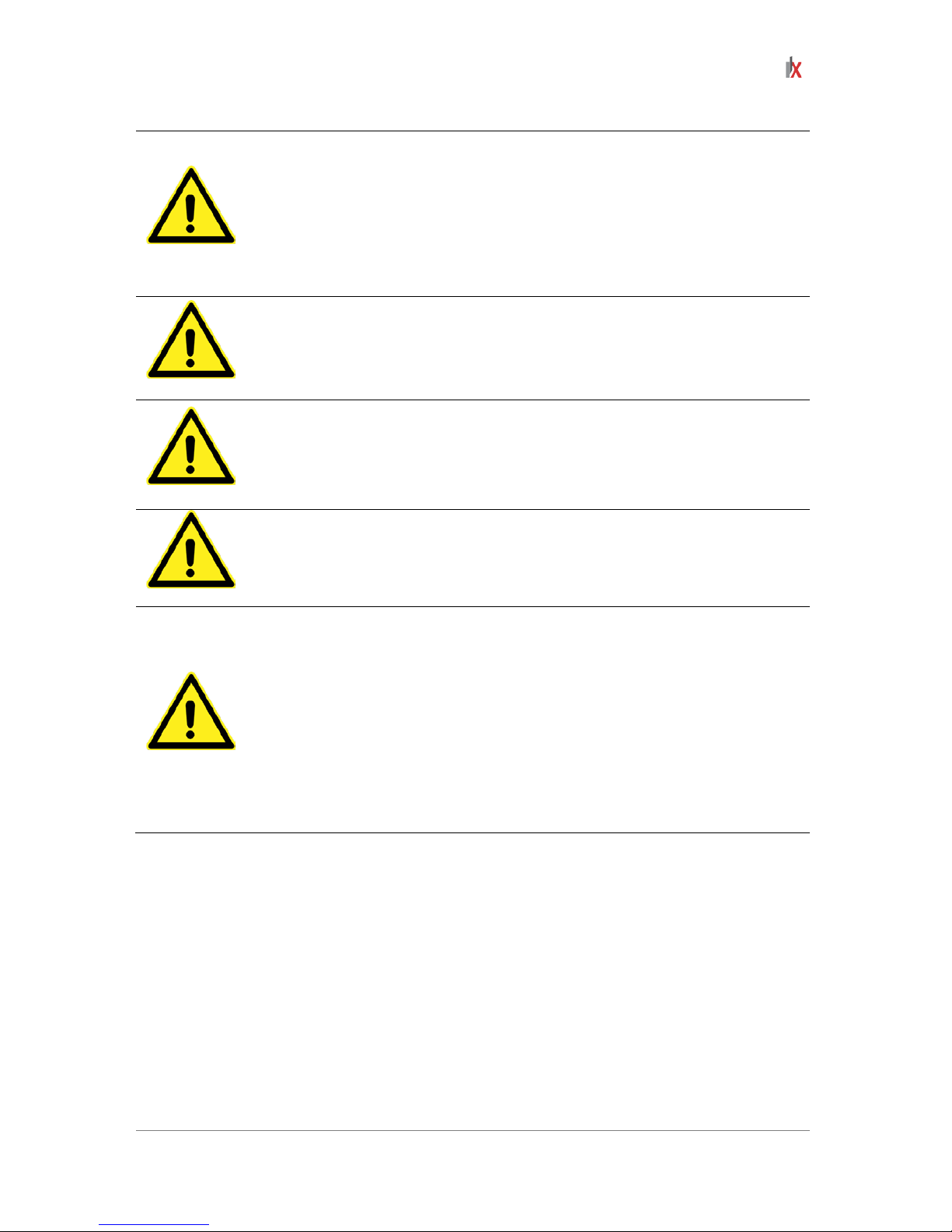
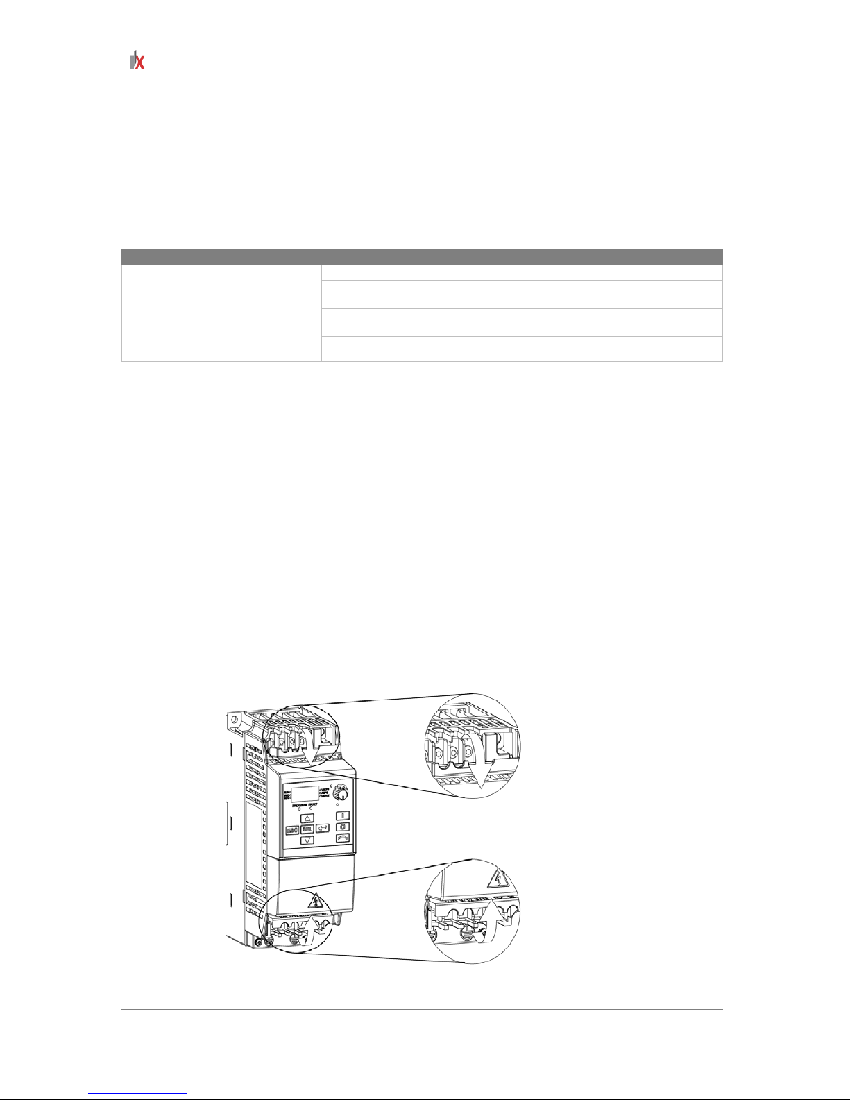
Opening the cover
Pull the cover out and up to release
10
ILVFE-series user manual
Mounting the unit
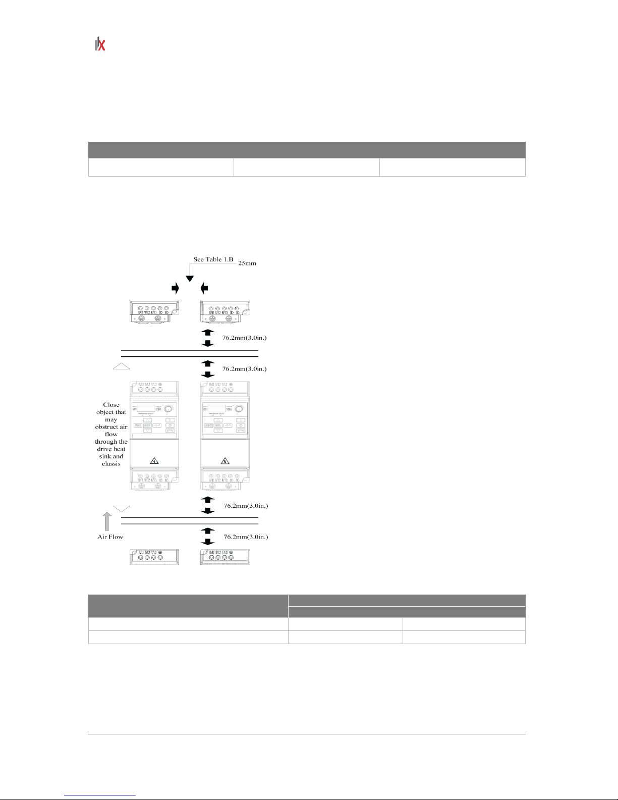
Mount the drive upright on a flat, vertical and level surface.
Install on 35mm DIN-Rail (for frames A and B) or install with screws (see table 1.A below).
Table 1.A Screw mounting recommendations
Minimum Panel Thickness Screw Size Mounting Torque
1.9 mm (0.0747 inch.) M4 (#8-32) 1.56 – 1.96 N-m (14-17 lb. –in)
• Protect the cooling fan by avoiding dust or metallic particles.
• Do not expose to a corrosive atmosphere.
• Protect from moisture and direct sunlight.
Minimum Mounting Clearances
Table 1.B
Horizontal clearance between drives
Ambient Temperature
Minimum
Maximum
0 mm and greater
-10°C (14°F)
40°C (104°F)
25 mm and greater
-10°C (14°F)
50°C (122°F)
Storage
• Store within an ambient temperature of -40°C to +85°C.
• Store within a relative humidity range of 0% to 95%, non condensing.
• Do not expose to corrosive atmosphere.
ILVFE-series user manual
11
AC supply source considerations
Ungrounded Distribution Syste ms
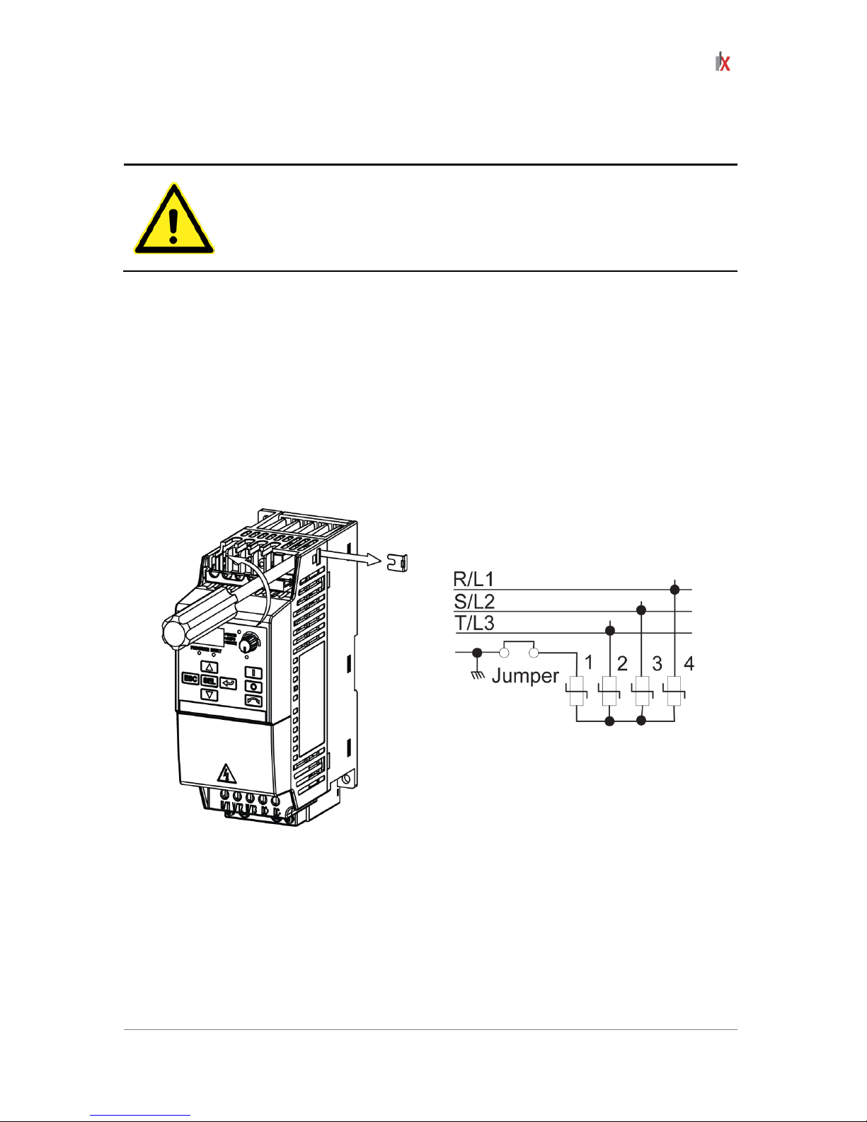
ATTENTION: ILVFE drives contain protective MOVs that are referenc ed to ground.
These devices must be dis connected if the drive is installed on an ungrou nded or
resistive grounded distribution system.
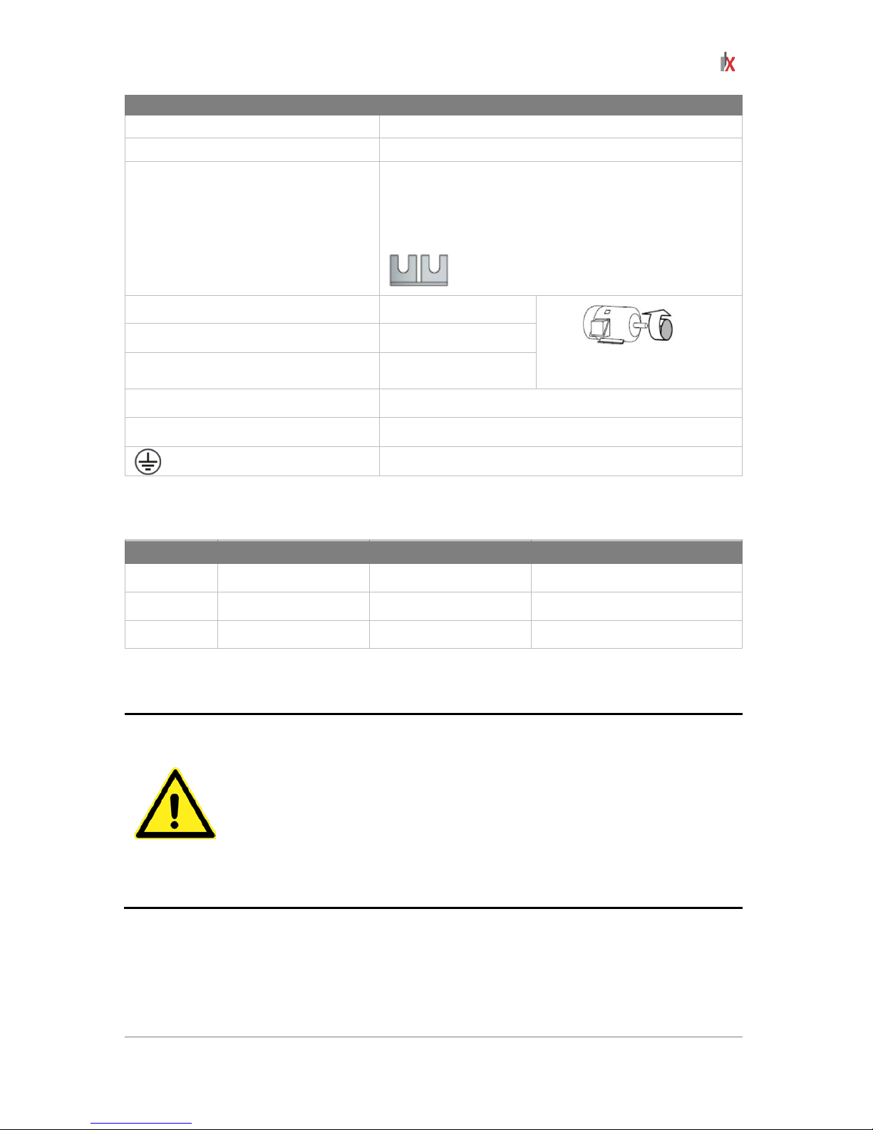
Disconnecting MOVs
To prevent drive damage, the MO Vs c onn ec ted t o gr o und s ha ll be dis connected if the drive is instal le d
on an ungrounded distr ibution system where th e line-to-ground voltages on any phase could excee d
125% of the nom inal line-to-line voltage. To disconn ect these devices, remove the jumper shown in
the Figures 1.1 and 1.2 below
1. Turn the screw counterclockwise to loosen.
2. Pull the jumper completely out of the drive chassis.
3. Tighten the screw to keep it in place.
Figure 1.1 Jumper Location (Frame A shown)
Figure 1.2 Phase to Ground MOV Removal
Important: Tighten screw after jumper removal.
3-Phase AC Input

12
ILVFE-series user manual
Input Power Conditioning
The drive is suitable for direct connection to input power within the rated voltage of the drive
(see Appendix A).
Listed in Table 1.C are certain input power conditions which may cause component damage
or reduction in product life.
If any of the conditions exist as described in Table 1.C, install one of the devices listed under
the heading Corrective Action on the line side of the drive.
Important: Only one device per branch circuit is required. It should be mounted closest to
the branch and sized to handle the total current of the branch circuit.
Table 1.C Input Power Conditions
Input power condition Corrective action
Low line impedance (less than 1% line reactance)
• Install line reactor.
• Install isolation transformer.
Greater than 120 kVA supply transformer
Line has power factor correction capacitors
Line has frequent power interruptions
Line has intermittent noise spikes in excess of 6000V (lightning)
Phase to ground voltage exceeds 125% of normal line voltage
• Remove MOV jumper to
ground.
• Install isolation transformer with
grounded secondary if
necessary.
Ungrounded distribution system
ILVFE-series user manual
13
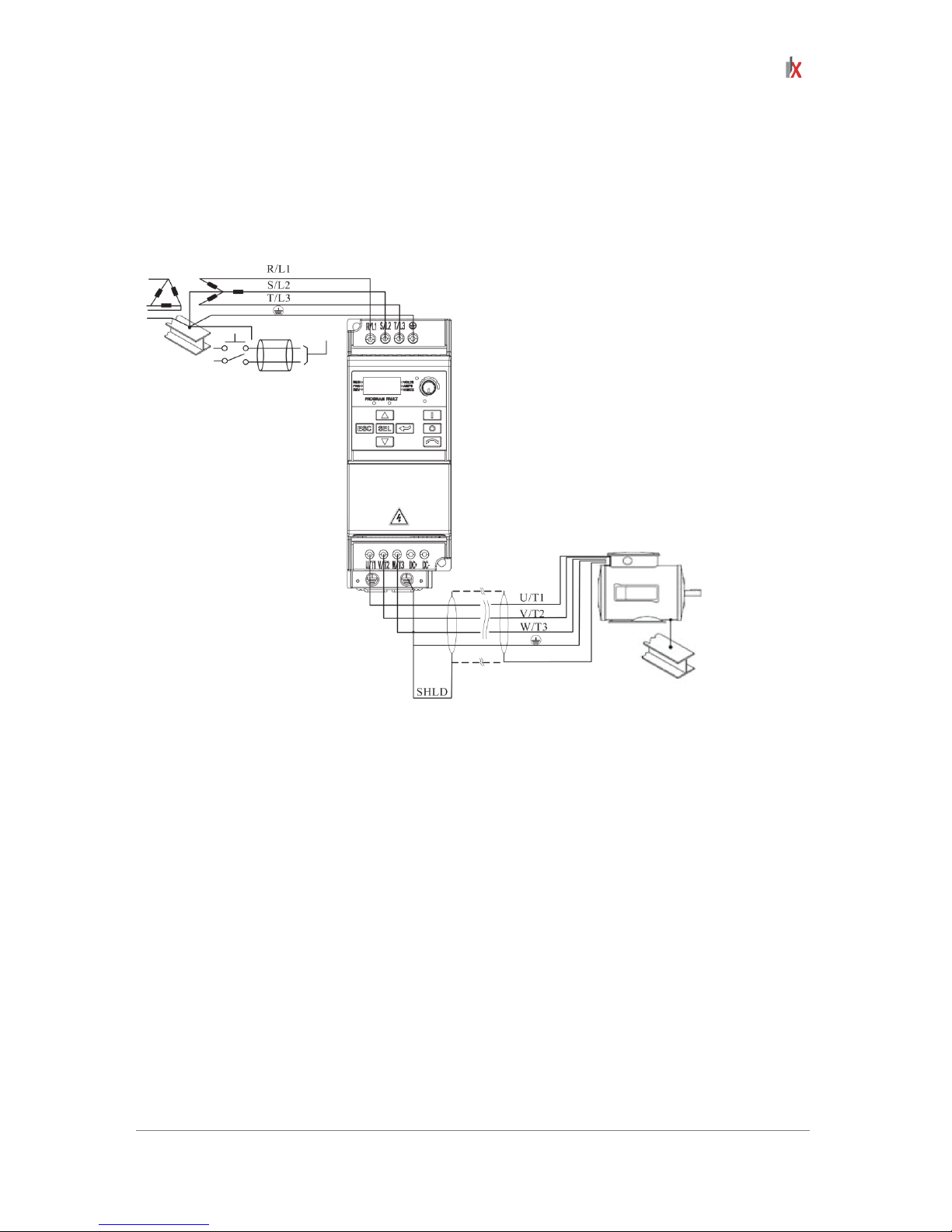
General grounding requirem e nt s
The drive safety ground (PE) must be connected to system ground.
Ground impedance mus t conf orm to the r equirements of national and local indus t rial s af et y regulat io ns
and/or electrical codes. The integrity of all ground connections should be periodically checked
.
Figure 1.3 Typical grounding
Safety Ground – (PE)
This is the safet y groun d f o r the dr ive that is re quired by code. One of thes e po ints must be connected
to adjacent building steel (girder , joist), a floor ground rod or bus bar. Grounding points must compl y
with national and local industrial safety regulations and/or electrical codes.
Shield Termination – SHLD
Either of the safety groun d terminals located on the po wer terminal block provides a grounding point
for the motor cable shield.
The motor cable shield co nnected to one of these t erminals (drive end) sho uld also be connected to
the motor frame (m otor end ) . Us e a shield terminating or EMI c lamp to connect the shie ld to t he s af ety
ground terminal.
The conduit box option may be used with a cable clamp for a grounding point for the cable shield.
When shielded cable is us e d f or c ontrol an d s ig nal w iri ng, th e s hi eld sh ou ld b e grounded at the source
end only, not at the drive end.
14
ILVFE-series user manual
RFI Filter Grounding
Using single phase drives with integral filter, or an external filter with any drive rating, may result in
relatively high ground leakage currents. Therefore, the filter must onl y be used in installations with
grounded AC supply systems and be permanently installed and solidly grounded (bonded) to the
building power distribution gr oun d.
Ensure that the incoming supply neutral is solidly connected (bonded) to the same building power
distribution ground. Gr o und ing must not rely on flexibl e c abl es and should not incl ude any form of plug
or socket that would permit inadvertent disconnection. Some local codes may require redundant
ground connections. The integrity of all connections should be periodically checked.
Fuses and circuit breakers
The ILVFE drive does not prov ide branch short c ircuit pr otect ion. T his prod uct s houl d be ins talle d with
either input fuses or an input circuit breaker. National and local industrial safety regulations and/or
electrical codes may determine additional requirements for these installations.
ATTENTION: To guard against personal injury and/or equipment damage caused
by improper fusing or circuit breaker selection, use only the recommended line
fuses/circuit breakers specified in this section.
Fusing
The ratings in the table that follows are the maximum recommended values for use with each drive
rating. The devices listed in this table are provided to serve as a guide.
Rated Voltage Drive Rating KW (HP Fuse Rating A
200 ~ 240V AC 1-Phase
0.75 (1.0) 15
1.5 (2.0) 35
2.2 (3.0) 40
380 ~ 460V AC 3-Phase
0.75 (1.0) 6
1.5 (2.0) 10
2.2 (3.0) 10
3.7 (5.0) 15
5.5 (7.5) 25
7.5 (10.0) 30
11.0 (15.0) 50

ILVFE-series user manual
15
Power wiring
ATTENTION: National codes and standards and local codes outline provisions for
safely installing electrical equipment. Installation must comply with specifications
regarding wire types, conductor sizes, branch circuit protection and disconnect
devices. Failure to do so may result in personal injury and/or equipment damage.
ATTENTION: To avoid a possible shock hazard caused by induced voltages,
unused wires in the conduit must be grounded at both ends. For the same reason, if
a drive sharing a conduit is being serviced or installed, all drives using this conduit
should be disabled. This will help minimize the possible shock hazard from
“cross coupled” power leads.
Motor Cable Types Acceptable for 200-600 Volt Installations
General
A variety of cable types are acceptab le for drive ins tallations . For m any installatio ns, unshield ed cable
is adequate, provided it ca n be separated from sensitive circuits. As an approx imate guide, allow a
spacing of 0.3 meters (1 foot) f or every 10 meters (32.8 f eet) of length. In all cas es, long parallel runs
must be avoided.
Do not use cable with an insulation th ickness less than 15 m ils (0.4 mm/0.015 in.) . Do not route more
than three sets of motor leads in a single conduit to minimize “cross talk”. If more than three
drive/motor connections per conduit are required, shielded cable must be used.
Shielded
Location Rating/Type Description
Standard (option 1) 600V, 75°C or 90°C (167°F or 194°F)
RHH/RHW-2
• 4 tinned copper conductors with
XLPE insulation.
• Foil shield and tinned copper drain
wire with 85% braid coverage.
• PVC Jacket
Standard (option 2) 600V, 75°C or 90°C (167°F or 194°F)
RHH/RHW-2
• 3 tinned copper conductors with
XLPE insulation
• 5 mil single helical copper tape
(25% overlap min.) with 3 bare
copper grounds in contact with
shield.
• PVC Jacket
16
ILVFE-series user manual
Reflected wave protection
The drive should be ins talled as close to the motor a s possible. Installations with lo ng motor cables
may require the addi tion of external devices to lim it voltage reflections at the motor (r eflected wave
phenomena). See Table 1.E for recommendations.
The reflected wave data applies to all frequencies 2 to 10 kHz. For 240V ratings, reflected wave
effects do not need to be considered.
Table 1.E Maximum cable length recommendations
Reflected wave
380 ~460V Ratings
Motor insulation rating
Motor cable only*
1000 Vp-p 15 meters (49 feet)
1200 Vp-p 40 meters (131 feet)
1600 Vp-p 170 meters (558 feet)
* Longer cable lengths can be achieved by installing devices on the output of the drive. Consult factory for recommendations.
Output disconnect
The drive is intended to be commanded by control input signals that will start and stop the motor.
A device that routinely disconnects then reapplies output power to the motor for the purpose of starting
and stopping the motor should not be used.
If it is necessary to discon nec t pow er to th e m otor wit h the dri ve output ting p o wer, an aux iliar y contac t
should be used to simultaneously disable drive control run commands.
Power terminal Block
The drive utilizes a finger guard over the power wiring terminals.
To remove:
1. Press in and hold the locking tab.
2. For the finger guard on the top of the drive, slide it down and out.
For the finger guard at the bottom of the drive, slide it up a nd out. Replace the finger guard when
wiring is complete.
ILVFE-series user manual
17
Terminal
Description
R/L1, S/L2 1-Phase input
R/L1, S/L2, T/L3 3-Phase input
P1 (1), P2 (1)
DC Bus Inductor Connection (Frame C drives only.)
The Frame C drive is shipped with a jumper between
Terminals P1 and P2. Remove this jumper only when a
DC Bus Inductor will be c o nnec te d. Dr i ve wi ll not p o w er up
without a jumper or inductor connected.
U/T1 To motor U/T1
Switch any 2 motor leads to
change forward direction.
V/T2 To motor V/T2
W/T3 To motor W/T3
DC+, DC- DC bus connection
BR+, BR-* Dynamic brake resistor connection
Safety ground - PE
* For frame C only [5.5 kW (7.5 HP), 75.5 kW (10.07.5 HP),11.0 5.5 kW (15.0 HP)].
Table 1.F Power terminal block specifications
Frame Maximum wire size * Minimum wire size Torque
A 3.3 mm2 (12 AWG) 0.8 mm2 (12 AWG) 1.4-1.6 N-m (12-14 lb.-in)
B 8.4 mm2 (8 AWG) 0.8 mm2 (12 AWG) 1.6-1.9 N-m (14-17 lb.-in)
C 13.3 mm2 (6 AWG) 3.3 mm2 (12 AWG) 2.7-3.2 N-m (24-28 lb.-in)
* Maximum/minimum sizes that the terminal block will accept - these are not recommendations.
Motor start/stop precautions
ATTENTION: A cont actor or other device that ro utinely disconnects and reapplies
the AC line to the drive to start and stop the motor can cause drive hardware
damage. The drive is desi gned to use control input signals that will st art and stop
the motor. If used, the in put device must not exceed one operat ion per minute or
drive damage can occur.
ATTENTION: The drive start/s top control circuitry inc ludes solid-state com ponents.
If hazards due to acc idental contact with moving machiner y or unintentional flow of
liquid, gas or solids exist, an additional hardwired stop circuit may be required to
remove the AC line to t h e d rive. When the AC line is re moved, there will be a los s of
any inherent regenerati ve braking ef fect that m ight be present - the motor will coast
to a stop. An auxiliary braking method may be required.
18
ILVFE-series user manual
I/O wiring recommendations
Important points to remember about I/O wiring:
• Always use copper wire.
• Wire with an insulation rating of 600V or greater is recommended.
• Control and signal wires should be separated from power wires by at least 0.3 meters (1 foot).
Important: I/O terminals labeled “Common” are not referenced to the safety ground (PE) terminal and
are designed to greatly reduce common mode interference.
ATTENTION: Driv ing the 4-20mA analog input from a voltage source c ould cause
component damage.
Verify proper configuration prior to applying input signals.
Control wire types
Table 1.G Recommended control and signal wire*
Wire type(s) Description Minimum insulation rating
Shielded wire
0.8 mm
2
(18 AWG), twisted pair, 100%
shield with drain.
300V
60°C (140°F)
0.8 mm2 (18 AWG), 3 conductor, shielded
for remote pot only.
* If the wires are short and contained within a cabinet which has no sensitive circuits, the use of shielded wire may not be
necessary, but is always recommended.
I/O terminal block
Table 1.H Terminal Block specifications*
Maximum wire size* Minimum wire size* Torque
1.3 mm2 (16 AWG) 0.2 mm2 (24 AWG) 0.5-0.8 N-m (4.4-7 lb.-in.)
* Maximum/minimum sizes that the terminal block will accept - these are not recommendations.
Maximum control wire recommendations
Do not exceed control wiring length of 30 meters (100 feet). Control signal cable length is highly
dependent on electrical environment and installation practices.
To improve noise immunity, the I/O terminal block Common must be connected to ground
terminal/protective earth.
If using the RS485 (DSI) p ort, I/O T erminal 16 sh ould also be c onnec ted to grou nd terminal/ protectiv e
earth.
ILVFE-series user manual
19
Figure 1.5 Control wiring Block diagram
No Signal Default Description Parameter
R1
Relay N.O. Fault Normally open contact for output relay.
t221
R2
Relay Common - Common for output relay.
R3
Relay N.C. Fault Normally closed contact for output relay.
t221
Sink/Source DIP switch
Source
(SRC)
Inputs can be wired as Sink (SNK) or Source (SRC) via DIP
Switch setting.
01 Stop
(1)
Coast
The factory installed jumper or a normally
closed input must be present for the drive to
start.
P106
02 Start/Run FWD
(2)
Not active
Command comes from the integral keypad by
default. To disable reverse operation, see A095
[Reverse Disable].
P106, P107
03
Direction/Run REV Not active
P106, P107,
A434
04
Digital common
-
For digital inputs. Electronically isolated with
digital inputs from analog I/O.
05
Digital input 1 Preset freq Program with t201 [Digital In1 Sel].
t201
06
Digital input 2 Preset freq Program with t202 [Digital In2 Sel].
t202
11
+24V DC
-
Drive supplied power for digital inputs.
Maximum output current is 100mA
12
+10V DC +10V DC
Drive supplied power for 0-10V external
potentiometer.
Maximum output current is 15mA.
P108
13 0-10V in*
Not active
For external 0-10V input supply (input
impedance = 100kΩ) or potentiometer wiper.
P108
14
Analog common -
For 0-10V In or 4-20mA In. Electronically
isolated with analog inputs from digital I/O.
15 4-20mA in*
Not active
For external 4-20mA input supply (input
impedance = 250Ω).
P108
16
RS485 shield -
Terminal should be connected to Safety ground
- PE when using the RS485 communications
port.
* Only one analog frequency source may be connected at a time. If more than one reference is connected at the same time, an
undetermined frequency reference will result.

20
ILVFE-series user manual
Important
(1)
: I/O Terminal 01 is always a coast to stop input except when P106 [Start Source] is set
to “3-Wire” control. In three wire control, I/O Terminal 01 is controlled by P107 [Stop Mode].
All other stop sources are controlled by P107 [Stop Mode].
The drive is shipped with a jumper installed between I/O Terminals 01 and 11. Remove this jumper
when using I/O Terminal 01 as a stop or enable input.
(2)
Two wire control shown. For 3-wire control use a momentary input on I/O Terminal 02 to
command a start. Use a maintained input for I/O terminal 03 to change direction.
Relay output ratings
30V DC 125V DC 240V DC
Resistive load 3.0A 3.0A 3.0A
Inductive load 0.5A 0.5A 0.5A
P106 [start source]
Stop
I/O terminal 01 [stop]
Keypad Parameter P107 Coast
3-Wire Parameter P107 Parameter P107
2-Wire Parameter P107 Coast
RS-485 Parameter P107 Coast
ILVFE-series user manual
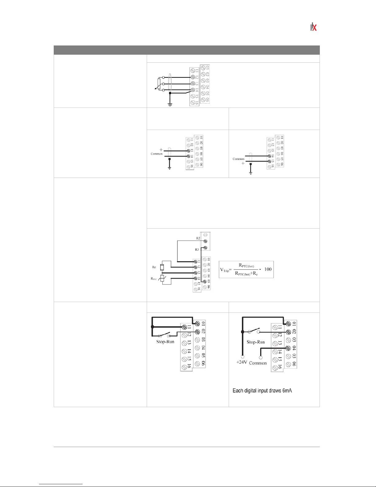
21
Input
Connection example
Potentiometer
1 ~ 10kΩ Pot. recommended
(2 Watt minimum)
P108 [Speed ref.]= 2 (0-10V Input)
Analog input
0 ~ 10V, 100kΩ impedance
4 ~ 20mA, 100Ω impedance
Voltage
P108 [Speed ref.]= 2
(0-10V Input)
Current
P108 [Speed ref.]= 3
(4-20mA Input)
Analog input: PTC
For detecting drive fault
Wire the PTC and External Resistor (typically matched to the
PTC Hot Resistance) to I/O Terminals 12, 13, 14.
Wire R2/R3 Relay Output (SRC) to I/O Terminals 5 & 11.
t201 [Digital In Sel.]= 3 (Aux fault)
t221 [Relay Out Sel.]= 10 (above anlg V)
t222 [Relay Out Level.]= % voltage trip
2-wire SRC control:
non-reversing
P106 [Start Source] = 2, 3 or 4
Input must be active for the driv e
to run.
When input is opened, the drive
will stop as specified by P107
[Stop Mode].
If desired, a User Supplied 24V
DC power source can be used.
Refer to
the “External Supply
(SRC)” example.
Internal supply (SRC) External supply (SRC)
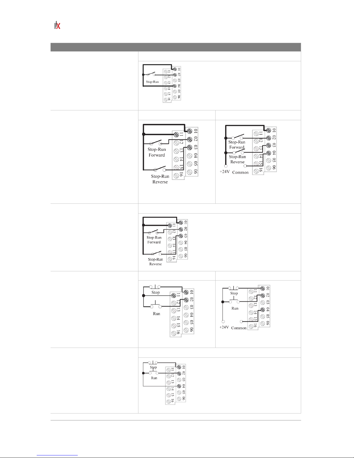
22
ILVFE-series user manual
Input
Connection example
2-wire SNK control:
non-reversing
Internal supply (SNK)
2-wire SRC control –
run FWD/ run REV
P106 [Start Source] = 2, 3 or 4
Input must be active for the driv e
to run.
When input is opened, the drive
will stop as specified by P107
[Stop Mode].
If both run forward and run
reverse inputs are closed at the
same time, an undetermined
state could occur.
Internal supply (SRC) External supply (SRC)
Each digital input draws 6mA
2-wire SNK control:
run FWD/ run REV
Internal supply (SNK)
3-wire SRC control:
non-reversing
P106 [Start Source] = 1
A momentary input will start the
drive.
A stop input to I/O Terminal 01
will stop the drive as spec ified by
P107 [Stop Mode].
Internal supply (SRC) External supply (SRC)
Each digital input draws 6mA
3-wire SNK control:
non-reversing
Internal supply (SNK)

ILVFE-series user manual
23
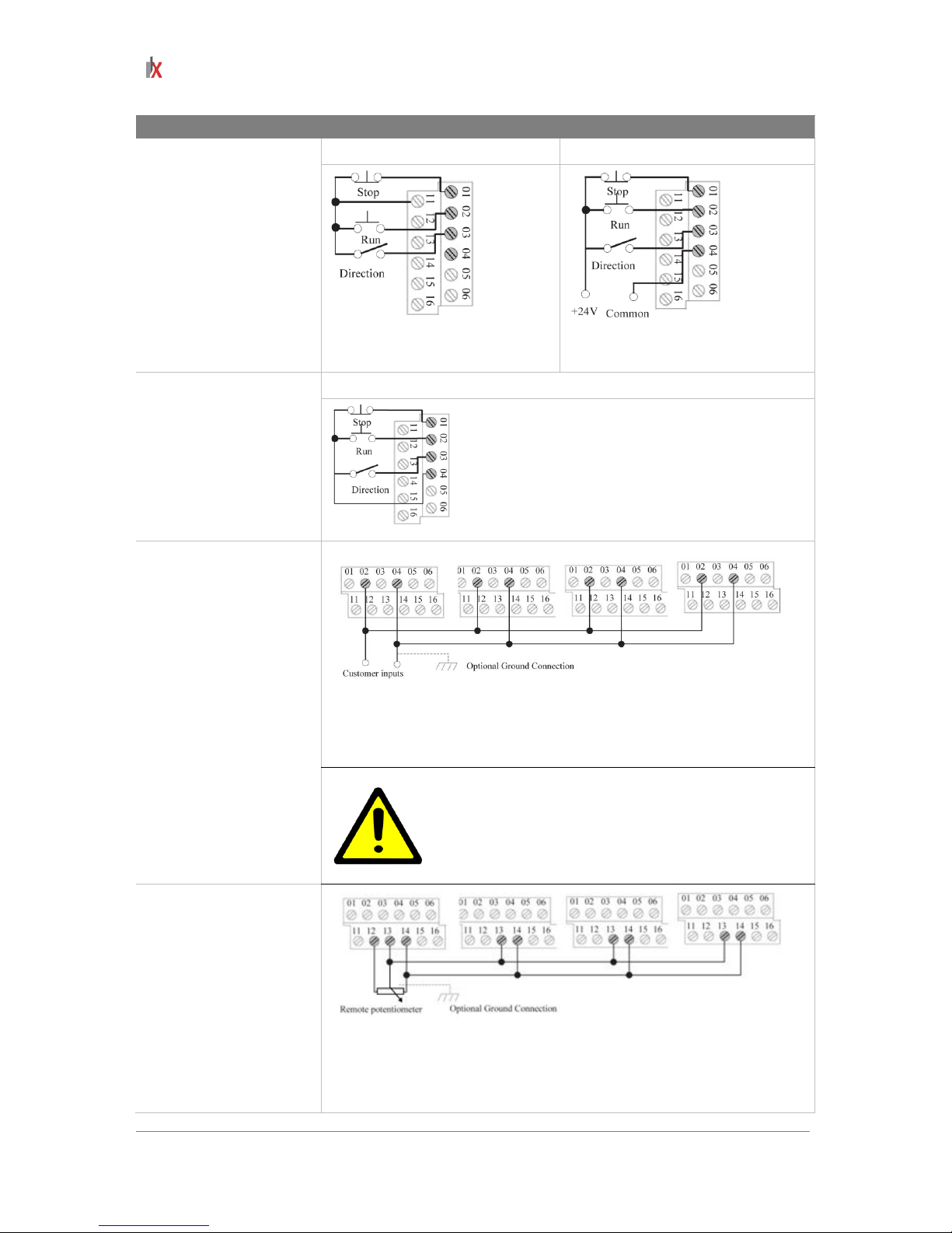
24
ILVFE-series user manual
Input
Connection example
3-wire SRC control:
reversing
P106 [Start Source] = 1
A momentary input will
start the drive.
A stop input to I/O
Terminal 01 will stop the
drive as specified by
P107 [Stop Mode].
I/O Terminal 03
determines direction.
Internal supply (SRC) External supply (SRC)
Each digital input draws 6mA
3-wire SNK control:
reversing
Internal supply (SNK)
Multiple digital input
connections
Customer inputs can be
wired per External supply
(SRC)
When connecting a single input such as Run, Stop, Reverse or Preset
Speeds to multiple drives, it is important to connect
I/O Terminal 04
common together for al l dr ives . If th e y ar e to be t ie d in to a noth er common
(such as earth ground or separate apparatus ground) only one point of
the daisy chain of I/O Terminal 04 should be connected.
ATTENTION: Digital inputs on multiple drives should
NOT be tied tog ether when using S NK (Internal Supp ly)
mode.
In SNK mode, if power is removed from one drive,
inadvertent operation of other drives that share the
same I/O Common connection may occur.
Multiple analog
connections
When connecting a sin gle potentiometer to m ultiple drives it is impor tant
to connect I/O Terminal 14 c ommon together for all drives. I/O Terminal
14 common and I/O Term inal 13 (potentiometer wiper ) should be daisychained to each drive.
All drives must be powered up for the analog signal to be read correctly.
ILVFE-series user manual
25
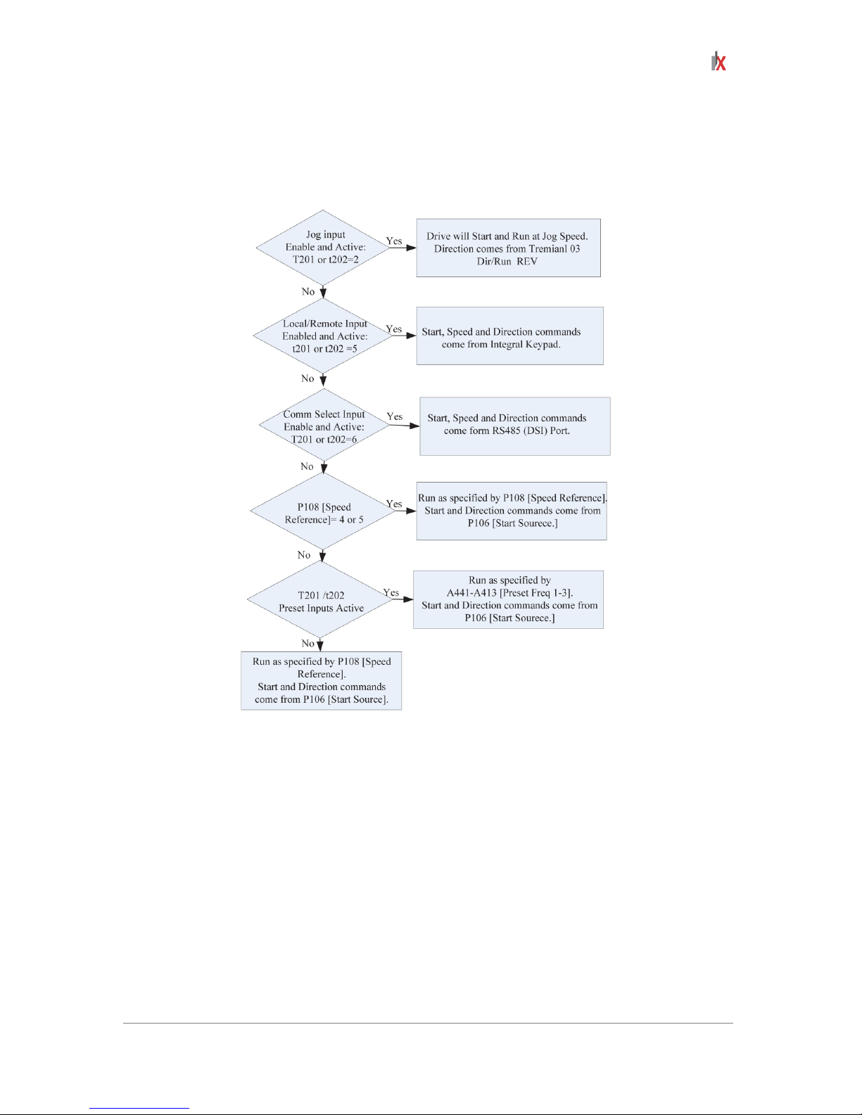
Start and speed reference control
The drive speed command can be obtained from a number of different sources. The source is
normally determined by P108 [Speed Refer ence]. H o wever, when t201 or t202 Digita l In x S el is se t t o
option 2, 4, 5 or 6, and the digital input is active, t201 or t202 will override the speed reference
commanded by P108 [Speed Reference]. See the chart below for the override priority.
Acceleration/deceleration selection
 Loading...