


C olour Televis ion
C olour Televis ion
OwnerÕs Manual
P /NO : MAN05GDP045
L D-42IU21
P lease read this manual carefully before operating your set.
R etain it for future reference.
S ee the label attached on the back cover and quote this information to your dealer when you require service.
WARNING:
TO PREVENT FIRE OR SHOCK HAZARDS, DO NOT EXPOSE
THIS PRODUCT TO RAIN OR MOISTURE.
NOTE TO CABLE/TV INSTALLER:
This reminder is provided to call the CATV system installer’s
attention to Article 820-40 of the National Electric Code
(U.S.A.). The code provides guidelines for proper grounding
and, in particular, specifies that the cable ground shall be connected to the grounding system of the building, as close to the
point of the cable entry as practical.
REGULATORY INFORMATION
This equipment has been tested and found to comply with the
limits for a Class B digital device, pursuant to Part 15 of the
FCC Rules. These limits are designed to provide protection
against harmful interference in a residential installation. This
equipment generates, uses and can radiate radio frequency
energy and, if not installed and used in accordance with the
instructions, may cause harmful interference to radio communications. However, there is no guarantee that interference will
not occur in a particular installation. If this equipment does
cause harmful interference to radio or television reception,
which can be determined by turning the equipment off and on,
the user is encouraged to try to correct the interference by one
or more of the following measures:
- Reorient or relocate the receiving antenna.
- Increase the separation between the equipment and receiver.
- Connect the equipment into an outlet on a circuit different from
that to which the receiver is connected.
- Consult the dealer or an experienced radio/TV technician for
help.
Any changes or modifications not expressly approved by the
party responsible for compliance could void the user’s authority to operate the equipment.
Warning
2
WARNING:
TO REDUCE THE RISK OF ELECTRIC SHOCK DO NOT REMOVE COVER (OR BACK). NO USER SERVICEABLE PARTS INSIDE. REFER TO QUALIFIED SERVICE PERSONNEL.
The lightning flash with arrowhead symbol, within an equilateral triangle, is intended to alert the user to
the presence of uninsulated “dangerous voltage” within the product’s enclosure that may be of sufficient
magnitude to constitute a risk of electric shock to persons.
The exclamation point within an equilateral triangle is intended to alert the user to the presence of important operating and maintenance (servicing) instructions in the literature accompanying the appliance.
CAUTION
RISK OF ELECTRIC SHOCK
DO NOT OPEN

Important S afety Ins tructionS
“WARNING – To reduce the risk of fire or electric shock, do not expose the
apparatus to rain or moisture.”
“The apparatus shall not be exposed to dripping or splashing and no objects filled with liquids,
such as vases, shall be placed on the apparatus."
1) R ead these instructions.
2) K eep thes e instructions.
3) Heed all warnings.
4) F ollow all ins tructions .
5) Do not use this apparatus near water.
6) C lean only with dry cloth.
7) Do not block a ny ventilation openings . Install in a ccordance with the manufacturer's
instructions.
8) Do not install nea r any heat s ources s uch as radiators, hea t regis ters, stoves ,
or other apparatus (including amplifiers) that produce heat.
9) Do not defeat the safety purpos e of the polarized or grounding-type plug.
A polarized plug has two blades with one wider than the other.
A grounding type plug has two blades and a third grounding prong.
T he wide blade or the third prong are provided for your s afety.
If the provided plug does not fit into your outlet, consult an electrician for replacement
of the obsolete outlet.
10) P rotect the power cord from being walked on or pinched particularly at plugs,
convenience receptacles, and the point where they exit from the apparatus.
11) O nly use a ttachments/acces s ories specified by the manufacturer.
12) U s e only with the cart, stand, tripod, bracket, or table s pecified by the manufacturer,
or sold with the apparatus. When a cart is us ed, use ca ution when moving the ca rt/apparatus
combination to a void injury from tip-over.
.
13) U nplug this apparatus during lightning storms or when unus ed for long periods of time.
14) R efer all servicing to qualified s ervice pers onnel. S ervicing is required when the apparatus
has been damaged in any way, such as power-supply cord or plug is damaged,
liquid has been s pilled or objects have fallen into the appara tus, the appara tus has been expos ed
to rain or moisture, does not operate normally, or has been dropped.
- T he apparatus s ha ll not be exposed to dripping or splashing and that no objects filled with liquids,
s uch as vases, shall be placed on the apparatus.
- Minimum distances(e.g. 10cm) around the appara tus for sufficient ventilation

Warnings 2
Safety Instructions 3-5
Contents 6
Location and function of controls 7-10
Remote control handset
Battery installation
Front panel
Back panel
Connection to External equipment 11-15
Basic operation 16
On and Off / Programme selection
Volume adjustment
On screen language selection (option)
On screen menus 17
Menu selection
Setting up TV stations 18-20
Memorizing the Channels with Auto
Add/Delete Channels with Manual
Fine Tuning Adjustment / BOOSTER
Favorite Channels Setup
Picture Menu 21-23
CSM (Colour Status Memory)
PSM (Picture Status Memory)
Manual Picture Control
Picture Format
Sound Menu 24-27
SSM (Sound Status Memory)
Balance
AVL (Auto Volume Leveler)
SPDIF Format
Stereo/SAP Broadcasts Setup
Audio Language
Time Menu 28-31
Clock
On/Off Time
Auto sleep
Time Zone
Sleep timer
Setup Menu 32
Child lock
Caption Menu 33-34
Caption On/Off
Analog CAP/TXT
DTV CAP Setup
DTV CAP Color
Lock Menu (option) 35-37
Lock Menu options
Lock Menu Setup
EPG ( Electronic Programme Guide)
/ Information 38
RGB-PC Menu 39
PC Setup
PIP (Picture-In-Picture) Feature 40-41
Displayable Monitor Specification 42
Troubleshooting Check list 43
Contents
6
7
EN
Location and function of controls
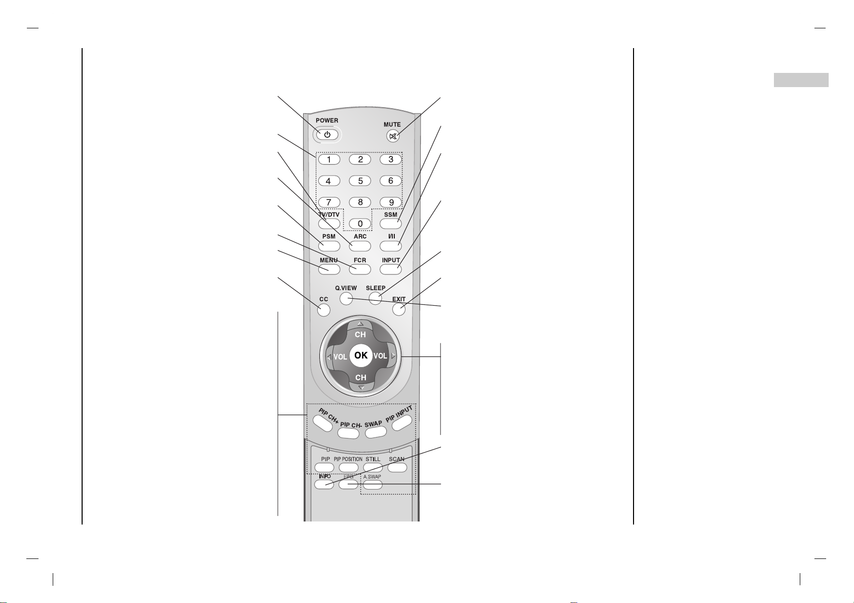
Remote control handset
- All the functions can be controlled with the remote control handset.
- Some functions can also be adjusted with the buttons on the front panel of the set.
- Before you use the remote control handset, please install the batteries.
POWER
Switches the set On from standby or Off
to standby.
NUMBER BUTTONS
TV/DTV
Select TV, DTV mode.
ARC
Select your desired picture format.
PSM (Picture Status Memory)
Recalls your preferred picture setting.
FCR (Favorite Channels Setup)
MENU
Selects a menu.
CC
Select a closed caption : Off, EZ Mute,
and On.
PIP
Switches the sub picture on or off.
A.SWAP
PIP mode - main and sub picture audio
select.
PIP CH +/-
Selects a channel for the sub picture.
SWAP
Alternates between main and sub picture.
PIP INPUT
Selects the input mode for the sub pic-
ture.
PIP POSITION
Relocates the sub picture in clockwise
direction.
STILL
Freezes motion of the sub picture.
SCAN
Switches on the programme scan mode
through 4/16 sub pictures.
MUTE
Switches the sound on or off.
SSM (Sound Status Memory)
Recalls your preferred sound setting.
I/II
Selects the audio language during dual
language broadcast. (In Digital mode only)
Selects the sound output.
INPUT SELECT
Select TV, AV1, AV2, S-VIDEO, COMPONENT, PC-RGB, DVI mode.
Switches the set on from standby.
SLEEP
Sets the sleep timer.
EXIT
Exits from each mode.
Q.VIEW
Returns to the previously viewed programme.
D/ E
(Channel Up/Down)
Selects a channel or a menu item.
Switches the set on from standby.
F / G (Volume Down/Up)
Adjusts the volume.
Adjusts menu settings.
OK
Accepts your selection or displays the
current mode.
INFO
Displays information on top of the screen
during watching TV.
(In Digital mode only)
EPG
Shows a programme schedule.
(In Digital mode only)
OK
TV/DTV
PSM
MENU
CC
PIP CH+
PIP CH-
SWAP
PIP INPUT
CH
VOL
VOL
CH
Q.VIEW
A.SWAP
EPG
EXIT
SLEEP
INPUTFCR
ARC
POWER
MUTE
SSM
8
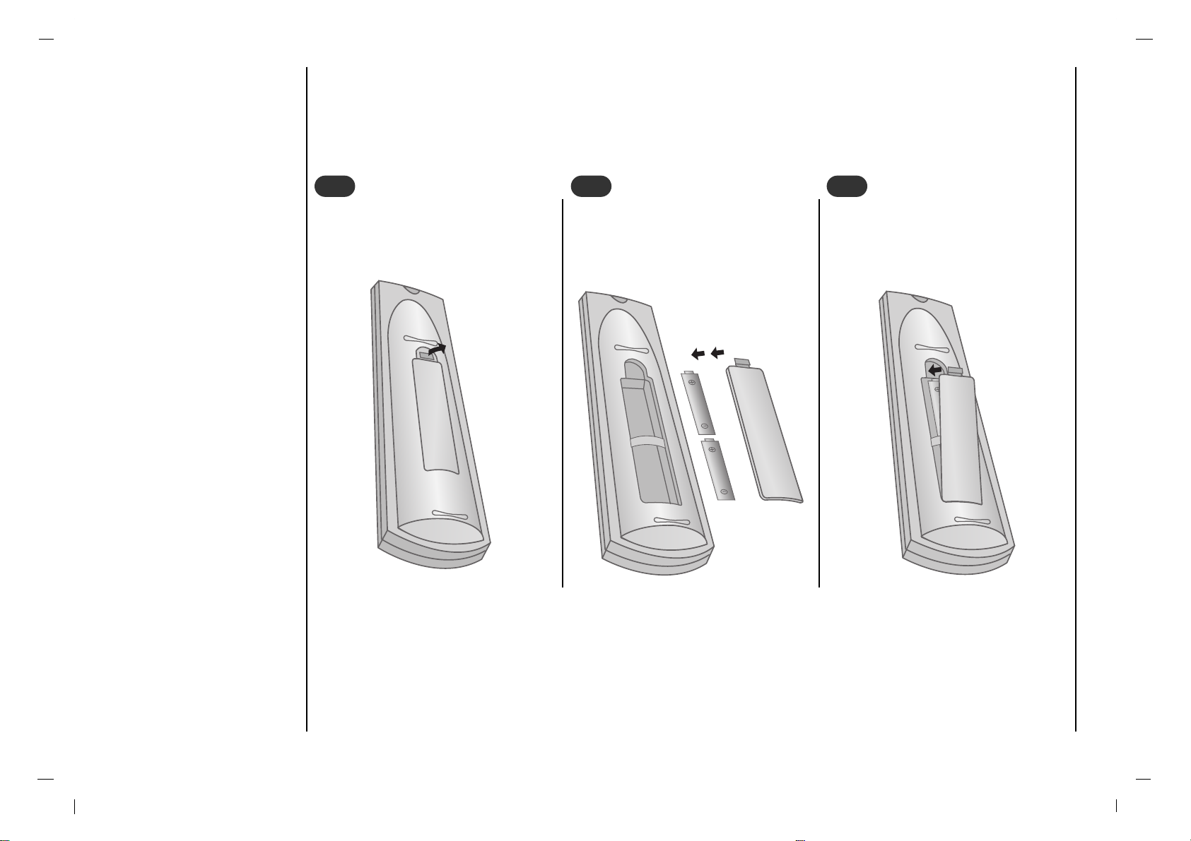
- Your remote control handset is powered by two AAA type batteries.
To insert batteries, turn the remote
control handset over and remove the
battery cover.
1
1
Put the two batteries into the compartment observing battery polarity.
2
2
Replace the cover.
To avoid damage from possible battery leakage, remove the batteries if you do not plan to
use the remote control handset for an extended
period time. Do not use batteries of differing
age or type. Always discard of batteries safely.
3
3
Location and function of controls
Battery installation
8
9
EN
Location and function of controls
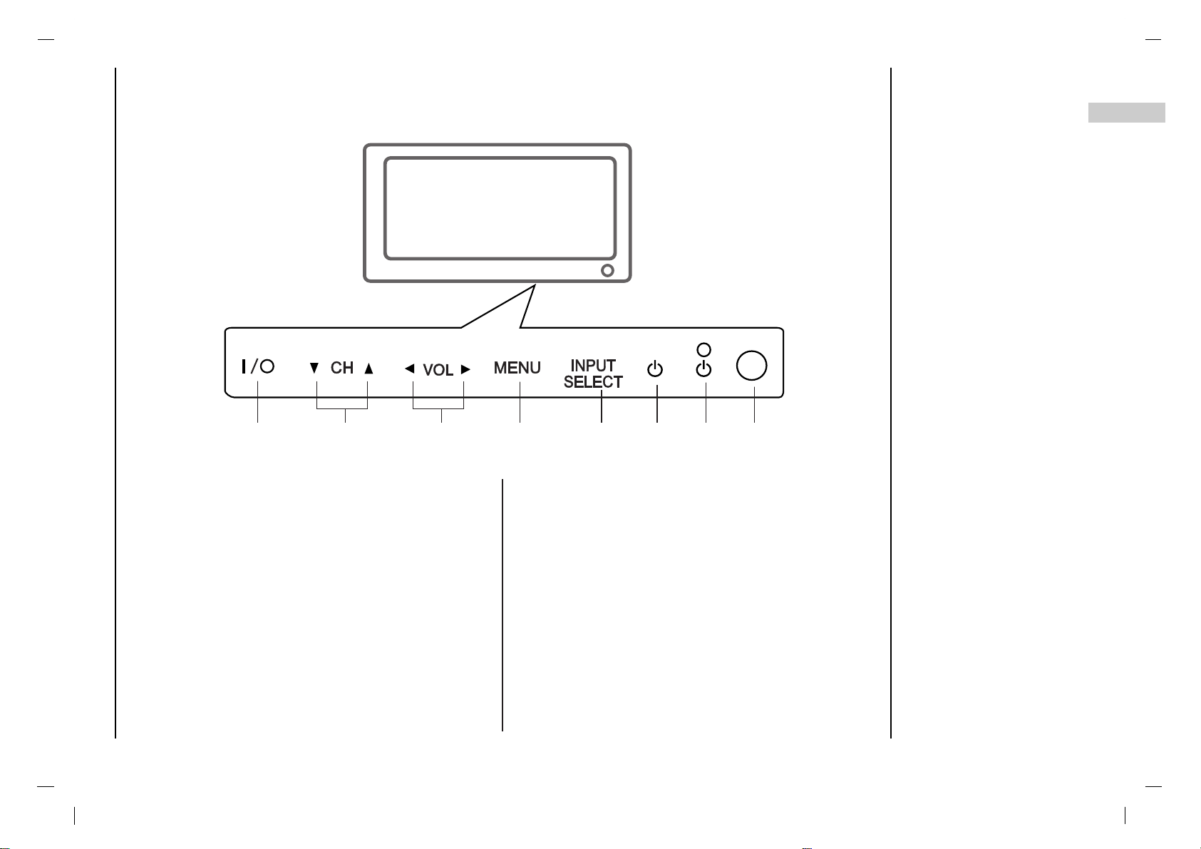
Front panel
1. MAIN POWER (I / yy)
Switches the set On or Off.
2.
D / E
(Channel Up/Down)
Selects a channel or a menu item.
Switches the set On from standby.
3. F / G (Volume Down/Up)
Adjusts the volume.
Adjusts menu settings.
4. MENU
Selects a menu.
5. INPUT SELECT
Select TV, AV1, AV2, S-VIDEO, COMPONENT, PCRGB, DVI mode.
6. POWER (rr)
Switches the set On from standby or On to standby.
7. POWER/STANDBY INDICATOR (rr)
Illuminates red in standby mode.
Illuminates green when the set is switched on.
8. REMOTE CONTROL SENSOR
- Shown is a simplified representation of the set.
- Here shown may be somewhat different from your set.
1
4 5 6 7 8
2 3
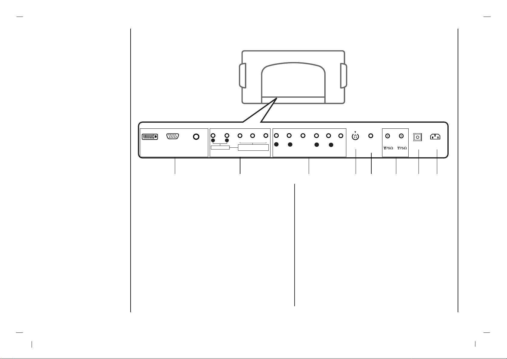
10
AUDIO INPUT
DVI INPUT
AUDIO INPUTAUDIO INPUT
R L
COMPONENT COMPONENT INPUT INPUT
(480i/480p/720p/1080i)(480i/480p/720p/1080i)
Y PbP
r
S-VIDEO SERVICE
ONLY
ANTANT 1
ANTANT 2
AC INPUT
RGB INPUTRGB INPUT
OPTICAL
AV1V1
VIDEOVIDEO
AUDIOAUDIO
L
R
AV2V2
VIDEOVIDEO
AUDIOAUDIO
L
R
1 2 3 654 7 8
1. DVI/HDMI INPUT / RGB INPUT / AUDIO INPUT
SOCKETS
Connect the set output socket of the PERSONAL
COMPUTER to this socket.
2. AUDIO INPUT / COMPONENT INPUT (480i / 480p /
720p / 1080i) SOCKETS
3. AUDIO/VIDEO SOCKET
Connect the audio/video out sockets of the VCR to AV
sockets of the set
4. S-VIDEO INPUT
Connect video out from an S-VIDEO VCR to the SVIDEO input.
5. SERVICE ONLY SOCKET
6. Antenna INPUT
7. Digital Audio (OPTICAL)
Connect digital audio from various types of equipment.
Note : In standby mode, these ports will not work.
8. POWER CORD SOCKET
This set operates on an AC power. The voltage is indicated on the Specifications page. Never attempt to
operate the set on DC power.
Location and function of controls
Back panel
11
EN
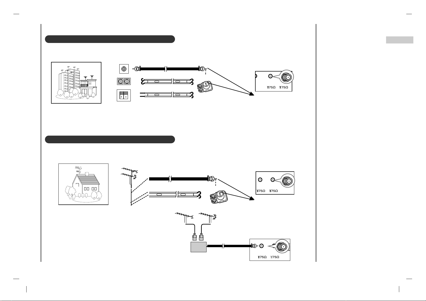
Connection to External equipment
Connecting to an Inside Antenna Setup
Connecting to an Outdoor Antenna Setup
- If you have a 75 round cable, insert the bronze wire and then tighten the connection nut. If you have a 300 flat wire, connect the twisted wire to the antenna converter and then connect the converter to the antenna jack on the TV.
- If using 75 round cable, do not bend the bronze wire. It may cause poor picture quality.
Wall Connection Jack
Apartment Buildings
Antenna Jack
Bronze Wire
Turn clockwise to tighten.
Antenna
Converter
300 Flat Wire
75 Round Cable
L ONLY
ANT 1
ANT 2
AC INPUT
OPTICAL
Antenna Jack
ANT 1
ANT 2
AC INPUT
OPTICAL
AC INPUT
OPTICAL
UHF
Antenna
VHF Antenna
- In poor signal areas, to get better picture quality,
install a signal amplifier to the antenna as shown to
the right.
- If signal needs to be split for two TVs, use an
antenna signal splitter for connection.
Signal
Amplifier
UHF
VHF
Single Family Home
Bronze Wire
Turn clockwise to tighten.
Antenna Converter
300 Flat Wire
75 Round Cable
- This type of antenna is commonly used in single family dwellings.
- Typical wall antenna jack used in apartment buildings, connect the antenna cable as shown below.
(Use the correct type of antenna cable for the type of wall antenna jack.)
ANT 1
E
ANT 2
OPTI
12
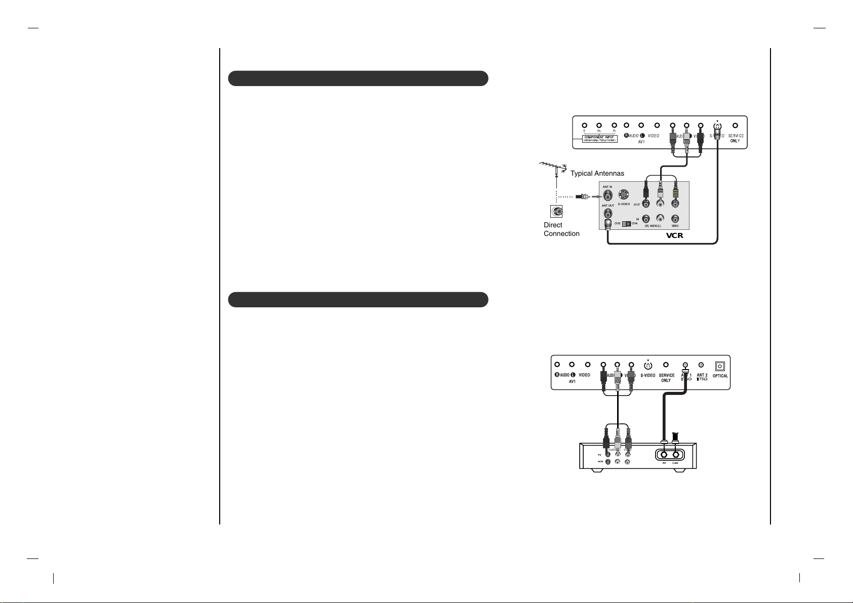
Connection to External equipment
VCR Setup
- In Video mode, TV automatically reverts to TV mode if the CH
D / E
button or number buttons are pressed.
Connection 1
Set VCR switch to 3 or 4 and then tune TV to the same channel num-
ber.
Connection 2
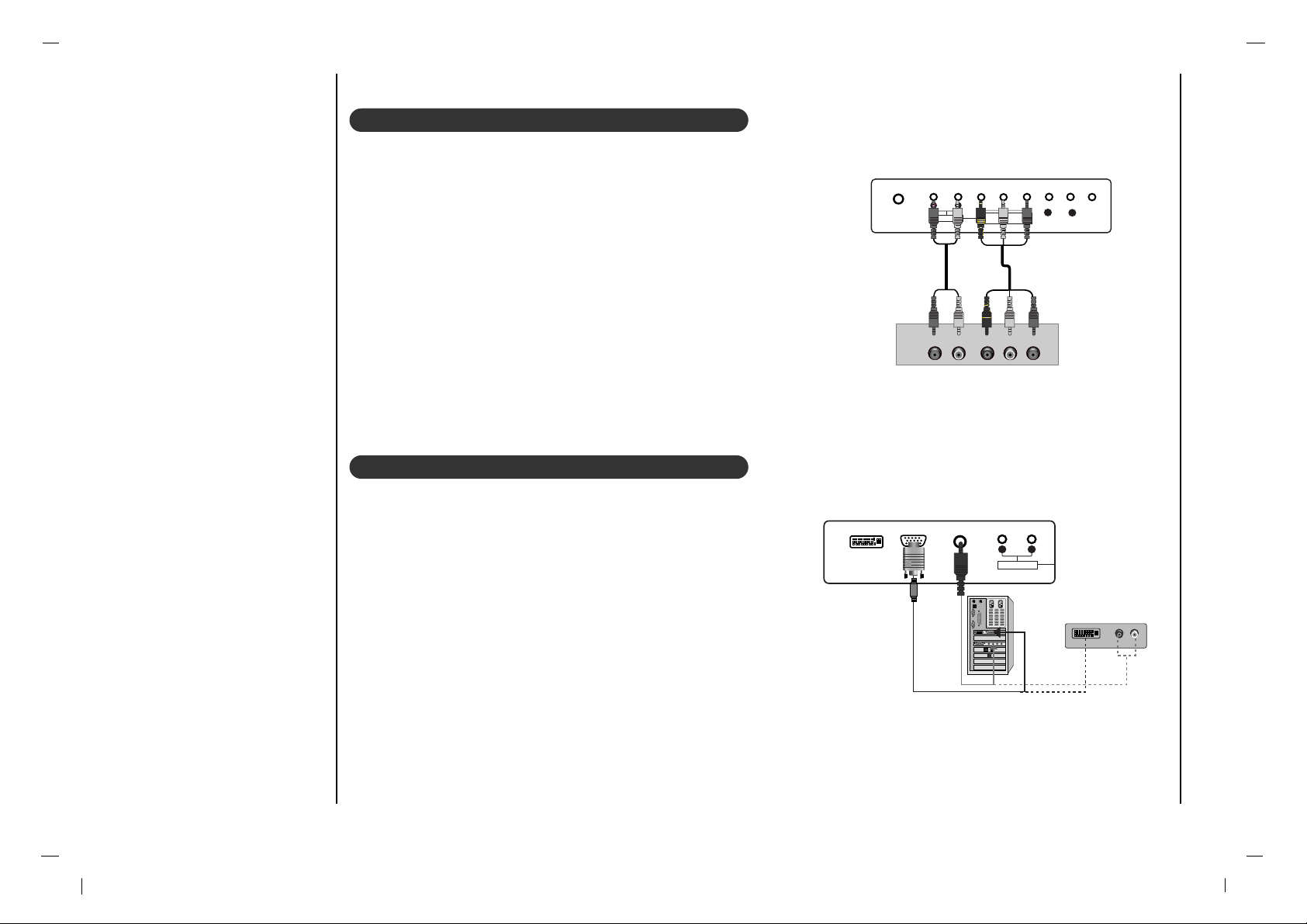
1. Connect the audio/video output jacks on VCR to the corresponding
input jacks on the TV. When connecting the TV to a VCR, match the
jack colors (Video = yellow, Audio Left = white, and Audio Right =
red).
2. Insert a video tape into the VCR and press PLAY on the VCR. (Refer
to the VCR owner’s manual.)
3. Use the INPUT SELECT button on the remote control to select AV1
or AV2. (If connected to S-VIDEO on side panel, select the S-Video
external input source.)
Cable TV Setup
- After subscribing to a local cable TV service and installing a converter,
you can watch cable TV programming.
- For further cable TV information, contact a local cable service provider.
Connection 1
1. Select 3 or 4 with channel switch on cable box.
2. Tune the TV channel to the same selected output channel of cable box.
3. Select channels at the cable box or with the cable box remote control.
Connection 2
1. Connect the audio/video output jacks on Cable Box to the corre-
sponding input jacks on the TV. When connecting the TV to Cable
Box, match the jack colors
(Video = yellow, Audio Left = white, and Audio Right = red).
2. Use the INPUT SELECT button on the remote control to select AV1
or AV2.
3. Select channels with the cable box remote control.
COMPONENTCOMPONENT INPUTINPUT
(480i/480p/720p/1080i)
Y PbP
r
S-VIDEO SERVICE
ONL
ONLY
AV1
VIDEO
AUDIO
L
R
AV2
VIDEO
AUDIO
L
R
OUT
IN
CH3 CH4
S-VIDEO
ANT IN
ANT OUT
(R) (L)
AUDIO VIDEO
Typical Antennas
VCR
Direct
Connection
S-VIDEO SERSERVICE
ONLY
ANTANT 1
ANTANT 2
OPTICAL
AV1
VIDEO
AUDIOAUDIO
L
R
AV2
VIDEO
AUDIOAUDIO
L
R
TV
VCR
(R) AUDIO (L) VIDEO
RF Cable
Cable Box
13
EN
Connection to External equipment
S-VIDEOS-VIDEO SERVICE
ONL ONLY
ANTANT 1
AV1
VIDEO
AUDIOAUDIO
L
R
AV2
VIDEO
AUDIOAUDIO
L
R
RL
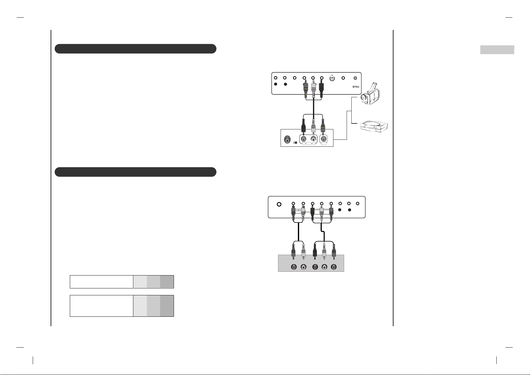
AUDIO VIDEO
External A/V Source Setup
Connections
Connect the audio/video output jacks on the external A/V equipment to
the corresponding input jacks on the TV. When connecting the TV to
external A/V equipment, match the jack colors (Video = yellow, Audio
Left = white, and Audio Right = red).
Viewing Setup
1. Turn on the external A/V equipment.
2. Use the INPUT SELECT button on the remote control to select AV1
or AV2.
3. Operate the corresponding external equipment. Refer to external
equipment operating guide.
DVD Setup
Connections
Connect the DVD video outputs to the COMPONENT (Y, PB, PR)
jacks and connect the DVD audio outputs to the AUDIO jacks.
Viewing Setup
1. Turn on the DVD player, insert a DVD.
2. Use the INPUT SELECT button on the remote control to select
COMPONENT.
3. Refer to the DVD player's manual for operating instructions.
Camcorder
Video Game set
External Equipment
Component ports
of the TV
Y PB
PR
Video output ports
of DVD player
Y
Y
Y
Y
Pb
B-Y
Cb
PB
Pr
R-Y
Cr
PR
• Component Input ports
To get better picture quality, connect a DVD player to
the component input ports as shown below.
DVD
AUDIO INPUT
AUDIO INPUTAUDIO INPUT
AUDIOAUDIO
R L
COMPONENT COMPONENT INPUT INPUT
(480i/480p/720p/1080i)(480i/480p/720p/1080i)
Y PbP
r
AV1
VIDEO
AUDIOAUDIO
L
R
AUDIO Y PB PR(L)
(R)
14
Connection to External equipment
DTV Setup
- To watch digitally broadcast programs, purchase and connect a digital set-top box.
Connections
Connect the digital set-top box video outputs to the COMPONENT
(Y, PB, PR) jacks and connect the digital set-top box audio outputs
to the AUDIO jacks.
Viewing Setup
1. Turn on the digital set-top box. (Refer to the owner’s manual for the
digital set-top box.)
2. Use the INPUT SELECT button on the remote control to select
COMPONENT.
PC (DTV) Setup
Connect the signal cable from the monitor output socket of the PERSONAL COMPUTER to the RGB INPUT socket of the set.
Connect the audio cable from the PC to the AUDIO INPUT sockets of
the set.
Press the INPUT SELECT button to select PC-RGB.
Switch on the PC, and the PC screen appears on the set.
The set can be operated as the PC monitor.
AUDIO INPUT
AUDIO INPUTAUDIO INPUT
AUDIOAUDIO
R L
COMPONENT COMPONENT INPUT INPUT
(480i/480p/720p/1080i)(480i/480p/720p/1080i)
Y PbP
r
AV1
VIDEO
AUDIOAUDIO
L
R
AUDIO Y PB PR(L)
(R)
DTV Receiver (Set-top Box)
DVI INPUT
AUDIO INPUT
AUDIO INPUTAUDIO INPUT
AUDIOAUDIO
R L
RGB INPUT
DVI INPUT
(R) AUDIO (L)AUDIO (L)
or
15
EN
Connection to External equipment
DVI (DTV)
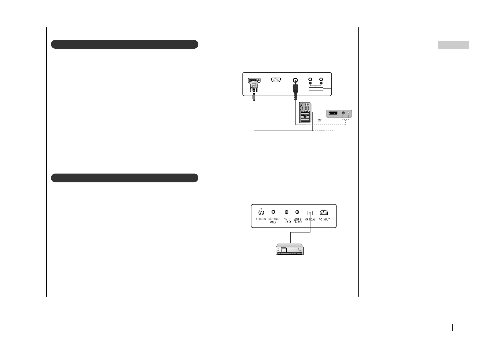
Connect the signal cable from the monitor output socket of the PERSONAL
COMPUTER to the DVI INPUT socket of the set.
Connect the audio cable from the PC to the AUDIO INPUT sockets of the set.
Press the INPUT SELECT button to select
DVI.
Switch on the DVI, and the DVI screen appears on the set.
DVI-DTV input signal : 480p-60Hz, 576p-50Hz, 720p-50Hz, 720p-60Hz,
1080i-50Hz, 1080i-60Hz.
DVI Interface with HDCP Copy Protection enables all-digital rendering of
video without the losses.
This TV SET can receive the High-Definition Multimedia Interface(HDMI) or
Input of Digital Visual Interface (DVI).
Digital Audio
- Send the set’s audio to external audio equipment (stereo system) via the
Digital Audio Output (Optical)
Caution : Do not look into the optical output port. Looking at the laser beam
may damage your vision.
How to connect
Connect one end of an optical cable to the TV Digital Audio (Optical) Output
port.
Connect the other end of the optical cable to the digital audio (optical) input
on the audio equipment.
Note : Digital Audio Output works, when it’s inputted HDMI, ATSC signal to
the set.
DVI INPUT
AUDIO INPUT
AUDIO INPUTAUDIO INPUT
AUDIOAUDIO
R L
RGB INPUT
DVI INPUTDVI INPUT
(R) (R) AUDIO (L)AUDIO (L)
S-VIDEO SERVICE
ONL
ONLY
ANT 11
ANT 22
AC INPUTAC INPUT
OPTICAL
or

16
Basic operation
Press the F / G button to adjust
the volume.
If you want to switch the sound
off, press the MUTE button.
You can cancel it by pressing
the MUTE, F / G, SSM or I/II
button.
You can select a channel number with the
D / E
or NUMBER
buttons.
Press the main power button to switch
the set on.
If the set is in standby mode, press the
POWER,
D / E
on the remote control
handset to switch it on fully.
Press the POWER button on the remote
control handset.
The set reverts to standby mode.
Press the main power button again to
switch the set off.
(Refer to p. 9)
1
1
On and Off
2
2
Channel selection
3
3
Volume adjustment
Press the MENU button and then use
D / E
button to select the SETUP
menu.
Press the G button and then use
D / E
button to select Menu Language.
Press the G button and then use
D / E
button to select your desired language.
All the on screen displays will appear in
the selected language.
Repeatedly press the MENU button to
return to normal TV viewing.
4
4
On screen language selection
(option)

On screen menus
Menu selection
17
EN
- The dialogue between you and your set takes place on screen with an operator menu. The buttons required for the
operating steps are also displayed.
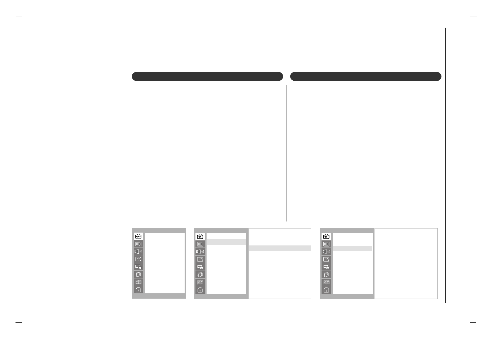
Press the MENU button and then use
D / E
button to display each menu.
Press the G button and then use
D / E
but-
ton to select a menu item.
1
1
2
2
Press the G button to display the sub menu or the pull-down menu.
Change the setting of an item in the sub or pull-down menu with F / G or
D / E
.
You can move to the higher level menu with F button and to move to the
lower level menu press the G button.
Note : Menus may vary according to input mode.
STATION
DE
F G
OK MENU
Auto
Manual
Favorite Ch.
PICTURE
DE
F G
OK MENU
CSM
PSM
Contrast
Brightness
Color
Sharpness
Tint
SOUND
DE
F G
OK MENU
SSM
Balance
AVL
SPDIF Format
TIME
DE
F G
OK MENU
Clock
Off Time
On Time
Auto Sleep
Time Zone
PIP
DE
F G
OK MENU
Mode
Input
ARC
Position
Audio Input
SETUP
DE
F G
OK MENU
Menu Language
PC Control
WXGA
VGA
Input
Child Lock
CAPTION
DE
F G
OK MENU
Caption On/Off
Analog CAP/TXT
DTV CAP Setup
DTV CAP Color
LOCK
DE
F G
OK MENU
Lock On/Off
Set Password
MPAA
Age Block
Content Block
Aux. Block
Canadian

Setting up TV stations
18
STATION
DE
F G
OK MENU
Auto
Manual
Favorite Ch.
Antenna Connection F 1 G
Digital Cable F ALL G
Search GGG
Memorizing the Channels with Auto
- For Auto to work, the programming source must be connected to the TV and the TV must be receiving programming signals either over-the-air or from a cable-type service provider.
Press the MENU button and then use
D / E
button
to select the Station menu.
Press the G button and then use
D / E
button to
select Auto.
Press the G button and then use
D / E
button to
select Antenna Connection.
Press the F / G button to select 1, 2, 3, 4.
Press the
D / E
button to select Digital Cable.
Press the F / G button to select ALL, STD, IRC, HRC.
Press the
D / E
button to select Search.
Press the G button to begin the channel search.
• Wait for auto program to complete the channel search cycle
before choosing a channel. The TV scans for over-the-air
channels and then channels provided by a cable service.
The message “ Search DTV channel? ” will appear. If you want
to search DTV select OK or G. Otherwise select MENU.
NOTES
• When the channel search is complete, use the
D/ E
buttons to review the memorized channels.
• If you press the MENU button in Auto, the function will stop and only channels programming up to that time will remain.
• Auto function can memorize only the channels which are being received at that time.
Auto
Antenna Connection F 1 G
STATION
DE
F G
OK MENU
Auto
Manual
Favorite Ch.
Antenna Connection F 1 G
Digital Cable F ALL G
Search GGG
CATV 126
0 50 %
STOP-MENU
Search DTV channel?
GGG
Auto
Search GGG
STATION
DE
F G
OK MENU
Auto
Manual
Favorite Ch.
Analog
Digital
ANT1 ANT2

19
EN
Setting up TV stations
Press the
D / E
button to select Storage.
Press the F / G button to select Memory (add) or Erase
(delete).
Repeatedly press the MENU button to return to normal TV
viewing.
The current channel is added to Memory or Erased from
the channel list.
Add/Delete Channels with Manual
- You can manually include or erase individual channels.
Press the MENU button and then use
D / E
button to
select the Station menu.
Press the G button and then use
D / E
button to select
Manual.
Press the G button and then use
D / E
button to select
Channel.
Press the F / G button to select the programme.
STATION
DE
F G
OK MENU
Auto
Manual
Favorite Ch.
Channel DTV 6-1
Storage Memory
Fine 0
BOOSTER On
Manual
Channel DTV 6-1
STATION
DE
F G
OK MENU
Auto
Manual
Favorite Ch.
Channel DTV 6-1
Storage Memory
Fine 0
BOOSTER On
Manual
Storage Memory
STATION
DE
F G
OK MENU
Auto
Manual
Favorite Ch.
20
Setting up TV stations
Fine Tuning Adjustment / BOOSTER
- This function adjusts the pictures stability and condition
when it is poor.
Press the MENU button and then use
D / E
button to
select the Station menu.
Press the G button and then use
D / E
button to select
Manual.
Press the G button and then use
D / E
button to select
Fine.
Use the F / G button to adjust the picture to your preference.
Press the G button and then use
D / E
button to select
BOOSTER.
Press the F / G button to select On or Off.
Repeatedly press the MENU button to return to normal
TV viewing.
Favorite Channels Setup
- Favorite Channel lets you quickly tune in up to 5 channels of your choice without having to wait for the TV to
scan through all the in-between channels.
Press the MENU button and then use
D / E
button to
select the Station menu.
Press the G button and then use
D / E
button to select
Favorite Ch..
Press the G button and then use
D / E
button to select the
channel.
Press the OK button to save.
Repeatedly press the FCR button to select stored favorite
channel.
STATION
DE
F G
OK MENU
Auto
Manual
Favorite Ch.
Channel 6-1
Storage Memory
Fine
GGG + 1
BOOSTER Off
Manual
Fine GGG + 1
STATION
DE
F G
OK MENU
Auto
Manual
Favorite Ch.
--CATV 14-0
DTV 14-1
CADTV 23-80
TV 20-0
TV 25-0
CATV 15-0
TV 0
TV 0
--0 : Erase
Favorite Ch.
STATION
DE
F G
OK MENU
Auto
Manual
Favorite Ch.

21
EN
Picture adjustment
Cool
Warm
Normal
User
G
To initialize values (reset to default settings), select the
Normal option.
Press the MENU button and then
D / E
button to select the
PICTURE menu.
Press the G button and then
D / E
button to select CSM.
Press the G button and then
D / E
button to select the
desired colour temperature.
Press the MENU button to save.
CSM (Colour Status Memory)
PICTURE
DE
F G
OK MENU
CSM
PSM
Contrast
Brightness
Color
Sharpness
Tint
CSM
RED 50
GREEN 50
BLUE 50
PICTURE
DE
F G
OK MENU
CSM
PSM
Contrast
Brightness
Color
Sharpness
Tint
CSM
User
G
You can adjust red, green, or blue to any colour temperature you prefer.
Press the MENU button and then use
D / E
button to
select the PICTURE menu.
Press the G button and then use
D / E
button to select
CSM.
Press the G button and then use
D / E
button to select
User.
Press the G button and then use D / E / F / G button to
make appropriate adjustments.
Repeatedly press the MENU button to return to normal TV
viewing.
PICTURE
DE
F G
OK MENU
CSM
PSM
Contrast
Brightness
Color
Sharpness
Tint

22
Picture Menu
Press the MENU button and then use
D / E
button to
select the PICTURE menu.
Press the G button and then use
D / E
button to select
the desired picture option.
Press the G button and then use F / G button to make
appropriate adjustments.
You can adjust picture contrast, brightness, colour, sharpness and tint to the levels you prefer.
Press the MENU button and then use
D / E
button to
select the PICTURE menu.
Press the G button and then use
D / E
button to select
PSM.
Press the G button and then use
D / E
button to select a
picture setting on the PSM pull-down menu.
Repeatedly press the MENU button to return to normal TV
viewing.
You can also recall a desired picture (Dynamic,
Standard, Mild, Game or User) with PSM button on
the remote control. The picture Dynamic, Standard,
Mild and Game are programmed for good picture repro-
duction at the factory and cannot be changed.
PSM (Picture Status Memory)
Manual Picture Control
Dynamic
Standard
Mild
Game
User
PICTURE
DE
F G
OK MENU
CSM
PSM
Contrast
Brightness
Color
Sharpness
Tint
PSM
Contrast 85
PICTURE
DE
F G
OK MENU
CSM
PSM
Contrast
Brightness
Color
Sharpness
Tint
Contrast
User
PICTURE
DE
F G
OK MENU
CSM
PSM
Contrast
Brightness
Color
Sharpness
Tint
23
EN
Picture Menu
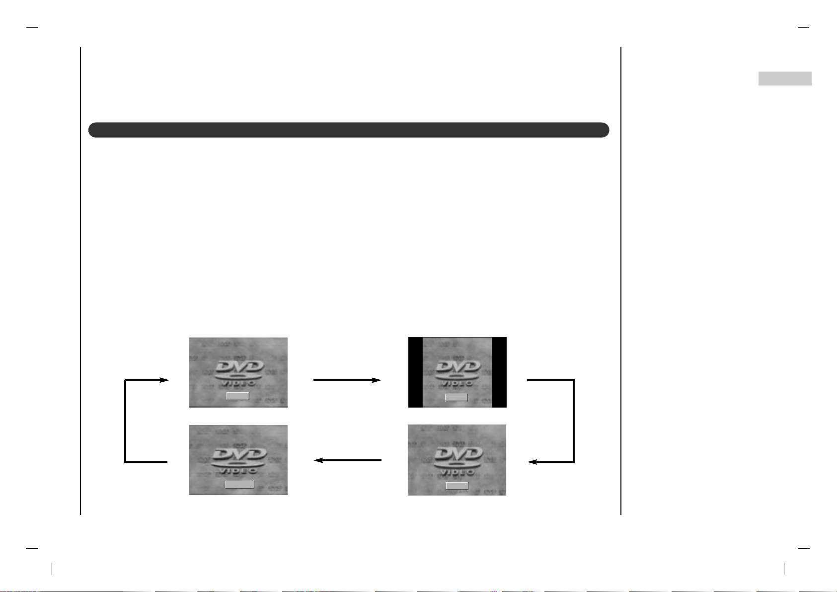
You can watch TV in various picture formats; 16:9, 4:3, ZOOM, PANORAMA.
Repeatedly press the ARC button to select your desired picture format.
1. Press the ARC button to select a desired picture format.
• Each press of ARC button changes the screen display as shown below.
• You can only select 16:9, 4:3 in PC-RGB / DVI / ATSC mode only.
Picture format
16 : 9
4 : 3
PANORAMA
ZOOM

24
Sound Menu
Sound Frequency Adjustment
a. Press the G button in User.
b. Select a sound band by pressing the
F / G button.
c. Make appropriate sound level with
the D / E button.
d. Press the OK button to store it for the
sound User.
Press the MENU button and then
use
D / E
button to select the
SOUND menu.
Press the G button and then use
D / E
button to select SSM.
Press the G button and then use
D / E
button to select a sound
setting on the SSM pull-down
menu.
Repeatedly press the MENU but-
ton to return to normal TV viewing.
SSM (Sound Status Memory)
You can also recall a desired sound
(Flat, Speech, Movie, Music or
User) with SSM button on the remote
control. The sound Flat, Speech,
Movie and Music are programmed for
good sound reproduction at the factory
and cannot be changed.
DE
F G
OK MENU
0.1 0.5 1 5 10kHz
Flat
Speech
Movie
Music
User
G
SOUND
DE
F G
OK MENU
SSM
Balance
AVL
SPDIF Format
SSM
User G
SOUND
DE
F G
OK MENU
SSM
Balance
AVL
SPDIF Format

25
EN
Sound Menu
L 0 R
SOUND
DE
F G
OK MENU
SSM
Balance
AVL
SPDIF Format
Balance
On
Off
SOUND
DE
F G
OK MENU
SSM
Balance
AVL
SPDIF Format
AVL
Press the MENU button and then use
D / E
button to
select the SOUND menu.
Press the G button and then use
D / E
button to select the
desired sound item.
Press the G button and then use F / G button to make
appropriate adjustments.
Repeatedly press the MENU button to return to normal TV
viewing.
Press the MENU button and then use
D / E
button to
select the SOUND menu.
Press the G button and then use
D / E
button to select
AV L .
Press the G button and then use
D / E
button to select
On or Off.
Repeatedly press the MENU button to return to normal TV
viewing.
This feature maintains an equal volume level; even if you
change channels.
AVL (Auto Volume Leveler)
Balance
SOUND
DE
F G
OK MENU
SSM
Balance
AVL
SPDIF Format

26
Sound Menu
SPDIF Format
Press the MENU button and then use
D / E
button to
select the SOUND menu.
Press the G button and then use
D / E
button to select
SPDIF Format.
Press the G button and then use
D / E
button to select
AC-3 or PCM.
Repeatedly press the MENU button to return to normal
TV viewing.
AC-3
PCM
SOUND
DE
F G
OK MENU
SSM
Balance
AVL
SPDIF Format
SPDIF Format
SOUND
DE
F G
OK MENU
SSM
Balance
AVL
SPDIF Format
Note :
a : It’s available to use AC-3 or PCM in Dolby Digital
Audio signal.
b : When it doesn’t apply the Dolby Digital Audio signal,
select the PCM function to output the dolby digital
audio by SPDIF output.

Sound Menu
27
EN
• Press the I/II button repeatedly.
- Select mono sound mode if the signal is not clear or in poor signal reception areas.
- Stereo, SAP mode are available only if included on the broadcast signal.
• Press the I/II button repeatedly.
- This function lets you select your preferred language for audio.
- If the audio data in selected language is not broadcasted, the supported audio will be played.
- If other languages available on the digital signal, select them with the I/II button.
- The broadcast supported audio language will be appear in turn.
- The TV can receive MTS stereo programs and any SAP (Secondary Audio Program) that accompanies the stereo program, if the broadcaster transmits an additional sound signal as well as the original one.
- Mono: The primary language is heard from left and right speakers. Signal mode is mono.
- Stereo: The primary language is heard from left and right speakers. Signal mode is stereo.
- SAP: The secondary language is heard from left and right speakers.
Stereo/SAP Broadcasts Setup
Audio Language (in digital mode only)
SAP Stereo Mono

Time Menu
28
D
Auto
E
02:37 AM
TIME
DE
F G
OK MENU
Clock
Off Time
On Time
Auto Sleep
Time Zone
Clock
D
Manual
E
02:37 AM
TIME
DE
F G
OK MENU
Clock
Off Time
On Time
Auto Sleep
Time Zone
Clock
[ Auto ]
- The time is set automatically from a digital channel signal.
- The digital channel signal includes information for the
current time provided by the broadcasting station.
- Set the clock manually, if the current time is set incorrectly by the auto clock function.
Press the MENU button and then
D / E
button to select
the TIME menu.
Press the G button and then
D / E
button to select
Clock.
Press the G button and then
D / E
button to select Auto.
Repeatedly press the MENU button to return to normal TV
viewing.
[ Manual ]
- If current time setting is wrong, reset the clock manually.
Press the MENU button and then
D / E
button to select
the TIME menu.
Press the G button and then
D / E
button to select Clock.
Press the G button and then
D / E
button to adjust the
hour.
Press the G button and then
D / E
button to adjust the
minute.
Repeatedly press the MENU button to return to normal TV
viewing.
Clock
TIME
DE
F G
OK MENU
Clock
Off Time
On Time
Auto Sleep
Time Zone

29EN29
Time Menu
The off timer automatically switches the set to standby at
the preset time.
Press the MENU button and then
D / E
button to select
the TIME menu.
Press the G button and then
D / E
button to select Off
Time
or On Time.
Press the G button and then
D / E
button to select On.
To cancel Off/On Time function, press the
D / E
button
to select Off.
Press the G button and then
D / E
button to adjust the
hour.
Press the G button and then
D / E
button to adjust the
minute.
Only On time function; Press the G button and then
D / E
button to adjust volume level and programe number.
Repeatedly press the MENU button to return to normal TV
viewing.
Note :
a.In the event of power interruption (disconnection or power
failure), the clock must be reset.
b.T wo hours after the set is switched on by the on time func-
tion it will automatically switch back to standby mode
unless a button has been pressed.
c.Once the on or off time is set, these functions operate
daily at the preset time.
d.Off Timer function overrides On Timer function if they are
set to the same time.
e.The set must be in standby mode for the On Timer to
work.
On/Off Time
06:59 AM
CH. CATV 14
VOL. 46
On
TIME
DE
F G
OK MENU
Clock
Off Time
On Time
Auto Sleep
Time Zone
On Time
TIME
DE
F G
OK MENU
Clock
Off Time
On Time
Auto Sleep
Time Zone

30
If you select On on the Auto Sleep menu, the set will
automatically switch itself to standby mode approximately
ten minutes after a TV station stops broadcasting.
Press the MENU button and then
D / E
button to select the
TIME menu.
Press the G button and then
D / E
button to select Auto
Sleep
.
Press the G button and then
D / E
button to select On or
Off.
Repeatedly press the MENU button to return to normal TV
viewing.
Auto sleep
Time Zone
Press the MENU button and then
D / E
button to select
the TIME menu.
Press the G button and then
D / E
button to select Time
Zone
.
Press the G button and then
D / E
button to select your
viewing area time zone : Eastern, Central, Mountain,
Pacific.
Repeatedly press the MENU button to return to normal TV
viewing.
On
Off
TIME
DE
F G
OK MENU
Clock
Off Time
On Time
Auto Sleep
Time Zone
Auto Sleep
Eastern
Central
Mountain
Pacific
TIME
DE
F G
OK MENU
Clock
Off Time
On Time
Auto Sleep
Time Zone
Time Zone
TIME
DE
F G
OK MENU
Clock
Off Time
On Time
Auto Sleep
Time Zone
Time Menu

31
EN
Time Menu
Sleep timer
You don’t have to remember to switch the set off before you go to sleep. The sleep timer automatically switches the
set to standby after the preset time has elapsed.
Press the SLEEP button to select the number of minutes. The display ‘’will appear on the screen, followed
by 10, 20, 30, 60, 90, 120, 180 and 240. The timer begins to count down from the number of minutes selected.
Note :
a.To view the remaining sleep time, press the SLEEP button once.
b.To cancel the sleep time, repeatedly press the SLEEP button until the display ‘ ’ appears.
c.When you switch the set off, the set releases the preset sleep time.
- - - min
- - - min

32
SETUP
DE
F G
OK MENU
Menu Language
PC Control
WXGA
VGA
Input
Child Lock
Child lock
The TV can be set so that the remote control handset is
needed to control it. This feature can be used to prevent
unauthorized viewing.
Press the MENU button and then
D / E
button to select
the Setup menu.
Press the G button and then
D / E
button to select Child
lock
.
Press the G button and then
D / E
button to select On or
Off.
Repeatedly press the MENU button to return to normal TV
viewing.
With the lock on, the display Child lock on appears on
the screen if any button on the side panel is pressed while
viewing the TV.
Note : The display Child lock on will not appear on the
screen if any button on the panel is pressed while displaying the menus.
On
Off
SETUP
DE
F G
OK MENU
Menu Language
PC Control
WXGA
VGA
Input
Child Lock
Child Lock
Setup Menu

33
EN
Caption Menu
Use the CC button repeatedly to select Captions.
EZ Mute shows the selected captions option (if available
on program) when the TV sound is muted.
Press the MENU button and then use
D / E
button to
select the Caption menu.
Press the G button and then use
D / E
button to select
Caption On/Off.
Press the G button and then use
D / E
button to select
Off,On or Ez Mute.
Press the MENU or OK button to save.
Note : It’s not available in Component and RGB-PC
modes.
Caption On/Off
Press the MENU button and then use D / E button to
select the Caption menu.
Press the G button and then use D / E button to select
Analog CAP/TXT.
Use the D / E button to select your caption selection. Your
choices are : CC1, CC2, CC3, CC4, Text 1, Text 2,
Text3
and Text4.
Press the EXIT button to save and return to TV viewing.
Analog CAP/TXT
Off
Ez Mute
On
CAPTION
DE
F G
OK MENU
Caption On/Off
Analog CAP/TXT
DTV CAP Setup
DTV CAP Color
Caption On/Off
D CC1 E
CAPTION
DE
F G
OK MENU
Caption On/Off
Analog CAP/TXT
DTV CAP Setup
DTV CAP Color
Analog CAP/TXT
CAPTION
DE
F G
OK MENU
Caption On/Off
Analog CAP/TXT
DTV CAP Setup
DTV CAP Color

34
Press the MENU button and then use
D / E
button to
select the Caption menu.
Press the G button and then use
D / E
button to select
DTV CAP Setup.
Press the G button and then use
D / E
button to select
Service, Font By, Font Size or Font Style.
Press the F / G button to make appropriate adjustments.
Repeatedly press the MENU button to return to normal TV
viewing.
DTV CAP Setup
Press the MENU button and then use D / E button to
select the Caption menu.
Press the G button and then use D / E button to select
DTV CAP Color.
Press the G button and then
D / E
button to select the
desired font style item.
Press the F / G button to make appropriate adjustments.
Repeatedly press the MENU button to return to normal
TV viewing.
DTV CAP Color
Service F 5 G
Font By F User G
Font Size F Large G
Font Style F Font3 G
CAPTION
DE
F G
OK MENU
Caption On/Off
Analog CAP/TXT
DTV CAP Setup
DTV CAP Color
DTV CAP Setup
Fg Color F White G
Fg Opacity F Solid G
Bg Color F White G
Bg Opacity F Frash G
Edge Type F Raised G
Edge Color F White G
CAPTION
DE
F G
OK MENU
Caption On/Off
Analog CAP/TXT
DTV CAP Setup
DTV CAP Color
DTV CAP Color
CAPTION
DE
F G
OK MENU
Caption On/Off
Analog CAP/TXT
DTV CAP Setup
DTV CAP Color
Caption Menu

35
EN
Lock Menu
(option)
Parental Control can be used to block specific channels, ratings and other viewing sources.
The Parental Control Function (V-Chip) is used to block program viewing based on the ratings sent by the broadcast station. The default setting is to allow all programs to be viewed. Viewing can be blocked by the type of program and by
the categories chosen to be blocked. It is also possible to block all program viewing for a time period. To use this function, the following must be set :
1. Ratings and categories to be blocked. 2. Set a password 3. Enable the lock
V-Chip rating and categories
Rating guidelines are provided by broadcast stations. Most television programs and television movies can be blocked
by TV Rating and/or Individual Categories. Movies that have been shown at the theaters or direct-to-video movies use
the Movie Rating System (MPAA) only.
For Movies previously shown in theaters :
Movie Ratings :
• Unblocked
• G and Above
: (general audience)
• PG and Above
: (parental guidance suggested)
• PG-13 and Above
: (13 years and older))
• NC-17 and Above
: (18 years and older)
• X : (adult)
If you set PG-13 and Above : G and PG movies will be
available , PG-13, NC-17 and X will be blocked.
For Television programs including made-for-TV
movies:
General TV Ratings:
• Unblocked
• TV-G and Above
: (general audience)
: (individual categories do not apply)
• TV-PG and Above
: (parental guidance suggested)
• TV-14 and Above
: (14 years and older)
• TV-MA
: (mature audience)
Children TV Ratings:
• Unblocked
• TV-Y and Above
: (youth) (individual content categories do not apply)
• TV-Y7
: (youth, 7 years and older)
Lock Menu Options

36
Lock Menu
(option)
Content Categories:
• Dialog - sexual dialogue
: (applies to TV-PG and Above, TV-14, Unblocked)
• Language - adult language
: (applies to TV-PG and Above,TV-14 and Above,
TV-MA, Unblocked)
• Sex scenes - sexual situations
: (applies to TV-PG and Above, TV-14 and Above,
TV-MA, Unblocked)
• Violence
: (applies to TV-PG and Above, TV-14 and Above,
TV-MA, Unblocked)
• F Violence - fantasy violence
: (applies to TV-PG and Above, TV-14 and Above,
TV-MA, Unblocked)
For Canadian English/French language rating system:
Canadian English language rating system:
• C and Above
: Children)
• C8+ and Above
: (8 years and up)
• G and Above
: (General programming. Suitable for all audiences.)
• PG and Above
: (Parental guidance suggested)
• 14+and Above
:(Viewers 14 years and older)
• 18+
: (Adult programming)
• Unblocked
Canadian French language rating system:
• G (General)
• 8 ans+ (8 years and older)
• 13 ans+ (13 years and older)
• 16 ans+ (16 years and older)
• 18 ans+ (Adults only)
• Unblocked

37
EN
Lock Menu
(option)
Press the MENU button and then use
D / E
button to
select the LOCK menu.
Then, press the G button.
• If Lock is already set, enter the password requested.
• The TV is set with the initial password “0-0-0-0”.
Setting Lock on/off:
Press the
D / E
button to select Lock on/off.
Press the G button and then use D / E button to select
on or off.
Set password:
Press the
D / E
button to select Set password.
Press the G button and then enter a four digit password.
Enter it again when requested.
Press the
D / E
button to select type of blocking to be set.
Press the G button and then use
D / E
button to select
type of ratings to block .
• Age block, Content block, and Canadian
menus, also have sub menus. So, repeat steps 4 and
5 in the sub menu, to set the types of blocking and ratings.
Lock Menu Setup
On
Off
LOCK
DE
F G
OK MENU
Lock On/Off
Set Password
MPAA
Age Block
Content Block
Aux. Block
Canadian
Lock On/Off
New ----
Confirm ----
LOCK
DE
F G
OK MENU
Lock On/Off
Set Password
MPAA
Age Block
Content Block
Aux. Block
Canadian
Set Password
LOCK
DE
F G
OK MENU
Lock On/Off
Set Password
MPAA
Age Block
Content Block
Aux. Block
Canadian

38
EPG ( Electronic Programme Guide)
/ Information
- This function can be used only when the EPG information is broadcasted by broadcasting companies.
- This system has an Electronic Programme Guide (EPG) to help your
navigation through all the possible viewing options.
- The EPG supplies information such as programme listings, start and
end times for all available services.
- In addition, detailed information about the programme is often available in the EPG (the availability and amount of these programme
details will vary, depending on the particular broadcaster.)
EPG ( Electronic Programme Guide)
Switch on/off EPG
Press the EPG button.
Press the EPG button to return to normal TV viewing.
Select a programme
Press the
D / E
button to select desired programme.
Press the F / G button to select a programme time.
Press the OK button to display the selected programme.
- This function shows the present screen
information.
Press the INFO button during watching TV.
The service information appears on screen.
Press the INFO or MENU button to exit.
Note :
a When you press the OK button, Signal
Strength
aren’t displayed on the infor-
mation OSD.
b It’s disappeared after a while.
Information
03:15 am ~ 03:20 am
ABC Friday, 22. July. 2005
03:15 am
03:20 am
03:30 am
03:45 am
04:00 am
04:15 am
News Parade
Live Broadcasting Today (part1-3
Pz’s Morning part1
PJK News
Come to Papa
Stephen King’s ‘Kingdom Hospital’
7-1 ABC
No CC Not Rated
Signal Strength
Multi

39
EN
RGB-PC Menu
You can adjust horizontal/vertical position, clock, phase,
and auto-configure, reset as you prefer.
Press the MENU button and then
D / E
button to select
the SETUP menu.
Press the G button and then
D / E
button to select the
desired picture item.
Press the F / G button to make appropriate adjustments.
H-Position / V-Position
This function is to adjust picture to left/right and up/down
as you prefer.
Clock
This function is to minimize any vertical bars or stripes visible on the screen background. And the horizontal screen
size will also change.
Phase
This function allows you to remove any horizontal noise
and clear or sharpen the image of characters.
Auto-configure
This function is for the automatic adjustment of the screen
position, clock and phase. The displayed image will disappear for a few seconds while the Auto-configuration is in
progress.
Reset
This function allows you to return to the good picture reproduction programmed at the factory and cannot be
changed.
Note : Some signal from some graphics boards may not
function properly. If the results are unsatisfactory, adjust
your monitor’s position, clock and phase manually.
Press the OK button to store it for the PC monitor picture.
Press the EXIT button to return to PC mode.
- When the set is inputted DVI-480p signal in VGA mode, select 480p on the SETUP menu.
- When the set is inputted WXGA signal, select the desired WXGA resolution.
WXGA (or VGA (Only RGB/DVI mode))
PC Setup
H-Pos. 0
V-Pos. 0
Clock 10
Phase 15
Auto
Reset
SETUP
DE
F G
OK MENU
Menu Language
PC Control
WXGA
VGA
Input
Child Lock
PC Control
1024X768
1280X768
1360X768
1366X768
SETUP
DE
F G
OK MENU
Menu Language
PC Control
WXGA
VGA
Input
Child Lock
WXGA
640X480
480P
SETUP
DE
F G
OK MENU
Menu Language
PC Control
WXGA
VGA
Input
Child Lock
VGA

40
Press the PIP button to show the sub picture.
• Each press of PIP button changes the screen display as
shown below.
Watching PIP
PIP Audio Input
- PIP lets you view 2 different inputs (sources) on your monitor screen at the same time. One source will be large, and
the other source will show a smaller inset image.
- PIP is not available in Lock On mode only.
Off
PIP
DW2
POP
DW1
Press the MENU button and then
D / E
button to select
the PIP menu.
Press the G button and then
D / E
button to select Audio
Input
.
Press the G button and then
D / E
button to select Main
or Sub.
Repeatedly press the MENU button to return to normal TV
viewing.
PIP mode - main and sub picture audio select.
PIP
DE
F G
OK MENU
Main
Sub
Mode
Input
ARC
Position
Audio Input
Audio Input
PIP (Picture-In-Picture) Feature

41
EN
PIP (Picture-In-Picture) Feature
Press the PIP POSITION button.
Press the PIP POSITION button repeatedly until desired
position is achieved. The sub pictures move clockwise.
Moving the PIP
Selecting a Input Signal Source for the PIP
Press the SWAPbutton to exchange the main and sub pic-
tures.
Swapping the PIP
Main Picture Sub Picture
Use the PIP INPUT button to select the input source for
the sub picture.
Press the PIP PR +/- button. The selected programme
number is displayed just below the programme number of
main picture.
Programme selection for sub picture
This function enables you to search all the stored stations
on 4 or 16 sub pictures and see your favorite station by
exchanging the main and sub pictures.
Press the SCAN button repeatedly to select
POP4/POP16.
The selected sub or main pictures search all the stored
stations.
Press the EXIT button to switch off sub or main pictures.
This function works in the following mode : TV, AV1, AV2,
S-VIDEO.
Programme scan

42
Note:
a. If the set is cold, there may be a small “flicker” when the
set is switched on. This is normal, there is nothing wrong
with the set.
b. If possible, use the VESA 1,280x1,024@60Hz video
mode to obtain the best image quality for your LCD monitor. If used to PC vertical frequency 85Hz, some noise
can be seen when PIP is on. In this case, set the PC vertical frequency to 60Hz. The set has been pre-adjusted
to the mode VESA 1,280x1,024@60Hz.
c. Some dot defects may appear on the screen, like Red,
Green or Blue spots. However, this will have no impact
or effect on the monitor performance.
d. Do not press the LCD screen with your finger for a long
time as this may produce some temporary distortion
effects on the screen.
e. When the PC screen appears on the set, a message
may appear on the screen, and the message will differ
according to the Window system version (Win98, 2000).
If a message appears click “Next” until the message fin-
ishes.
f. If the message “Out Of Range” appears on the screen,
adjust the PC as in the ‘Displayable Monitor
Specification’ section.
RGB Mode / DVI Mode
(Synchronization input form : separate)
Resolution
61.5
31.5
37.9
31.5
37.8
37.5
43.2
35.1
37.9
48.0
46.9
53.7
48.4
56.4
60.0
60.0
63.9
75.0
79.9
91.1
47.7
60.1
68.5
49.0
49.0
75.0
49.7
640X350
720X400
640X480
800X600
1024X768
1280X1024
1280X768
1360X768
1366X768
1600X1200
832X624
MODE
DOS
VGA
SVGA
XGA
SXGA
WXGA
UXGA
MAC
Horizontal
Frequency (KHz)
70.0
70.0
85.0
60.0
72.0
75.0
85.0
56.0
60.0
72.0
75.0
85.0
60.0
70.0
75.0
85.0
60.0
70.0
75.0
85.0
60.0
75.0
85.0
60.0
60.0
60.0
75.0
Vertical
Frequency (Hz)
Displayable Monitor
Specification

43
EN
Troubleshooting
Check list
Check these items and try to adjust these
Symptoms
No picture, no sound
Sound OK, poor picture
Picture OK, poor sound
Picture blurred
Lines or streaks in picture
Poor reception on some channels
No colour
Poor colour
Remote control does not work
Incorrect position
Vertical bars or stripes on background
Horizontal noise
Signal Cable message appears
The mains plug-(plugged in and switched on)
Is the TV switched on
Try another channel (weak signal)
Check aerial (plugged into TV?)
Check aerial (broken lead?)
Check aerial
Check for local interference
Adjust contrast
Adjust brightness
Adjust colour
Adjust volume
Check the batteries in remote control
Check Audio/Video sockets (VCR only)
Auto-configure or adjust the H/V position
Auto-configure or adjust Clock
Auto-configure or adjust Clock Phase
Is the Signal Cable connected or loose

Product Specification
Power Requirement
Power Consumption
Resolution
Colors
Viewing Angle
Luminance
Contrast Ratio
Speaker
Antenna in
Applied Tuner
AC 100 - 240V ~, 50/60Hz(Auto Switching)
240W
1366*768(dot)
16.7M
178/178(degrees)
500㏅/㎡
550:1
30W(15W+15W)
75 ohm Din jack
PAL: TAEW-W101P(LG)
NTSC: TAWE-H101P(LG)

 Loading...