

IndigoVision XP Quick Start Manual
INDIGOVISION
XP HD PTZ CAMERA
BX RANGE
QUICK START GUIDE
COPYRIGHT © INDIGOVISIONLIMITED. ALL RIGHTS RESERVED.
INDIGOVISIONIS A TRADEMARK OF INDIGOVISIONLIMITED AND IS
REGISTEREDIN CERTAIN COUNTRIES.SMS4, CAMERA GATEWAY,
ANDMOBILE CENTER ARE UNREGISTEREDTRADEMARKS OF
INDIGOVISIONLIMITED. ALL OTHER PRODUCTNAMES REFERREDTO
INT HISMANUAL ARET RADEMARKSOF THEIR RESPECTIVE OWNERS.
THIS MANUALIS PROVIDEDWITHOUT EXPRESS REPRESENTATION
AND/ORWARRANTY OF ANY KIND.
PLEASE CONTACTI NDIGOVISIONLIMITED (EITHERBY POST OR BY E-
MAILAT PARTNER.SUPPORT@INDIGOVISION.COM)WITH ANY
SUGGESTED CORRECTIONSAND/OR IMPROVEMENTST OT HIS
MANUAL.
CONTACT ADDRESS
CHARLESDARWIN HOUSE,
EDINBURGH TECHNOPOLE,
EDINBURGH, EH260PY, UK
FURTHER INFORMATION
FOR FURTHERINFORMATION, SEE THE USER GUIDE:
YOUCAN DOWNLOADA COPY FROM:
WWW.INDIGOVISION.COM/XF-HD-PTZCAMERA-QUICKSTARTGUIDE
ALTERNATIVELY, SCANTHE QRCODEBELO W.
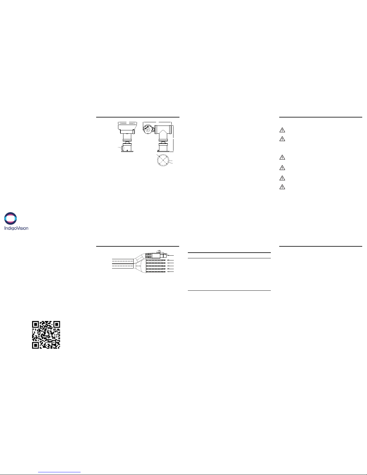
PACKAGE CONTENTS
Ø210
Ø182
M25 CA BLE
ENTRY
Ø11
512
475
334
260
Camera
• 1 xM25
• FlexibleCond uit(AT EX,IEC Exand INMET ROmod elsonly)
• Cable Bundle( UL and CSA modelsonly)
Additional items
• Sunshieldand fixings
• IndigoVisionlogo stickersfor sunshield
• Envelopecontaining ATEX Technical Manualsand wiring
diagrams
SAFETY INFORMATION
Warning
Ensure the power supplyis switched off during installation.
When installing the camera, fasten it securely to the surface. A falling
camera may causeper sonalinjury.
Caution
Onlyinstall insuitable environments. For more information, see the Atex
TechnicalManua ls.
Handle the camera with care so the mainelectronics and components
are not damaged.
For security reasons, you must change the camera's default username
and password.
Ensure each camera hasa unique IPaddress.
Notices
Use only hex socket head fasteners with property class of A4-7 0
for securing end coversand shafts to housing.
Read thisgu idebefor einstalling the camera.
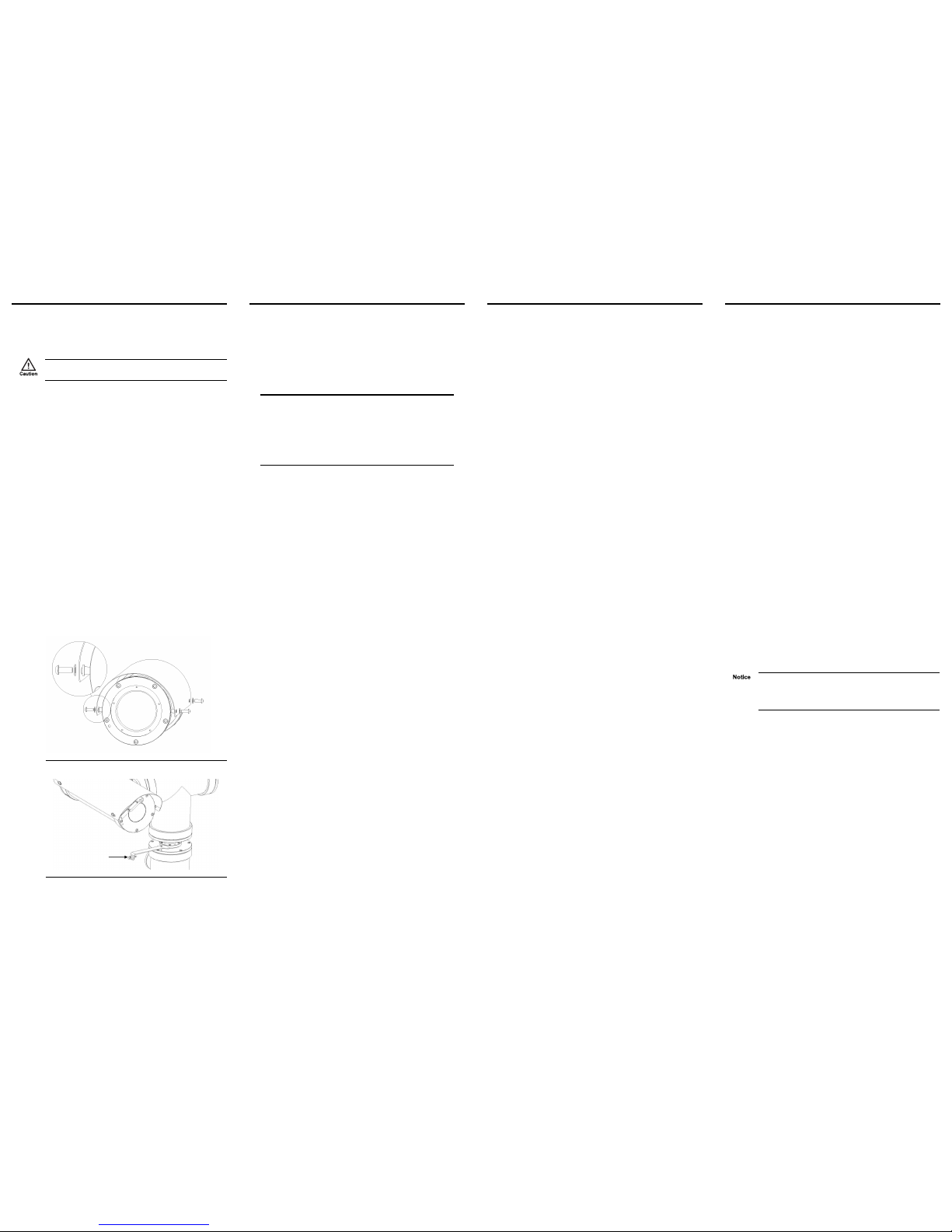
CONNECTIONS
1
2
3
4
5
6
Pin connections
Pin nu mber Type Descriptio n
1 CAT5 Multicore Ethernet connection
2 Green/Yellow Earth
3 Blue 24V AC (120W/5A) Common
4 Brown 24V AC (120W/5A) Live
5 Violet 24V AC Outputfo r water pump
6 Yellow 24VAC Pump Common
Document ID: IU-PTZ -MAN014-1
REGULATORY
Regulatory information is marked on the silver reg ulatory label
applied to r ear face of the camera. The regulatory approvals
appliedto the camera include one or more of the following
standards:
• EN60079-14:2008
• IEC60079-14:2007
• UL1203 (2006)
• UL 60065 (Edition 7)
• CAN/CSA-22.2 No 60065- 03( 2012)
• CAN/CSA-22.2 No 30 M1986 (2012 )
• CAN/CSA-22.2 No 25-1 966( 2009)
• INMETRO
• No modificationsmust be made to the flamepaths ofth eunit
without consultationof the drawings listed.
• Temperatur escould exceed 700C at the cablegland or 800C
at the branching point,suitably rate cable mustbe selected.
• No electromagnetic or ultrasonicradiating equipment to be
fitted intothe enclosures. However, a fibre optic transmitter
may bef itted,the output fr omw hichmust always be routed
out of the enclosurevia armoured cable or conduit and must
be terminated within asuitably certified enclosureor in a safe
area.
• A routine overpressure test inaccordance with IEC 600791:2007 Clause 16.1 shallbe carried out on allen closures,
Includingall cemented window assemblies,at a pressure of
27.3 Bar for a period of between 10 and 60 secondsand must
be recorded. There shall be no deformation or damage to the
enclosuresand no leakage through the cement of any of the
window assemblies.
1. POWERING UP THE CAMERA
The camera power req uirements are 24V AC (±10%) with a
maximum power of 120 Watts.
The camera should only be power ed from the specified voltage.
No allowanceis made for a varying voltagesupply.
Applyingthe incorrect power supplyvoltage will causeir reparable
damage to the unit.
Figure 1 Sunshieldinstallation
Figure 2 Washer nozzleinstallation
2. CONFIGURING THE CAMERA
Before you connect the camer a to your networ k, you must
configure the camera's IPaddressand subnet mask
appropriately.
Configure the network settings
1. Connectt hecamer a toa PC using an Ethernet crossover
cable.
2. Navigateto the camera's default IP address usinga web
browser, and enter the default user name and password.
Default Username Admin
Default Password 1234
Default IP Address 10.5.1 .10
Default Subnet Mask 255.0.0.0
Default Gateway 10.0.0.1
3. Enter the NTP server on the Date & Time menu.
4. Enter a new IPaddr essand subnet mask on the Network
menu.
Configure the serial port
The camera is configured bydefau lt to appear as a PTZ camera
within Control Center.
The serial communications between the internal camera and the
enclosure isconfigured as RS485 PelcoD at2400bp s. The serial
port controls the Wash/Wipe and Pan/Tilt functions within the
ATEX enclosure.
Configure the Wipe and Wash
By default Wipe and Wash commands are saved as Presets 86
(Wipe) and 87 ( Wash). T hese appear in C ontrol Center as the
first two Presets available. If these Presets are deleted or
overwritten they can be r estored by accessing the Preset section
on the camera configuration page.
The wiper is configured tow ipefor 3 wipes then automaticallystop
on RECALL of Preset 86.
On RECALL of Preset 87 the switched output ( Wash) willactivate
for 5 seconds.
3. INSTALLATION
Sunshield install ation
The sunshield issupplied uninstalled to pr event damage during
shippingand unpacking. They are supplied with a protective white
filmthat must be removed prior to installation.
To mount the sunshield, position it correctly and fix with a nylon
spacer between the sunshield and the camera housing. The M6
A4 button head screws supplied must have t he red fibr e washer
fitted before fixingthe sunshield.
Washer nozzle installation
A suitable washer nozzle and mounting bracket may be fitted
during installation. T he washer nozzle should be positioned to
allowcleaning fluid to reach the camera housingwindow w henth e
wash command issent.
The wash command is configured as Preset 87 and can be saved
with a suitablename within the camera configuration pages.
Electrical installation
Electrical installation and servicing should only be carried out by
qualified service personnel and in accordance with all
local/nationalcodes of practiceand standar ds.
This guide only covers the standard installation. For de tailed
connection and configuration, refer to individual pr oject specific
drawings and information.
► For more information, refer to the ATEX TechnicalM anuals
and wiring diagrams.
• Alwaysuse color-coded conductors or other identificationof
conductors for easeo fw iringand identification.
• Keep a wiringd iagram withth esystem for later use and
reference.
• Provisionis made for one cable entry, att hebase mount of
the pan tilt.
• To maintain the certificationrequirements of the unit all
cables/conduitsmust be fitted atth eentr y,w ithcertified Exd
Flameproof, compound filled barrier glands, either brass,
nickelplated or stainlesssteel.
• The cable entry toth eunit is M25 x1 .5ISO thread, or M 20
usingan Exd certified reducer.
• A minimumof 10mm depth of engagemen tmust be
maintained for allglands.
• Allglands/reducers must be ingress protected to IP67 or
better, to maintain the weatherproof rating of the equipment.
• For maintenance purposes, consultthe separat elysupplied
additionalwiring dra wingsspecificto the unit.
4. OPERATIONS
This chapter describes common tasks r equired for the operation
of the ProductName.
Focus the camera using Control C enter
1. Addthe camera to the Contr olC enter sitedataba seensuring
you configureth eD evice Access credentials.
2. Right-clickthe camera in the Video Expl orer, select
Properties > Video an d Au dio, and selectthe appr opriate
Profile Token and Connection.
3. Right-clickthe camera in the Video Expl orera ndselect View
Video.
4. Inthe main window, clickthe Co nfigu ration tab.
5. Navigateto Video > Basic and use the Zoo mand Fo cus
optionsto focus the camera.
Configuring the camera
1. Youcan access thecamer a configurationpages using the IP
address of the camera.
Alternatively,you can accessthese pages through
IndigoVisionContr olCente r.
2. InSet up view, selectthe camera you want to configure.
3. Selectthe Con figuratio n tab, and enter a validuser name
and password.
Maintenance
• Recommended inspectioninterval - 6 months.
• Fixingsand fastenings should bechecked for tightness and
integritya tr egular intervals.
• Allcable entries and cablesshould be checkedfor integrityat
regular intervals.
• Clean the unit.
• Check the‘O’ ring weather seals and replace ifnecessary.
• Replace 'O'rings every 5 years.
• Check andif necessary replace the washer nozzle.
• Check andif necessary replace the window wiper blade.
Cameras operating in extremely harsh environmentsmay requ ire
more fr equent inspection and maintenance checks. Please read
and be familiarwith the instructions before servicingthe Pan/Tilt
or housing.
Corrision protection
Although all external metal components are produced from 316L
StainlessSteel, if the units ar e not corr ectlymaintained, hand led,
and cleaned re gularly there is the possibility of m ild discoloration
due to oxidation.
If ferrous metal equipmentis used when handling the units, small
ferrous deposits could be lefton thestainless steel, thiscan cause
accelerated cor rosion of the fer rous deposits and discolor the
unitsdue to oxidation.
In the eventof fer rous deposits,the units shouldbe cleaned
immediately.
In atmospheres that are high incorr osiveparticles the unitsshould
be cleanedever y3 to 4 months.
 Loading...