

IndigoVision 9000 Series User Manual

IndigoVision
Dual Channel Encoder
9000 Range
User Guide

2 User Guide - v8
THIS MANUAL WAS CREATED ON 02 SEPTEMB ER 2015.
DOCUMENT ID: IU-BOX-MAN004-8
Legal considerations
LAWS THAT CAN VA RY FROM COUNTRY TO CO UNTRY MAY P ROHIBIT CAMERA SURVEILL ANCE. PLEAS E ENSURE THAT THE RELEV ANT L AWS
ARE FULLY UNDERSTOOD FOR THE P ARTICULAR COUNTRY OR RE GION IN WHICH YOU WILL B E OPE RATING THIS EQUIPMENT . INDIGOVISION
LTD. ACCEPTS NO LIABILITY FOR IMPROP ER OR ILLEGAL USE OF THIS PRODUCT.
Copyright
COPYRIGHT © INDIGOVISION LIMITED. ALL RIGHTS RESERVE D.
THIS MANUAL IS PROTECTED BY NATIONAL AND INTERNATIONAL COP YRIGHT A ND OTHER LA WS. UNAUTHORIZED STORAGE, REP RODUCTION,
TRANSMISSION AND/OR DISTRIBUTION O F THIS MANUAL, OR ANY PA RT OF IT, MAY RESULT IN CIVIL AND/OR CRIMINAL PROCEE DINGS.
INDIGOVISION IS A TRADEMARK OF INDIGOVISION LIMITED AND IS REG ISTERED IN CERTAIN COUNTRIES. SMS4, C AME RA GATE WAY , AND
MOBILE CENTER ARE UNREGISTERED TRADEMARKS OF INDIGOVISION LIMITED. ALL OTHER PRODUCT NAME S REFERRED TO IN THIS MANUAL
ARE TRADEMARKS O F THEIR RESPECTIVE OWNERS.
SAVE AS O THERWISE A GREED WITH INDIGO VISION LIMITED AND/ OR INDIGO VISION, I NC ., THIS MANUAL IS P ROVIDED WITHOUT E XPRES S
REPRESE NTATION A ND/O R WARRANTY OF ANY KIND. TO THE FULLE ST E XTENT P ERMITTED BY AP PLICABLE L AWS , INDIGO VISION L IMITED
AND INDIGO V ISION, INC. DISCLAIM A LL IMPLIED REP RESENTATIONS , WARRANTIES , CONDITIONS AND /OR OBLIGATIONS O F EVERY KIND IN
RESPE CT OF THIS MANUAL . A CCORDINGLY, SA VE AS OTHERWISE AG REED WITH INDIGO VISION LIMITED AND/ OR INDIGOVISION, INC ., THIS
MANUAL IS PROVIDED ON AN “AS IS”, “WITH ALL FAULTS” AND “AS AVAILABLE” BAS IS. PLEASE CO NTACT I NDIGOVISION LIMITED (EITHER BY
POST OR BY E - MAIL AT P ARTNER.SUPPO RT@INDIGOV ISION.COM ) WITH ANY SUGG ESTED CORRECTIONS AND/OR IMPROV EMENTS TO THIS
MANUAL.
SAVE AS OTHERWISE AG REED WITH INDIGO VISION LIMITED AND/O R INDIGO V ISION, I NC., THE LIABILITY OF INDIGOVISION L IMITED AND
INDIGOVISION, INC. FOR ANY LOS S (OTHER THAN DEATH O R P ERSONAL INJURY) ARISING AS A RESULT OF ANY NEG LIGENT ACT O R OMISSION
BY I NDIGO VISION L IMITED AND /OR INDIGOVISION , INC. IN CONNECTION WITH THIS MA NUAL A ND/ O R AS A RESULT OF ANY USE OF O R
RELIANCE ON THIS MANUAL IS EXCLUDED TO THE FULLES T E XTENT P ERMITTED BY A PPLICAB LE LAWS .
Contact address
IndigoVision Limited
Charles Darwin House,
The Edinburgh Technopole,
Edinburgh,
EH26 0PY
Dual Channel Encoder - 9000 Range

User Guide - v8 3
TABLE OF CONTENTS
Legal considerations 2
Copyright 2
Contact address 2
1 About This Guide 5
Safety notices 5
2 Hardware Description 7
Overview 7
Dual Channel Encoder 8
Connections 8
Composite video input 9
S-Video input 9
Audio In 9
Audio Out 9
Network 10
Console port 10
Data port 10
Terminal block 11
Indicator LEDs 12
Power requirements 13
Power consumption 13
3 Getting Started 15
Package contents 15
Dual Channel Encoder 15
Powering the device 16
Auxiliary power supply 16
Extended Temperature variant 16
Initial configuration 16
Initial IP properties 16
Using the configuration pages 17
Using the serial port connection 20
Attaching the device to the network 21
4 Installation 23
Connecting a video source, binary IO and audio 23
5 Operations 25
Setting up a common serial data connection for PTZ control 25
Using the serial port as an RS232 data port 25

4 User Guide - v8
6 Configuration 27
Web Configuration pages 27
Home 27
Network 27
Date & Time 28
Video 29
Profiles (Transmitters only) 29
Encoder 30
Analytics 31
Audio 34
PTZ (Serial) 34
Binary Input/Output 35
Events 36
Advanced Network Configuration 36
Network Security 37
Advanced Network Security 39
Firmware Upgrade 40
Diagnostics 40
Enabling and disabling web configuration 40
Resetting to factory defaults 41
Bulk Configuration 41
Dual channel device rules 44
7 Hardware Specification 45
Codec specifications 45
Video 45
Video codec 45
Resolution 45
Audio 45
Streaming specification 45
Audio In 46
Audio Out 46
Data input/output 46
Data port 46
Console/Data port 46
Network connections 46
Binary input 46
Binary output 47
SMS requirements 47
Environment 47
Regulatory 47
Dual Channel Encoder - 9000 Range

User Guide - v8 5
1 ABOUT THIS GUIDE
This guide is written for users of the IndigoVision Dual Channel Encoder. It provides
installation and configuration information for the device variants, as well as a description of
the hardware and specifications.
Please ensure you read the instructions provided in the guide before using the device.
Safety notices
This guide uses the following formats for safety notices:
Indicates a hazardous situation which, if not avoided, could result in death or serious injury.
Indicates a hazardous situation which, if not avoided, could result in moderate injury, damage
the product, or lead to loss of data.
Indicates a hazardous situation which, if not avoided, may seriously impair operations.
Additional information relating to the current section.

6 User Guide - v8
1 About This Guide Dual Channel Encoder - 9000 Range

User Guide - v8 7
2 HARDWARE DESCRIPTION
This chapter details the Dual Channel Encoder, its connections, and its weights and
dimensions.
Overview
The IndigoVision Dual Channel Encoder is a standalone encoder designed to be used with
the company’s complete end-to- end IP Video solution. It provides class- leading H.264
compression technology, and is ONVIF conformant, providing an open standards solution
while retaining the resilience of IndigoVision’s distributed architecture, with no bottle necks
and no single-point-of-failure.
The device encodes video, audio, and binary events allowing traditional analog CCTV
cameras (PALand NTSC) to be integrated into an IP network.
The Dual Channel Encoder is available in the following variants:
• Standard Temperature
Operating temperature: 0°C to +45°C (32°F to 113°F)
• Extended Temperature
Operating temperature: -30°C to +55°C (-22°F to 131°F)
Includes heater and fan
When operating as a single channel encoder, the maximum operating temperature of the
Extended Temperature model is increased to 65°C.
8 User Guide - v8
Dual Channel Encoder
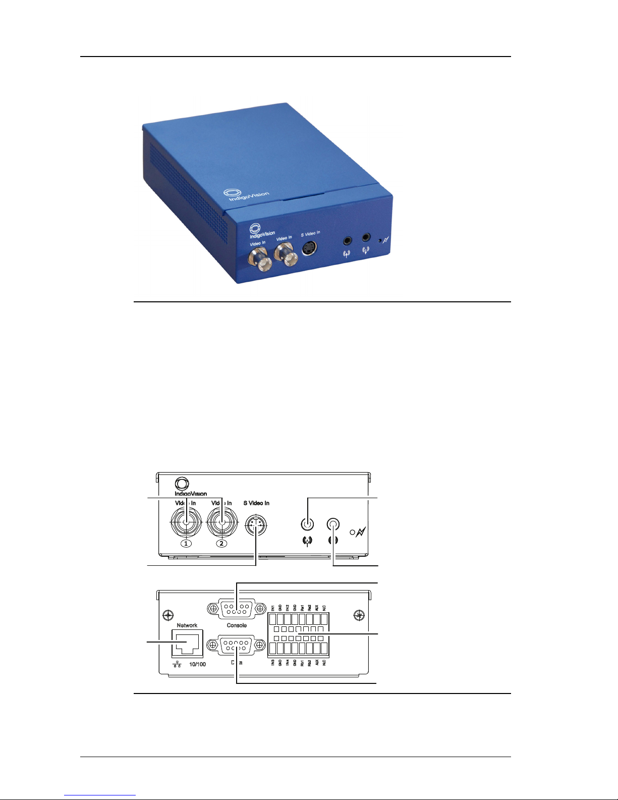
Figure 1: Dual Channel Encoder
Dimensions
• 169mm (l) x 123mm (w) x 44mm (d)
Weight
• 0.6Kg (excluding power supply)
Connections
There are connections on both the front and rear of the device.
1
2
3
4
5
7
8
6
Figure 2: Connections - fr ont and rear
1. 2x Composite Video In
2 Hardware Description Dual Channel Encoder - 9000 Range

User Guide - v8 9
2. S-Video In
3. Network
4. Audio In
5. Audio Out
6. Console Port
7. Terminal Block
8. Data Port
Composite video input
The video connectors of the device are standard 75 Ohm terminated BNC connectors. The
input format is composite video on these connectors.
Use input 1 for the primary channel and input 2 for the secondary channel.
When using the S-Video input, Composite Video input 1 is not available.
S-Video input
For sources which support S-Video, IndigoVision recommends that you use the S-Video input
to achieve high quality video at lower bitrates.
S-Video is only available on the primary channel.
Table 1: S- Video connector pin numbering
1 Y GND
2 C GND
3 Y (LUMA)
4 C (CHROMA)
When using the S-Video input, Composite Video input 1 is not available.
Audio In
The Audio In is a mono input, 3.5mm jack (stereo type) and supports an input signal
amplitude of up to 1V p-p. The audio input gain of the device can be adjusted from the audio
web page to cater for lower input signal amplitudes.
The audio input for the primary channel (channel 1) is delivered on the tip, and the audio input
for the secondary channel (channel 2) is delivered on the ring. The ground (GND) connection
for both channels is on the sleeve.
Audio Out
The Audio Out is a 3.5mm jack and provides an output signal amplitude of up to 1V p-p. This
output is not capable of driving a speaker directly. It should be connected to a suitable
Dual Channel Encoder - 9000 Range 2 Hardware Description

10 User Guide - v8
amplifier, powered speakers or headphones. The minimum load impedance rating of this
output is 16 Ohms.
The audio output for the primary channel (channel 1) is delivered on the tip, and the audio
output for the secondary channel (channel 2) is delivered on the ring. The ground (GND)
connection for both channels is on the sleeve.
Network
The network connector is an RJ45 connector. It is auto-sensing 10/100 Base-T Ethernet
• Maximum length: 100m
• CAT5 cables or higher
Console port
The Console port is a standard RS232 serial connection with a 9-pin DSub connector.
► For more information about configuring the device using this port, see "Using the serial
port connection" on page 20.
This port can also be used as a secondary data port.
► For more information, see "Using the serial port as an RS232 data port" on page 25
Table 2: Console port pin number ing
Pin RS232 Function
1 NC
2 Rx
3 Tx
4 NC
5 GND
6 NC
7 NC
8 NC
9 NC
Data port
The Data port is an RS485/422 port with a 9-pin DSub connector.
The device supports other RS485 devices in a point-to-point configuration only.
Table 3: Data port pin numbering
Pin RS485/422 Fu nction
1
2 Rx-
3 Tx-
2 Hardware Description Dual Channel Encoder - 9000 Range

User Guide - v8 11
Pin RS485/422 Fu nction
4
5 GND
6
7 Tx+
8 Rx+
9
Terminal block
The terminal block provides connector pins for the binary inputs and outputs, as well as the
power supply.
► For more information, see "Powering the device" on page 16
There are four binary inputs, and two binary outputs.
Name Descript ion
IN1-2 Binary Input 1-2 (Primary channel)
IN3-4 Binary Input 3-4 (Secondary channel)
RA1 RA2 Binary Output Relay 1 (Primary channel)
RB1 RB2 Binary Output Relay 2 (Secondary channel)
GND GND
AUX +24V AC/DC Auxiliary Power
NC Not Connected (Standar d)
HTR +24V AC/DC Heater Power (Extended Temp.)
Binary input
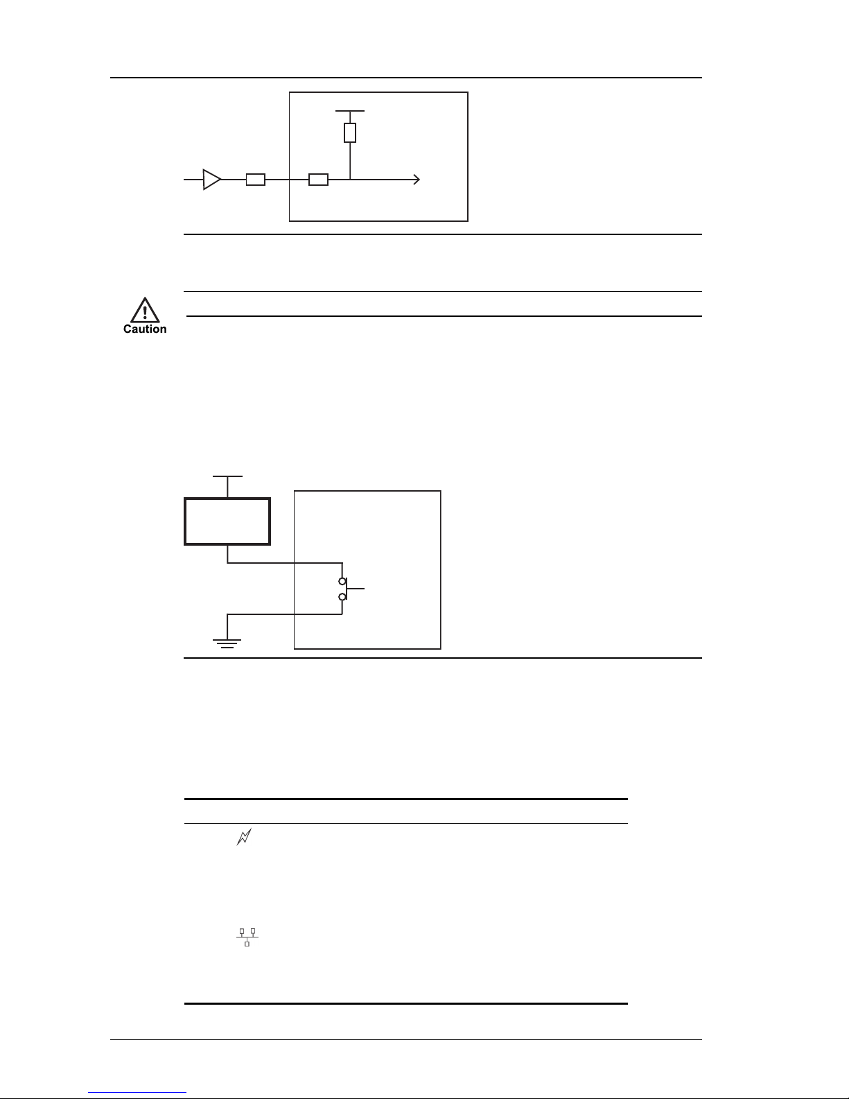
The binary inputs allow you to connect external trigger sources to the device. The pins
provide pull-up inputs that are normally in the high state. To change the state, ground the input
pin as shown in Figure 3: on page 11.
1.8V
Input
10K
470Ω
Protected to 24V
Figure 3: Example binary input - low state
For input voltages greater than 24V DC, an external resistor is required in series with the input
pin.
Dual Channel Encoder - 9000 Range 2 Hardware Description
12 User Guide - v8
1.8V
48V Input
10K
470Ω10K
Figure 4: Binary input for voltages gr eater than 24V DC
► For more information, see "Binary input" on page 46
Input voltages above 50Vpk at Vin will irrevocably damage the device.
Binary output
Binary output pins are controlled by your software applications. These pins are electronically
switched and are either open-circuit or closed.
When closed, the effective resistance between Rx 1 and Rx 2 is not greater than 4Ω.
External
device
Supply
Rx1
Rx2
Figure 5: Example binary output
► For more information, see "Binary output" on page 47
Indicator LEDs
When the device is powered up, the LEDs indicate the activity and status as described in on
page 12.
Name
Image Colo r Statu s Meanin g
Activity
Green Flashing Device is operating normally
Solid on/off System failure
10/100 10/100 Green On 100Base-TX mode
Off 10Base-T mode
Link Amber Flashing Link is up and there is network traffic
On Link is up, but there is no network traffic
Off Link is down
2 Hardware Description Dual Channel Encoder - 9000 Range

User Guide - v8 13
Power requirements
The Dual Channel Encoder can be powered by the following methods:
• Power over Ethernet (PoE): 802.3af
• Auxiliary power
• 24V DC (+10%/-30%)
• 24V AC
► For more information, see "Powering the device" on page 16
The Extended Temperature variant additionally has a 24V AC/DC input to power a heater.
Power supplies are orderable separately from IndigoVision.
Power consumption
• Standard Temperature variant: 6W max
• Extended Temperature variant: 6W max
• Heater: 30W max
Dual Channel Encoder - 9000 Range 2 Hardware Description

14 User Guide - v8
2 Hardware Description Dual Channel Encoder - 9000 Range
User Guide - v8 15
3 GETTING STARTED
This chapter describes the initial steps required to start using your Dual Channel Encoder.
Package contents
Before continuing, please check that you have been shipped the items listed for your device.
Dual Channel Encoder
4
2
3
5
1
6
7
8
Figure 6: Standard variant package contents
1. 2x Composite Video In
2. S-Video In
3. Audio In
4. Audio Out
5. Network
6. Console Port
 Loading...