

IndigoVision 9000 Range, 9000 Series User Manual

IndigoVision
Enhanced SDFixed Dome
9000 Range
User Guide

2 User Guide - v7
THIS MANUAL WAS CREATED ON 03 SEPTEMBER 2014.
DOCUMENT ID: IU-DOM-MAN001-7
Legal considerations
LAWS THAT CAN VARY FROM COUNTRY TO COUNTRY MAY PROHIBIT CAME RA SURVEILLANCE . P LE ASE ENSURE THAT THE RELEVA NT LAWS
ARE FULLY UNDERSTOOD FOR THE PA RTICULAR COUNTRY OR REGION IN WHICH YOU WILL BE O PERA TING THIS EQ UIPMENT. INDIGO VISION
LTD. A CCEPTS NO LIABILITY FOR IMPROP ER OR ILLEGAL USE OF THIS PRODUCT.
Copyright
COPYRIGHT © INDIGOVISION LIMITED. ALL RIGHTS RESE RVED.
THIS MANUAL IS PROTECTED B Y NATIONAL AND INTERNATIONAL COPY RIGHT AND OTHER LAWS . UNAUTHORIZED STORAGE, REPRODUCTION,
TRANSMISSION AND/OR DISTRIBUTION OF THIS MANUAL, OR ANY PART OF IT, MA Y RESULT IN CIVIL AND/OR CRIMINAL PROCEEDINGS.
INDIGOVISION IS A TRADEMARK OF INDIGOVISION LIMITED AND IS REGISTE RED IN CERTAIN COUNTRIES. SMS4, CAMERA G ATEWAY, AND
MOBILE CENTER ARE UNREGISTERED TRADEMARKS OF INDIGOVISION LIMITED. ALL OTHER P RODUCT NAMES REFERRED TO IN THIS MANUAL
ARE TRADEMARKS OF THEIR RESPECTIVE OWNERS.
SAVE AS O THERWISE A GREED WITH INDIGO VISION LIMITED AND /OR INDIGO VISION, I NC., THIS MANUAL IS PRO VIDED WITHOUT EX PRES S
REPRESENTATION AND/OR WARRANTY OF ANY KIND. T O THE FULLEST EXTENT PERMITTED BY A PPL ICABLE LA WS, I NDIGOV ISION LIMITED
AND INDIGO VISION , I NC. DISCLA IM ALL IMPLIED REPRES ENTATIONS , WARRANTIES, CONDITIONS AND/OR O BLIGA TIONS O F EV ERY KIND IN
RESPE CT OF THIS MANUAL. ACCORDINGLY , SAVE AS OTHERWISE AG REED WITH INDIGOVISION LIMITED AND/OR I NDIGOVISION , INC., THIS
MANUAL IS PROVIDED O N AN “A S IS”, “WITH ALL FAULTS” AND “A S AVAILABLE ” BA SIS. PLEASE CONTACT INDIGO VISION LIMITED (EITHER BY
POS T OR BY E- MAIL AT P ARTNER.SUPPO RT@INDIGOVISION.COM ) WITH A NY S UGGE STED CORRECTIONS AND/O R IMPROVEMENTS TO THIS
MANUAL.
SAVE AS OTHERWISE AGREE D WITH I NDIGOV ISION LIMITED AND/ OR INDIGO VISION, INC., THE LIABILITY OF INDIGO VISION LIMITED AND
INDIGOVISION, INC. FOR ANY LOSS (O THER THAN DEATH OR PERSO NAL INJURY) A RISING AS A RESULT OF ANY NEGLIGENT ACT OR OMISSION
BY I NDIGO V ISION L IMITED AND /OR INDIGO VISION, I NC . IN CONNECTION WITH THIS MA NUAL AND/OR AS A RES ULT OF ANY USE OF O R
RELIANCE ON THIS MANUAL IS EXCLUDED TO THE FULLEST EXTENT PERMITTED BY APPLICABLE LAWS .
Contact address
IndigoVision Limited
Charles Darwin House,
The Edinburgh Technopole,
Edinburgh,
EH26 0PY
Enhanced SDFixed Dome - 9000 Range

User Guide - v7 3
TABLE OF CONTENTS
Legal considerations 2
Copyright 2
Contact address 2
1 About This Guide 7
Safety notices 7
2 Hardware Description 9
Variants 9
Internal variant 9
Standard Vandal Resistant variant 10
Environmental Vandal Resistant variant 11
Connections 12
Binary IO connections 13
Power requirements 14
Cabling requirements 14
Wiring requirements 14
3 Getting Started 17
Package contents 17
Internal variant 17
Standard Vandal Resistant variant 18
Environmental Vandal Resistant variant 19
Powering up the 9000 SD Fixed Dome 20
Using a Power over Ethernet switch 20
Using a Power over Ethernet injector/midspan 20
Auxiliary power 20
Initial camera configuration 21
Initial IP properties 21
Using the configuration pages 21
Using the console port 24
Attaching the device to the network 26
4 Installation 27
Installing the Internal variant 27
Fit the Mounting Plate 27
Run the cabling to the Mounting Plate 28
Fit the Camera Assembly to the Mounting Plate 28
Setting up the sensor 29
Focus Procedure 30
Installing the Standard Vandal Resistant variant 30
Without Exit Collar 30

4 User Guide - v7
With Exit Collar 33
Installing the Environmental Vandal Resistant variant 37
Run the cabling to the access point 37
Fit the Exit Collar 37
Connect the heater power supply 38
Fit the camera to the Exit Collar 39
Setting up the sensor 39
Focus Procedure 40
5 Operations 41
Using a 9-22mm lens 41
Low temperature start-up 41
Heater and fan operation 42
6 Configuration 43
Web Configuration pages 43
Home 43
Network 43
Date & Time 44
Video 45
Profiles 46
Encoder 47
Analytics 48
Audio 51
Binary Input/Output 51
Events 52
Advanced Network Configuration 52
Network Security 53
Firmware Upgrade 55
Diagnostics 55
Enabling and disabling web configuration 56
7 Hardware Specification 57
Codec specification 57
Video 57
Video codec 57
Resolution 57
Audio codec 57
Sensor specification 57
Input/output 58
Console 58
Console serial port 58
Analog video output 58
Network connections 59
Environment 59
Regulatory and approvals 59
A Optional Mount Components 61
In-Ceiling flush mount 61
Bracket Wall mount 62
Enhanced SDFixed Dome - 9000 Range

User Guide - v7 5
Wall mount 63
Swan-Neck mount 64
Vertical mount 65
NPT adapters 66
Corner Mount adapter 67
Pole Mount adapter 68
Enhanced SDFixed Dome - 9000 Range

6 User Guide - v7
Enhanced SDFixed Dome - 9000 Range
User Guide - v7 7
1 ABOUT THIS GUIDE
This guide is written for users of the IndigoVision 9000 SD Fixed Dome. It provides
installation and configuration information for the device variants, as well as a description of
the hardware and specifications.
Please ensure you read the instructions provided in the guide before using the device.
Safety notices
This guide uses the following formats for safety notices:
Indicates a hazardous situation which, if not avoided, could result in death or serious injury.
Indicates a hazardous situation which, if not avoided, could result in moderate injury, damage
the product, or lead to loss of data.
Indicates a hazardous situation which, if not avoided, may seriously impair operations.
Additional information relating to the current section.

8 User Guide - v7
1 About This Guide Enhanced SDFixed Dome - 9000 Range
User Guide - v7 9
2 HARDWARE DESCRIPTION
This chapter details the 9000 SD Fixed Dome, its connections, and its weights and
dimensions.
Variants
The IndigoVision 9000 SD Fixed Dome is available in the following variants:
• Internal Dome
The Internal Dome is a plastic encased dome camera for internal wall or ceiling mount.
• Standard Vandal Resistant Dome
The Standard Vandal Resistant Dome is a metal encased vandal-resistant dome
camera for internal wall or ceiling mount.
• Environmental Vandal Resistant Dome
The Environmental Vandal Resistant Dome is a metal encased vandal-resistant dome
camera for external wall or ceiling mount.
All variants are H.264 units, and use a Day-Night color/monochrome sensor.
Ensure that you read the instructions within this document relating to the camera variant you
have been shipped.
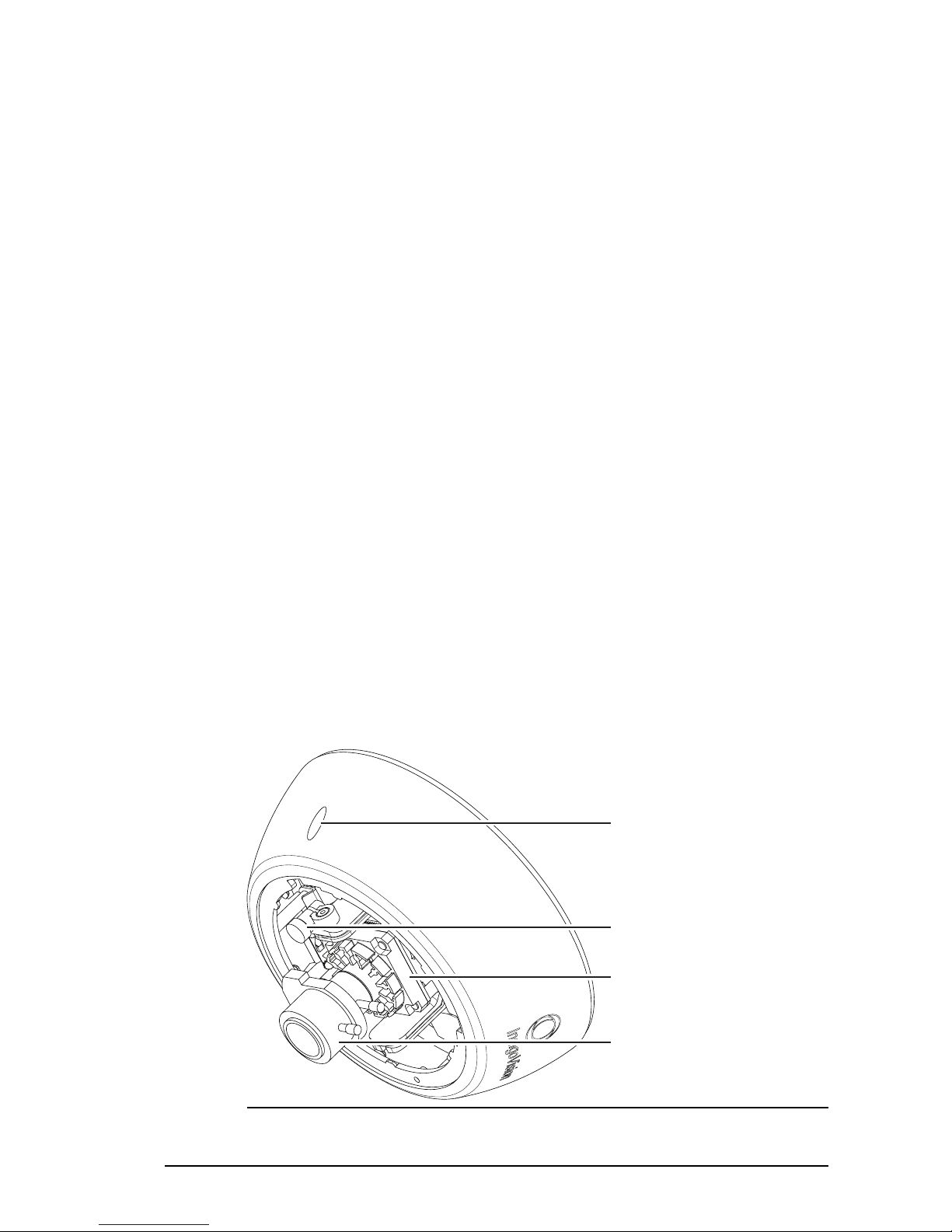
Internal variant
Security
Screw
Locking
Screw
Sensor
Assembly
Lens
Figure 1: Internal variant- front view
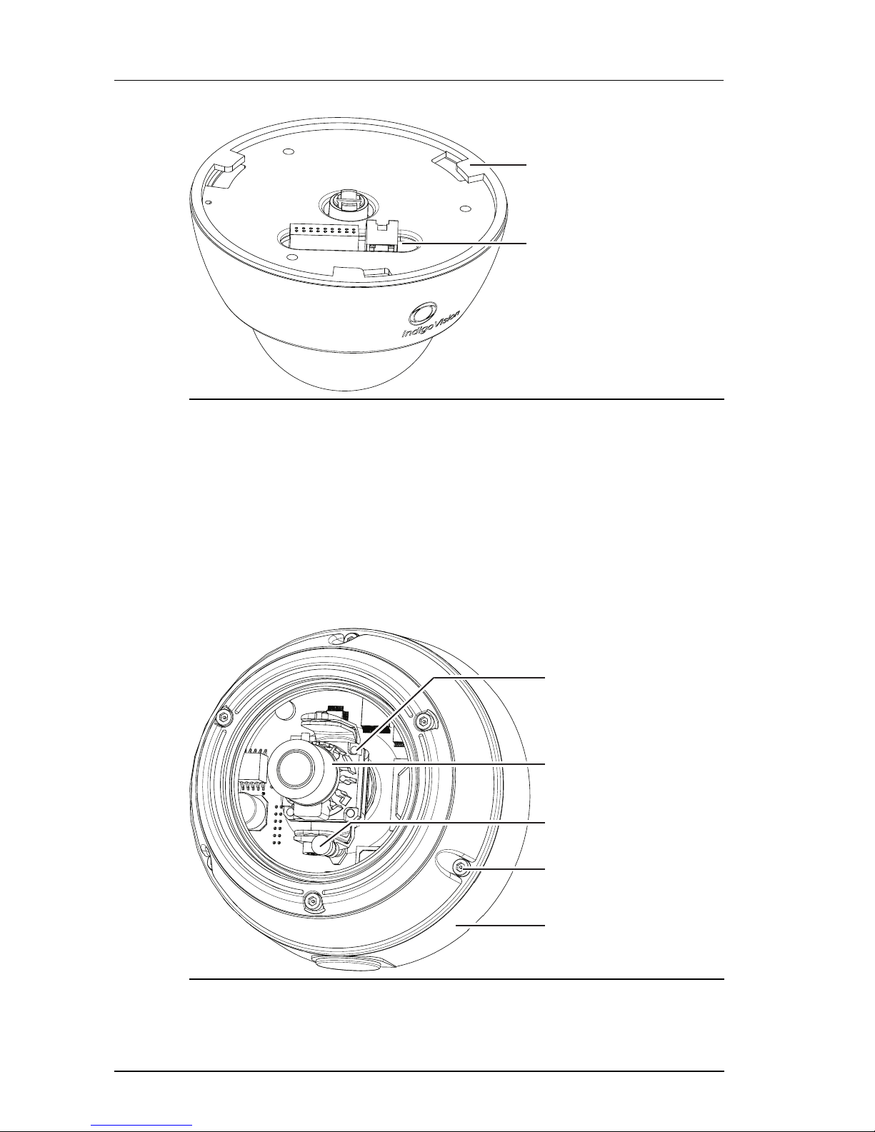
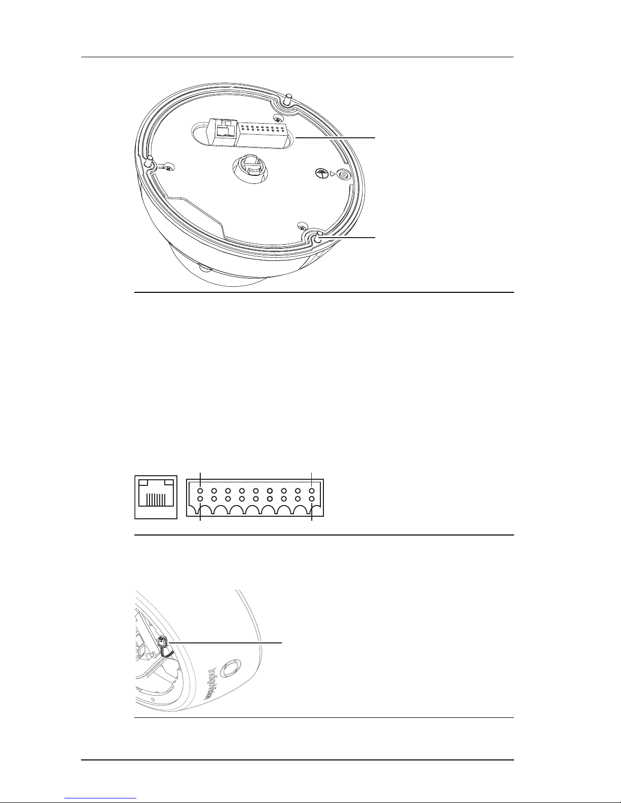
10 User Guide - v7
Bayonet Fixing
Point
Connection
Panel
Figure 2: Internal variant - rear view
Dimensions
• Internal Dome: 155mm (d) x 110mm (h)
Weight
• 0.7kg (including packaging)
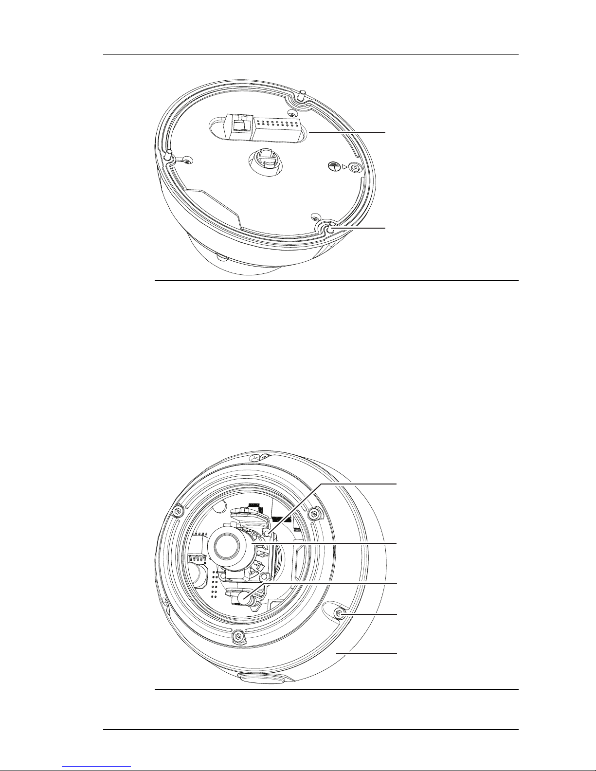
Standard Vandal Resistant variant
Camera
Lens
Assembly
Locking
Screw
Security
Screw
Lens
Exit Collar
Figure 3: Standard Vandal Resistant variant - fr ont view
2 Hardware Description Enhanced SDFixed Dome - 9000 Range
User Guide - v7 11
Connection
Panel
Security
Screw
Figure 4: Standard Vandal Resistant variant - r ear view (no exit collar)
Dimensions
• Without Exit Collar: 160mm (d) x 103mm (h)
• With Exit Collar: 163mm (d) x 131mm (h)
Weight
• 1.1kg (including packaging)
Environmental Vandal Resistant variant
Camera
Lens
Assembly
Locking
Screw
Security
Screw
Lens
Exit Collar
Figure 5: Environmental Vandal Resistant variant - front view
Enhanced SDFixed Dome - 9000 Range 2 Hardware Description
12 User Guide - v7
Connection
Panel
Security
Screw
Figure 6: Environmental Vandal Resistant variant - r ear view (no exit collar)
Dimensions
• 163mm (d) x 131mm (h)
Weight
• 1.3kg (including packaging)
Connections
The camera connections are situated on the back of the camera.
Pin 18
Pin 17
Pin 2
Pin 1
RJ45
Figure 7: Camera connections
An analog video cable with a 2-way connector is available to help during camera installation.
This connector is located on a flying lead connected to the camera's main circuit board.
2-way analog connector
Figure 8: 2-way analog connector
2 Hardware Description Enhanced SDFixed Dome - 9000 Range
User Guide - v7 13
After using the 2-way connector, ensure you tuck it under the cover to prevent it from
obscuring the field of view of the camera.
Binary IO connections
The camera has 2 opto-isolated binary inputs and 1 opto-isolated binary output. The table
below provides details of the binary IO connections on the 18-way IO connector.
Table 1: 18-way IO connector Binary IO connections
Signal Pin Number
IN1+ 5
IN1- 8
IN2+ 7
IN2- 10
OUT1A 4
OUT1B 6
The connector's pin numbering scheme is shown in Figure 7: on page 12.
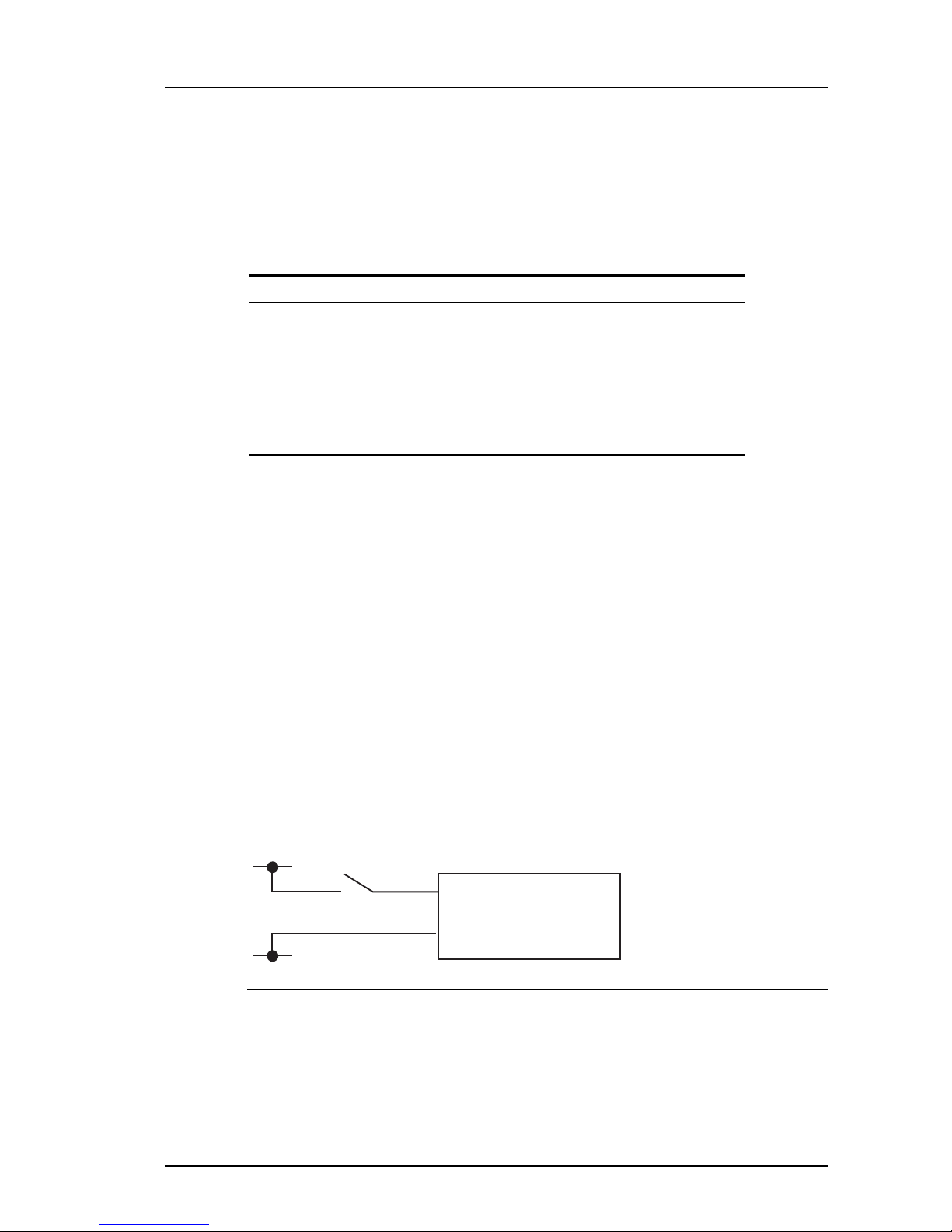
Binary input
• Two opto-isolated binary inputs
• Maximum Input voltage 24V DC
• To set a Binary Input High, VIN should be 4V DC minimum, 24V DC maximum
• To set a Binary Input Low, VIN should be 1V DC maximum
The binary inputs require an external voltage source to drive them. The voltage source is
normally connected via a controlled switch to a binary input. The positive connection from the
voltage source should be wired to the IN + pin (via switch), the negative connection to the IN pin.
When the camera is enabled via Control Center to generate binary IO events, connecting the
voltage source to an input triggers a rising edge binary IO event from the camera.
Disconnecting the voltage source from an input triggers a falling edge binary IO event from
the camera. The voltage source used should be between 4V and 24V DC. See Figure 9: on
page 13 for a simple example of a binary input connection.
Fixed IP
Dome Camera
IN+
IN-
+Vs
-Vs
Figure 9: Binary input connection
If voltage sources greater than 24V DC must be used then an external resistor is required.
The value of this resistor can be calculated as follows:
R = [ 100 * (VON - 1) - 1500 ] ohms rounded down to the nearest preferred resistor
value, where VON is the desired voltage for a logic high.
e.g. for VON = 48V DC
Enhanced SDFixed Dome - 9000 Range 2 Hardware Description

14 User Guide - v7
R = [ 100 *( 48 - 1 ) - 1500 ]
= 4700 - 1500 = 3200
~ 3K
Binary output
The binary output consists of solid state relay contacts. The camera’s binary output contacts
are normally open and can be set to open or closed using Control Center.
When closed, the maximum resistance between the contacts is 2 ohms.
The maximum current carrying capacity of the contacts is 500mA at 25°C. The maximum
current has a linear de-rating factor of 5mA/°C. Therefore at 45°C the maximum current is
400mA.
The maximum voltage to be switched is 50Vpk.
Power requirements
• Power consumption: maximum 6W
• 12Vdc heater assembly power consumption (Environmental Vandal Resistant Dome
only): Typical 20W, maximum 30W
• Power Over Ethernet is IEEE 802.3af compliant.
Cabling requirements
Table 2: Video and Ethernet cablerequirements
Video BNC 75 ohm coax
Ethernet CAT5 (or higher) 100m max
An analog video cable with a 2-way connector is provided with the camera to help during
camera installation, Figure 8: on page 12.
Wiring requirements
Table 3: IO connector wiring requirements
Pin Signal Recommended Wire Gauge
Pin 1 AUX PWR 18 AWG
Pin 2 AUX PWR 18 AWG
Pin 3 NOT USED N/A
Pin 4 OUT1A 22 AWG
Pin 5 IN1+ 22 AWG
Pin 6 OUT1B 22 AWG
Pin 7 IN2+ 22 AWG
Pin 8 IN1- 22 AWG
Pin 9 GND 22 AWG
2 Hardware Description Enhanced SDFixed Dome - 9000 Range

User Guide - v7 15
Pin Signal Recommended Wire Gauge
Pin 10 IN2- 22 AWG
Pin 11 CONSOLE RX 22 AWG
Pin 12 CONSOLE T X 22 AWG
Pin 13 GND (Audio Out Return) 22 AWG
Pin 14 LINE IN LEFT (Stereo) 22 AWG
Pin 15 PHONES OUT (Mono) 22 AWG
Pin 16 LINE IN RIGHT (Stereo) 22 AWG
Pin 17 GND (Audio In Return) 22 AWG
Pin 18 MIC IN 22 AWG
Enhanced SDFixed Dome - 9000 Range 2 Hardware Description

16 User Guide - v7
2 Hardware Description Enhanced SDFixed Dome - 9000 Range
User Guide - v7 17
3 GETTING STARTED
This chapter describes the initial steps required to start using your 9000 SD Fixed Dome.
Package contents
Before continuing, please check that you have been shipped the items listed for your device.
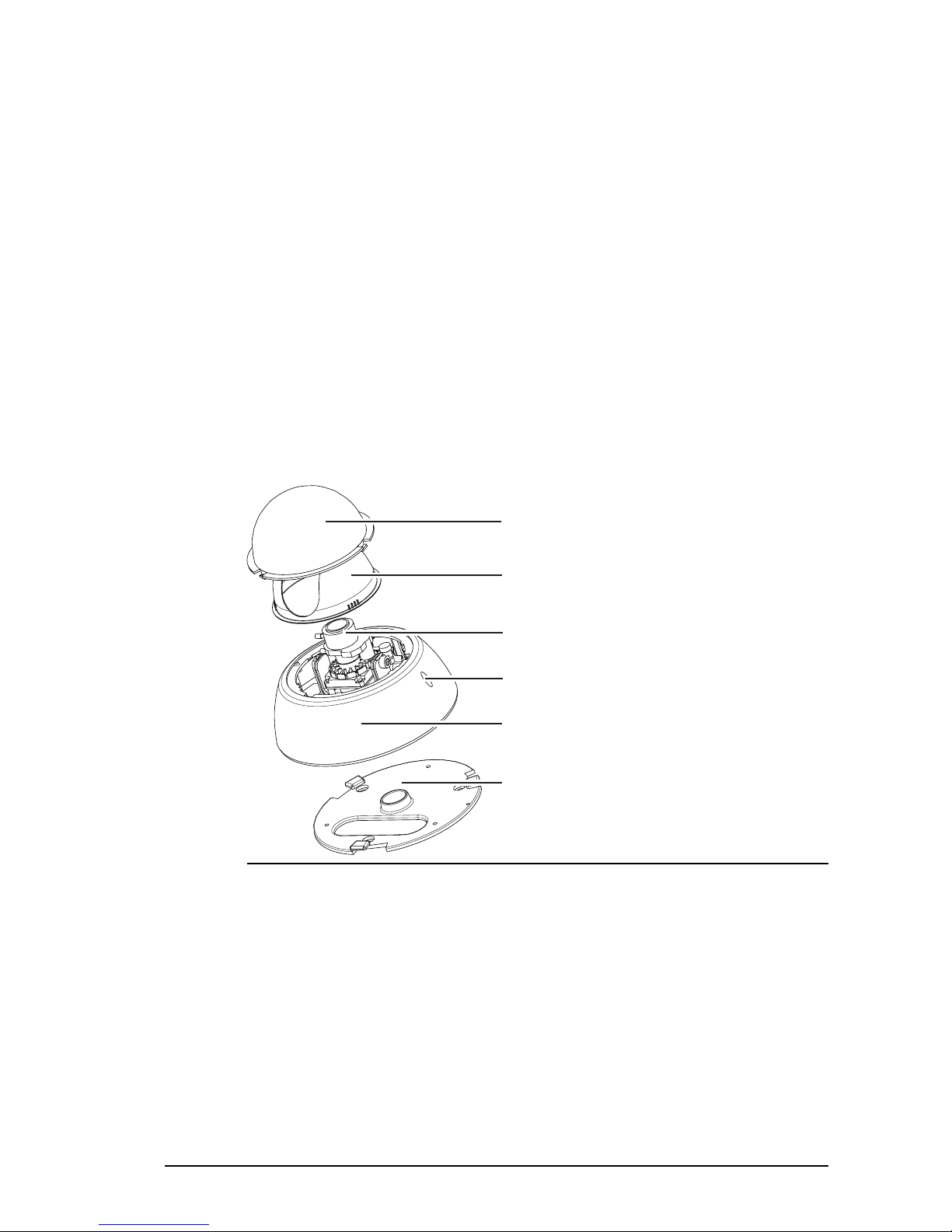
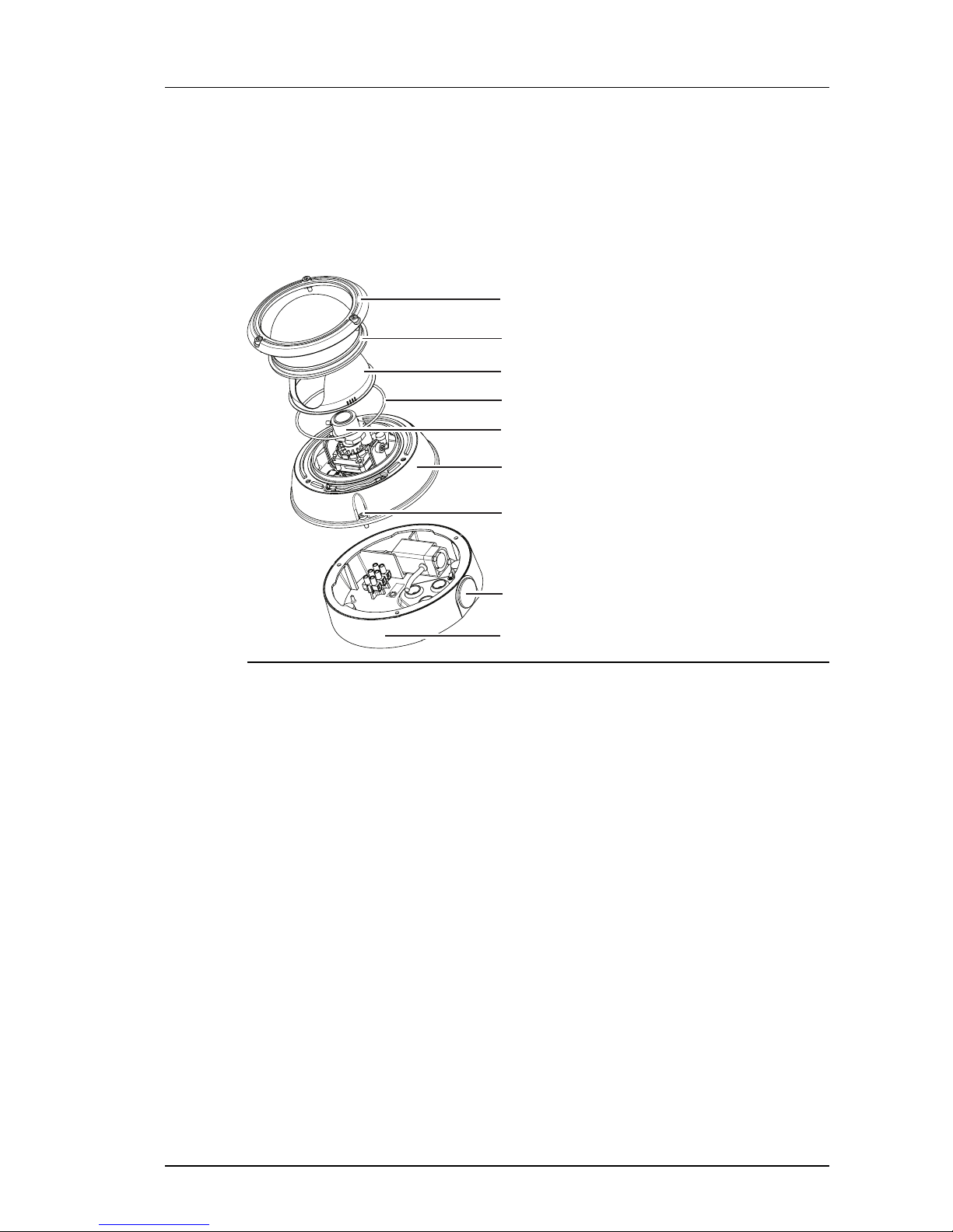
Internal variant
1.
4.
2.
3.
5.
6.
Figure 10: Internal variant package contents
1. Dome Bubble
2. Lens Shroud
3. Lens Assembly
4. Securing Screw
5. Camera Assembly
6. Mounting plate
In addition to the camera, the following items are also provided:
• 1 x analog video cable
• 2 x security screws
• 1 x allen key
18 User Guide - v7
Ensure you remove the packing material from inside the camera before operating the camera.
Remove the Dome Bubble from by rotating it anti-clockwise to its end stop position and lift it
off. The remove the lens shroud.
Ensure the cover fixing screw is not fitted before attempting to remove the dome bubble.
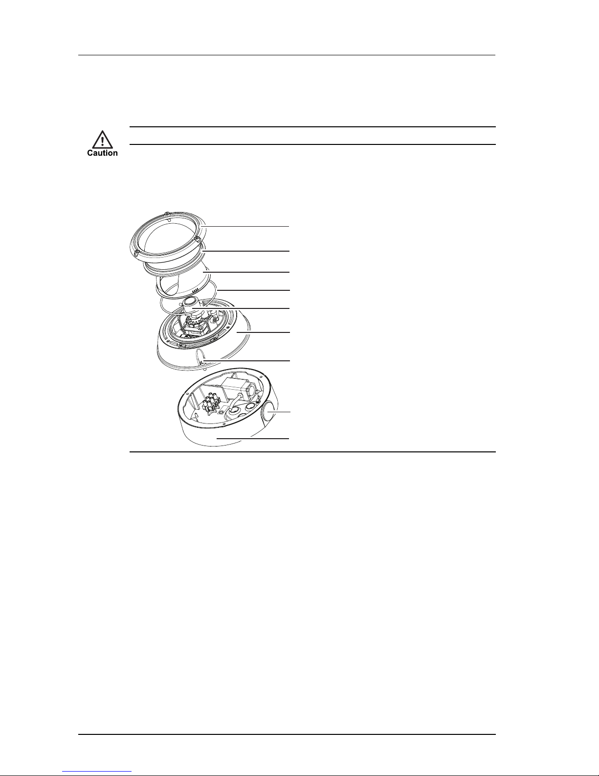
Standard Vandal Resistant variant
1.
4.
9.
3.
2.
5.
8.
6.
7.
Figure 11: Vandal Resistant variant package contents
1. Bezel
2. Dome Bubble
3. Lens Shroud
4. Seal
5. Lens Assembly
6. Camera Assembly
7. Security Screw (x3)
8. Exit Hole
9. Exit Collar with sealing plugs and gasket
In addition to the camera, the following items are also provided:
• 1 x analog video cable
• 1 x Ethernet cable with grommet
• 1 x allen key
• 1 x torx bit
• 1 x desiccant bag
• 1 x spare grommet
• 1 x mini inline-coupler for Ethernet
3 Getting Started Enhanced SDFixed Dome - 9000 Range
User Guide - v7 19
• 1 x hole template
Ensure you remove the packing material from inside the camera before operating the camera.
Remove the camera bezel by unscrewing the three security screws situated around the dome
bubble (use the Torx T10 bit supplied). Then lift off the bezel, the dome bubble, and the lens
shroud.
Environmental Vandal Resistant variant
1.
4.
9.
3.
2.
5.
8.
6.
7.
Figure 12: Vandal Resistant variant package contents
1. Bezel
2. Dome Bubble
3. Lens Shroud
4. Seal
5. Lens Assembly
6. Camera Assembly
7. Security Screw (x3)
8. Exit Hole
9. Exit Collar with sealing plugs and gasket
In addition to the camera, the following items are also provided:
• 1 x analog video cable
• 1 x Ethernet cable with grommet
• 1 x allen key
• 1 x torx bit
• 1 x 12Vdc power supply (for heater)
• 1 x desiccant bag
• 1 x spare grommet
• 1 x mini inline-coupler for Ethernet
• 1 x hole template
Enhanced SDFixed Dome - 9000 Range 3 Getting Started
20 User Guide - v7
Ensure you remove the packing material from inside the camera before operating the camera.
First remove the camera bezel by unscrewing the three security screws situated around the
dome bubble (use the Torx T10 bit supplied). Lift off the bezel, the dome bubble, and the lens
shroud.
Powering up the 9000 SD Fixed Dome
The camera is a Power Over Ethernet (PoE) powered device compliant with the IEEE802.3af
standard.
There are a number of methods of powering up the camera:
• Power over Ethernet (PoE) switch
• PoE injector/midspan
• Auxiliary power
The camera dissipates 6W maximum power, excluding the heater power.
When operating in temperatures below 0°C (32°F), the Environmental Vandal Resistant
variant requires a 12V DC auxiliary power supply to operate the heaters.
Using a Power over Ethernet switch
To power up the camera using a Power over Ethernet (PoE) compliant switch, attach the
CAT5 cable for the camera to a PoE switch.
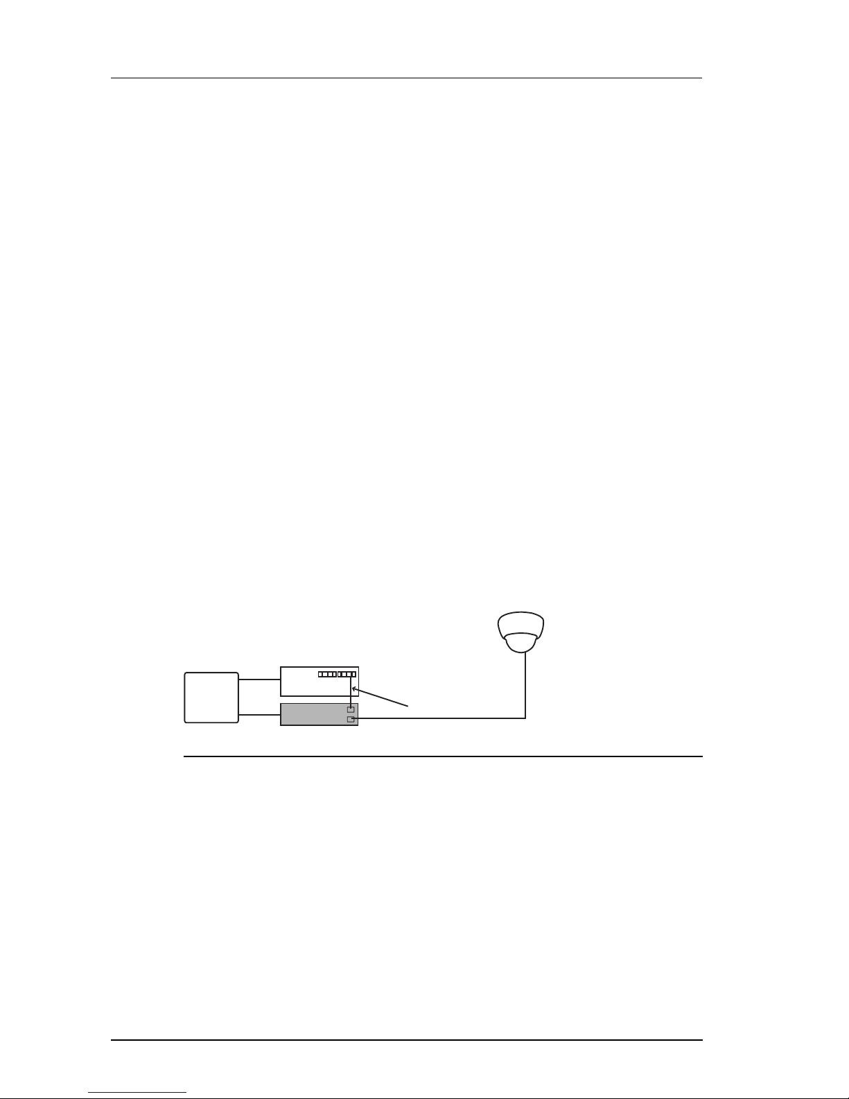
Using a Power over Ethernet injector/midspan
If a Power over Ethernet (PoE) switch is not available, the camera can be powered using a
PoE injector/midspan, such as Phihong POE36U-1AT.
Fixed
Dome
Cat5 cable
Network switch
PoE Midspan
Mains
Power
In
Out
Figure 13: Using a PoE injector/midspan
Auxiliary power
The camera can be powered using the auxiliary power input on pins 1 and 2 of the 18-way I/O
connector on the rear of the camera.
► See "Connections" on page 12 for details about the pin numbering scheme of the I/O
connector.
Auxiliary power requirements are 24V AC or 24V DC at 250mA (6VA max).
Use 18AWG (or 1mm2) cable to connect an auxiliary power supply to the camera.
The auxiliary power input to the camera is not polarity sensitive, therefore, a DC power
supply can be connected in either polarity.
3 Getting Started Enhanced SDFixed Dome - 9000 Range
User Guide - v7 21
When using an exit collar, use a 5-10mm diameter cable with a round section.
A 24V DC, 500mA PSU with mains power lead can be ordered from IndigoVision, the base
order code is 110004. Add -1 to the base order code for a UK IEC mains lead, -2 for a US IEC
mains lead and -3 for an EU IEC mains lead.
Initial camera configuration
You must configure your camera’s IP settings before you mount it in its final position.
You can configure your camera using the Web Configuration pages or the console port.
Initial IP properties
The following table displays the initial, default IP properties for a device.
Table 4: InitialIP properties
Initial Configuration
IP Address 10.5.1.10
Subnet Mask 255.0.0.0
Default Gateway 10.0.0.1
Using the configuration pages
To configure your device using the Configuration pages you must do the following:
1. Prepare an isolated network.
2. Prepare your PC for initial device configuration.
3. Configure your device. This includes specifying its IP address and subnet mask.
You must also have one of the following:
• A CAT5 crossover cable suitable for connection between the PC and the RJ45
connector on the device
• A power source
• 24V PSU
• PoE switch with two standard CAT5 cables
• PoE injector/midspan with one standard CAT5 cable and one CAT5 crossover
cable
Preparing an isolated network
Connect your device and the PC you are using to configure it on their own isolated network.
To do this, connect the device to the PC using an Ethernet cross-over cable.
Enhanced SDFixed Dome - 9000 Range 3 Getting Started
 Loading...