

IndigoVision 8000, 9000 Hardware Manual

8000/9000 Fixed IP Camera
Hardware Guide

THIS MANUAL WAS CREATED ON JUNE 20, 2008.
LEGAL CONSIDERATIONS
LAWS THAT CAN VARY FROM COUNTRY TO COUNTRY MAY PROHIBIT CAMERA SURVEILLANCE. PLEASE ENSURE THAT
THE RELEVANT LAWS ARE FULLY UNDERSTOOD FOR THE PARTICULAR COUNTRY OR REGION IN WHICH YOU WILL BE
OPERATING THIS EQUIPMENT. INDIGOVISION LTD. ACCEPTS NO LIABILITY FOR IMPROPER OR ILLEGAL USE OF THIS
PRODUCT.
COPYRIGHT
COPYRIGHT © 2008 INDIGOVISION LIMITED. ALL RIGHTS RESERVED.
T
HIS MANUAL IS PROTECTED BY NATIONAL AND INTERNATIONAL COPYRIGHT AND OTHER LAWS. UNAUTHORIZED
STORAGE, REPRODUCTION, TRANSMISSION AND/OR DISTRIBUTION OF THIS MANUAL, OR ANY PART OF IT, MAY RESULT
IN CIVIL AND/OR CRIMINAL PROCEEDINGS.
I
NDIGOVISION AND VIDEOBRIDGE ARE TRADEMARKS OF INDIGOVISION LIMITED AND ARE REGISTERED IN CERTAIN
COUNTRIES. ALL OTHER PRODUCT NAMES REFERRED TO IN THIS MANUAL ARE TRADEMARKS OF THEIR RESPECTIVE
OWNERS.
S
AVE AS OTHERWISE AGREED WITH INDIGOVISION LIMITED AND/OR INDIGOVISION, INC., THIS MANUAL IS PROVIDED
WITHOUT EXPRESS REPRESENTATION AND/OR WARRANTY OF ANY KIND. TO THE FULLEST EXTENT PERMITTED BY
APPLICABLE LAWS, INDIGOVISION LIMITED AND INDIGOVISION, INC. DISCLAIM ALL IMPLIED REPRESENTATIONS,
WARRANTIES, CONDITIONS AND/OR OBLIGATIONS OF EVERY KIND IN RESPECT OF THIS MANUAL. ACCORDINGLY, SAVE
AS OTHERWISE AGREED WITH INDIGOVISION LIMITED AND/OR INDIGOVISION, INC., THIS MANUAL IS PROVIDED ON AN
“
AS IS”, “WITH ALL FAULTS” AND “AS AVAILABLE” BASIS. PLEASE CONTACT INDIGOVISION LIMITED (EITHER BY POST OR
BY E-MAIL AT PARTNER.SUPPORT@INDIGOVISION.COM) WITH ANY SUGGESTED CORRECTIONS AND/OR IMPROVEMENTS
TO THIS MANUAL.
S
AVE AS OTHERWISE AGREED WITH INDIGOVISION LIMITED AND/OR INDIGOVISION, INC., THE LIABILITY OF
I
NDIGOVISION LIMITED AND INDIGOVISION, INC. FOR ANY LOSS (OTHER THAN DEATH OR PERSONAL INJURY) ARISING
AS A RESULT OF ANY NEGLIGENT ACT OR OMISSION BY INDIGOVISION LIMITED AND/OR INDIGOVISION, INC. IN
CONNECTION WITH THIS MANUAL AND/OR AS A RESULT OF ANY USE OF OR RELIANCE ON THIS MANUAL IS EXCLUDED
TO THE FULLEST EXTENT PERMITTED BY APPLICABLE LAWS.

TABLE OF CONTENTS
ABOUT THIS GUIDE..........................................5
Safety Notices ...............................................................5
1 GETTING STARTED........................................7
Camera Variants .................................................. .........7
Cabling Requirements ...................................................7
Wiring Requirements .....................................................8
Lens Requirements .......................................................8
Powering Up the Fixed IP Camera ................................9
Using a Power over Ethernet (PoE) switch.................9
Using a PoE Injector....................................................9
Using a PoE Midspan ..................................................9
Using Auxiliary Power .................................................10
Power Up LEDs.................................... ... ....................11
....................................................................................11
3
2 INITIAL FIXED IP CAMERA CONFIGURATION ....13
Initial IP Properties ........................................................13
Using the Web Configuration Pages .............................13
Step 1 — Preparing an Isolated Network....................14
Step 2 — Preparing for Initial Device Configuration....15
Step 3 — Configuring your Fixed IP Camera..............17
Using the Serial Port Connection ..................................20
Attaching the Fixed IP Camera to the Network .............23
3 FIXED IP CAMERA INSTALLATION ...................25
Mounting Instructions ....................................................25
Setting up a Day-Only Sensor .......................................25
Brightness Settings ......................... ... .........................26
Focus Adjustment........................................................26
Setting up a Day-Night Sensor ......................................28

4
Brightness Settings..................................................... 29
Focus Adjustment...................................... ... .............. 29
Day-Night Focus................................................. ........ 31
APPENDIX A – HARDWARE SPECIFICATION.......33
Codec Specification ......................................................33
Video ..........................................................................33
Audio .......................................................................... 33
Console Input/Output..................................................34
Analog Video Output .................................................. 34
Audio Mic Input........................................................... 34
Audio Line Input/Output..............................................34
Console Serial Port.....................................................35
Power Over Ethernet.................................................. 35
Network Connections ................................................. 35
Metrics........................................................................ 35
Environment ...............................................................36
Regulatory.................................................................. 36
Binary IO Connections .................................................. 36
Binary Input ................................................................37
Binary Output.............................................................. 38
Sensor Specification .....................................................39
INDEX ..........................................................41

ABOUT THIS GUIDE
This guide is written for users of IndigoVision ’ s Fixed IP Camera.
The camera is available as a Day-Only color camera, or a
Day-Night color/monochrome camera.
The camera is available as an 8000 (MPEG-4) or 9000 (H.264)
unit, and with or without audio.
This guide provides installation and configuration information
about the product, and a description of the hardware and
specifications.
For information on how to use the Web Configuration pages to
configure the unit, see the IndigoVision 8000/9000 Web
Configuration Guide.
Safety Notices
This guide uses the following formats for safety no ti ce s:
5
Note: Additional information relating to the current section.
Caution: Potential hazard that could seriously impair operation.

6
This page intentionally left blank

7
1
GETTING STARTED
Camera Variants
The IndigoVision Fixed Camera is available as a Day-Only
camera with a color sensor, or as a Day-Night with a
color/monochrome sensor.
The camera is available as an 8000 (MPEG-4) or 9000 (H.264)
unit, and with or without audio.
Before you begin, please check that you have been shipped the
following items for the Fixed IP Camera:
• 1 x Fixed IP Camera with blanking plug
• 1 x Fixed IP Camera Serial Cable
• 1 x CS mount lens
Cabling Requirements
This section details the cabling and wiring requirements for the
Fixed IP Camera.
Table 1 Ethernet Cable Requirements
Type
Ethernet CAT5 (or higher) 100m max

8
Wiring Requirements
Table 2 IO connector wiring requirements
Pin Signal
Pin 1 AUX PWR 18 AWG
Pin 2 AUX PWR 18 AWG
Pin 3 NOT USED N/A
Pin 4 OUT1A 22 AWG
Pin 5 IN1+ 22 AWG
Pin 6 OUT1B 22 AWG
Pin 7 IN2+ 22 AWG
Pin 8 IN1- 22 AWG
Pin 9 GND 22 AWG
Pin 10 IN2- 22 AWG
Pin 11 CONSOLE RX 22 AWG
Pin 12 CONSOLE TX 22 AWG
Pin 13 GND
Pin 14 VIDEO_OUT 75 ohm coax
Pin 15 AUDIO_OUT
Pin 16 AUDIO_LINE_IN
Pin 17 GND
Pin 18 AUDIO_MIC_IN
Recommended
Wire Gauge
Lens Requirements
The camera is supplied with a CS mount varifocal lens.
Other CS mount lenses can be used. The camera supports DC
direct drive auto-iris lenses via a standard 4-pin EIAJ connector
on the camera back panel.

Powering Up the Fixed IP Camera
The camera is a Power Over Ethernet (PoE) powered device
compliant with the IEEE802.3af standard. The 8000 camera
variants dissipate 7W maximum power, with the 9000 variants
dissipating 8W maximum.
There are four methods of powering up the camera:
• Using a Power over Ethernet (PoE) switch
• Using a PoE Injector
• Using a PoE Midspan
• Using Auxiliary Power (24v AC/DC)
These methods are detailed below.
Using a Power over Ethernet (PoE) switch
To power up the camera using a PoE-compliant switch, attach a
CAT5 cable between the camera and the PoE switch.
Using a PoE Injector
If a PoE switch is not available, the camera can be powered
using a PoE injector, such as Phihong PSA1GU-480.
9
Network switch
Figure 1 Using a PoE Injector
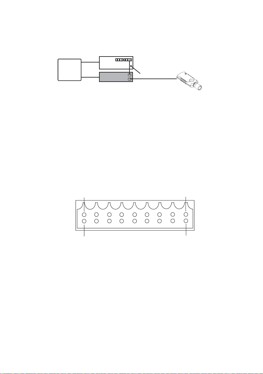
Using a PoE Midspan
If a PoE switch is not available, the camera can be powered
using a PoE Midspan.
Cat5 cable Cat5 cable
Fixed IP Camera
PoE Injector
Mains PowerMains Power
10
Network switch
Mains
Power
In
Out
PoE Midspan
Figure 2 Using a PoE Midspan
Using Auxiliary Power
If power from a PoE Ethernet switch, PoE Injector or PoE
Midspan is not available, the camera can be powered using the
auxiliary power input on pins 1 and 2 of the 18-way I/O connector
on the rear of the camera.
Auxiliary power requirements are 24V AC or 24V DC at 290mA
max (7VA max power) for 8000 camera variants, and 334mA
max (8VA max power) for 9000 camera variant. Figure 3 shows
the pin numbering scheme of the I/O connector.
Pin 1
Pin 2
Fixed IP Camera
Cat5 cable
Pin 17
Pin 18
Figure 3 I/O connector pin numbering scheme
Use 18AWG (or 1mm2) figure of eight (or twisted pair) cable to
connect an auxiliary power supply to the camera.
The auxiliary power input to the camera is not polarity sensitive;
therefore a DC power supply can be connected in either polarity.
A 24V DC, 500mA PSU with mains power lead can be ordered
from IndigoVision, the base order code is 110004. Add -1 to the
base order code for a UK IEC mains lead, -2 for a US IEC mains
lead and -3 for an EU IEC mains lead.

Power Up LEDs
When the camera is powered up, the LEDs indicate the following:
LED Color State Meaning
Power up Green Flashing Camera is powered up
Network/link Yellow Unlit Link is down
Solid Link is up, but there is no
network traffic
Flashing Link is up and there is
network traffic
11

12
This page intentionally left blank

13
2
INITIAL FIXED IP CAMERA
C
ONFIGURATION
You can configure your Fixed IP Camera using the Web
Configuration pages, or a serial connection. The Web
Configuration method is detailed below. If you are usi ng a serial
connection, see “Using the Serial Port Connection” on page 20.
Initial IP Properties
By default, these cameras are programmed with the IP properties
shown in Table 3.
Table 3 Default IP Properties
Initial Configuration
IP Address 10.5.1.10
Subnet Mask 255.0.0.0
Default Gateway 10.0.0.1
Using the Web Configuration Pages
To configure your camera using the Web Configuration pages
you must:
1 Prepare an isolated network.
2 Prepare your PC for initial device configuration.
3 Configure your camera. This includes specifying its IP
address and subnet mask.
14
You must also have one of the following:
• A CAT5 crossover cable suitable for connection between the
PC and the RJ45 connector on the camera, plus a 24V AC or
DC PSU, OR
• A PoE switch with two standard CAT5 cables, OR
• A PoE injector with one standard CAT5 cable and one CAT5
crossover cable.
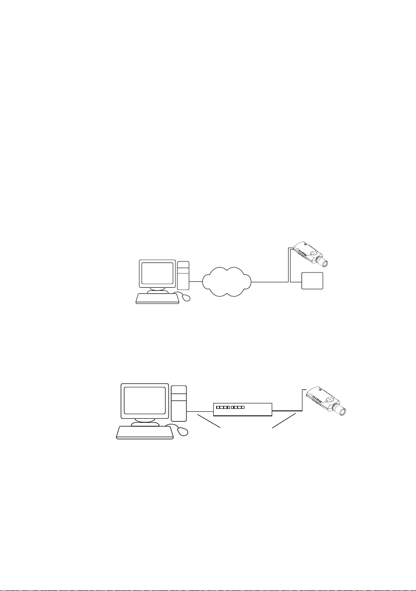
Step 1 — Preparing an Isolated Network
You should connect your camera and the PC you are using to
configure it on their own isolated network. To do this, connect the
unit to the PC using an Ethernet cross-over cable (see Figure 4.)
Fixed IP Camera
PC
Network
Power Supply
(not required
for PoE)
Figure 4 Connecting the unit and PC using a cross-over cable
Alternatively, you can connect the unit and PC to the same PoE
switch (Figure 5):
Fixed IP Camera
PC
PoE switch
Cat5 cable
Figure 5 Connecting the unit using a PoE switch

A further alternative is to connect the unit to the PC via a PoE
Injector (Figure 6):
Fixed IP Camera
15
PC
PoE injector
IN OUT
Cat5 cable
Cat5 crossover
cable
Mains
Power
Supply
Figure 6 Connecting the unit using a PoE injector
Step 2 — Preparing for Initial Device Configuration
All cameras are supplied with their IP address and subnet mask
set to 10.5.1.10 and 255.0.0.0 respectively. You cannot connect
the cameras to your network until you have changed these
settings to suit your network.
To change the factory defaults of your camera, you must first
(temporarily) modify your PC’s network settings.
Caution: Please note the original value of all settings that are to
be changed so that you can re-enter them when you
have completed the initial camera configuration.
To change your PC’s settings:
1 Use the Windows XP Network Settings configuration
application to set the PC’s IP address and subnet mask, as
follows:
a. In Windows Explorer, right-click Network Neighborhood
and select Properties.
b. Right-click Local Area Network and select Properties.
 Loading...