

IndigoVision 10-Channel Rack Hardware Manual

IndigoVision
10-Channel Rack
Hardware Guide

THIS MANUAL WAS CREATED ON 11 MAY 2011.
DOCUMENT ID: IU-RACK-MAN004-1
Legal Considerations
LAWS THAT CAN VARY F ROM COUNTRY TO COUNTRY MAY PROHIBIT CAMERA SURVEILLANCE. PLEASE ENSURE
THAT T HE RELEVANT LAWS ARE FULLY UNDERSTOOD FOR THE PARTICULAR COUNTRY OR REGION IN WHICH YOU
WILL BE OPERATING THIS EQUIPMENT. INDIGOVISION LTD. ACCEPTS NO LIABILITY FOR IMPROPER OR ILLEGAL
USE OF T HIS PRODUCT.
Copyright
COPYRIGHT © 2011 INDIGOVISION LIMITED. ALL RIGHTS RESERVED.
THIS MANUAL IS PROTECTED BY NATIONAL AND INTERNATIONAL COPYRIGHT AND OTHER LAWS. UNAUTHORIZED
STORAGE, REPRODUCTION, TRANSMISSION AND/OR DISTRIBUTION OF THIS MANUAL, OR ANY PART OF IT , MAY
RESULT IN CIVIL AND/OR CRIMINAL PROCEEDINGS.
INDIGOVISION IS A TRADEMARK OF INDIGOVISION LIMITED AND IS REGISTERED IN CERTAIN COUNTRIES. ALL
OTHER PRODUCT NAMES REFERRED T O IN THIS MANUAL ARE TRADEMARKS OF THEIR RESPECTIVE OWNERS.
SAVE AS OTHERWISE AGREED WITH INDIGOVISION LIMITED AND/OR INDIGOVISION, INC., T HIS MANUAL IS
PROVIDED WITHOUT EXPRESS REPRESENTAT ION AND/OR WARRANTY OF ANY KIND. TO THE FULLEST EXT ENT
PERMITTED BY APPLICABLE LAWS, INDIGOVISION LIMITED AND INDIGOVISION, INC. DISCLAIM ALL IMPLIED
REPRESENTATIONS, WARRANTIES, CONDITIONS AND/OR OBLIGATIONS OF EVERY KIND IN RESPECT OF T HIS
MANUAL. ACCORDINGLY, SAVE AS OT HERWISE AGREED WITH INDIGOVISION LIMITED AND/OR INDIGOVISION,
INC., T HIS MANUAL IS PROVIDED ON AN “AS IS”, “WIT H ALL FAULTS” AND “AS AVAILABLE” BASIS. PLEASE
CONTACT INDIGOVISION LIMITED (EITHER BY POST OR BY E-MAIL AT PARTNER.SUPPORT@INDIGOVISION.COM)
WITH ANY SUGGESTED CORRECTIONS AND/OR IMPROVEMENTS TO THIS MANUAL.
SAVE AS OTHERWISE AGREED WITH INDIGOVISION LIMITED AND/OR INDIGOVISION, INC., T HE LIABILITY OF
INDIGOVISION LIMITED AND INDIGOVISION, INC. FOR ANY LOSS (OTHER T HAN DEATH OR PERSONAL INJURY)
ARISING AS A RESULT OF ANY NEGLIGENT ACT OR OMISSION BY INDIGOVISION LIMITED AND/OR INDIGOVISION,
INC. IN CONNECTION WIT H T HIS MANUAL AND/OR AS A RESULT OF ANY USE OF OR RELIANCE ON THIS MANUAL IS
EXCLUDED TO THE FULLEST EXT ENT PERMITTED BY APPLICABLE LAWS.

3
TABLE OF CONTENTS
Legal Considerations 2
Copyright 2
1 About This Guide 5
Safety Notices 5
2 Product Overview 7
10-Channel Rack Overview 7
Network Switch Card Overview 8
Transmitter Card Overview 8
Receiver Card Overview 9
3 Installation and Configuration 11
Before You Begin 11
IP Configuration 12
Step 1: Inserting the Network Switch Card 12
Step 2: Preparing PC for Initial Device Configuration 13
Step 3: Inserting and Configuring Transmitter and/or
Receiver Card(s) 14
Step 4: Attaching a Video Source and Connecting
Alarms and Audio 18
Step 5: Installing the Rack into a Cabinet 19
Resetting the Rack Card to Factory Defaults 20
4 Configuring Redundancy 21
Configuring of Network Redundancy 21
Power Supply Redundancy 22
Generate a PSU Failure Event in Control Center 23

4
5 Specifications 27
Connector Pinouts 27
BNC Connector 27
Console RS232 Serial Settings 27
RS232 PTZ & Alarm Control Connections 28
RS422 PTZ & Alarm Control Connections 28
Audio Connector 28
Mechanical 29
Power Consumption 30
Transmitter/Receiver Card Specifications 31
10-Channel Rack Approvals 32
A Wiring The Binary Input and Output 33
Binary Input 33
Binary I/O Voltages less than 24 volts 33
Binary I/O Input Voltages greater than 24 volts 34
Binary Output 35
B Interface Card LEDs 37
All VPxxx Card LEDs 37
Network Switch Card LEDs 38

5
1 ABOUT THIS GUIDE
This Hardware Guide is written for users of the 10-Channel Rack.
It details how to configure the cards installed in the 10- Channel
Rack, and install the 10-Channel Rack into a cabinet.
It also provides specification and LED details for the 10-Channel
Rack and interface cards.
Safety Notices
This guide uses the following formats for safety notices:
Warning
Indicates a hazardous situation which, if not avoided, could result in death
or serious injury.
Caution
Indicates a hazardous situation which, if not avoided, could result in
moderate injury, damage the product, or lead to lossof data.
Notice
Indicates a hazardous situation which, if not avoided, may seriously impair
operations.
Additionalinformation relating to the current section.

7
2 PRODUCT OVERVIEW
10-Channel Rack Overview
The 10-Channel Rack is comprised of the following components:
• Rack chassis (includes backplane, power supply unit,
serial adaptor cable and Administrator software)
• Network switch card
• Up to ten transmitter and/or receiver cards.
It is used to convert up to four analog video and/or audio signals
into digital format and place them on a network. It can also be
used to decode digital video/audio and output it to an analog
monitor and/or suitable audio device.
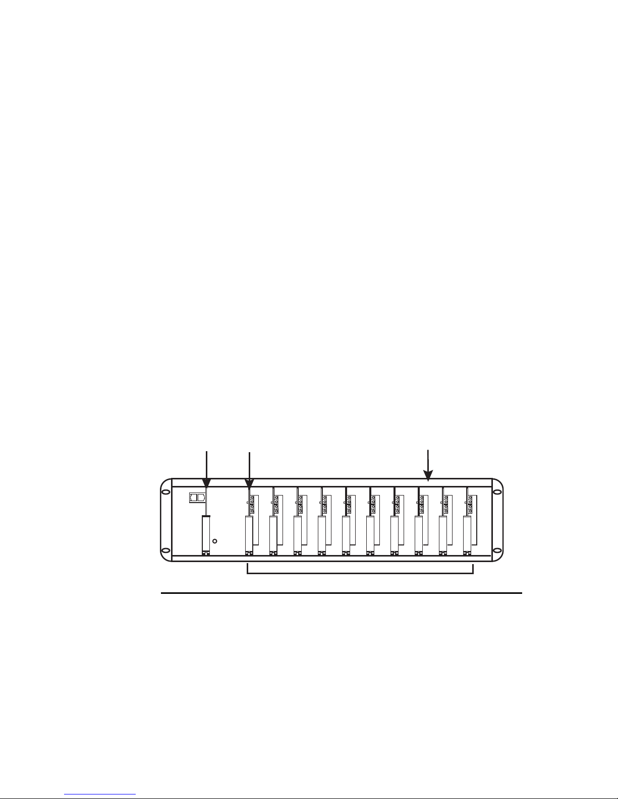
Network
Switch Card
Video cards
10-Channel Rack backplane
Video Card Serial
Configuration Slot 1
Figure 1 Fully populated 10-Channel Rack
The 10-Channel Rack allows up to ten analog cameras or analog
monitors to be connected and accessed by other products in the
IndigoVision range. These include Control Center and Networked
Video Recorders (NVR). This modular software can be added at
any stage during the system’s lifetime.

8
Network Switch Card Overview
The Network Switch card provides:
• Three 10/100/1000 Base-Tx uplink ports
• A dedicated 100Mbps Full-Duplex connection to each
individual Rack slot
This gives increased network bandwidth, network redundancy
(using two of the uplink ports), Gigabit Ethernet capability, and the
option of connecting directly to other IndigoVision products in a
local network (using the third uplink port).
Notice
The Ethernet link type of the Transmitter and/or Receiver cards must be
configured to Full-Duplex. Failure to do this will result in poor quality video
and audio.
Caution
The 10-Channel Rack must be powered down before the Network
Switch Card is inserted or removed.
Transmitter Card Overview
These cards, depending on the installed firmware, can digitize,
compress and transmit either a MPEG-4 (8000 Series cards) or
H.264 (9000 Series cards) video stream from a PAL/NTSC video
source to an IP network.
Audio data is full duplex, therefore analog audio can be input,
digitized, compressed and transmitted simultaneously with
another audio stream being received, decompressed, converted to
analog and output to a suitable device.
Alarm and RS232/422/485 serial data can be accessed via the
built-in terminal block connector.
You can configure these cards using a PC either with the Control
Center application, any Web browser, or using a serial cable and
a terminal emulator.

9
Transmitter Cards are hot swappable - they can be inserted or removed
while the 10-Channel Rack ispowered.
Receiver Card Overview
These cards can receive, decode and render an MPEG-4 or H.264
video stream from a corresponding Transmitter card.
The output analog signal is composite video (either PAL or NTSC
dependent on the format of the stream being received) which can
be output directly to a suitable analog monitor or VCR.
Audio data is full duplex, therefore analog audio can be input,
digitized, compressed and transmitted simultaneously with
another audio stream being received, decompressed, converted to
analog and output to a suitable device.
Alarm and RS232/422/485 serial data can be accessed via the
built-in terminal block connector.
You configure these cards using a PC either with the Control
Center application, any Web browser, or using a serial cable and
a terminal emulator.
Receiver Cards are hot swappable - they can be inserted or removed
while the 10-Channel Rack ispowered.


11
3 INSTALLATION AND
CONFIGURATION
This chapter contains the following information:
• "Before You Begin" on page 11
• "IP Configuration" on page 12
• "Resetting the Rack Card to Factory Defaults" on page 20
Before You Begin
Before you start installing the 10-Channel Rack, please ensure
that you have the following:
• A 10-Channel Rack backplane
• A network switch card
• At least one transmitter or receiver card
• A PC with a web browser for configuring the card(s)
• A power supply unit for the 10-Channel Rack
• A 19” cabinet and four screws to attach the 10-Channel
Rackto the cabinet
Warning
The power supply connector for the 10-Channel Rack is of the same type
as that for the IndigoVision NVR, however the voltages are different.
Using the wrong power supply to power either the Rack or NVR may
result in damage to the unit and or power supply. Always ensure the
correct power supply isused with the correct device.
The PSU connector for the NVR has a locking screw mechanism,
whereas the PSU for the Rackdoes not.
12
IP Configuration
This section takes you through the steps required to start using the
10-Channel Rack.
You must complete the following steps, which are explained in
more detail below.
1. Inserting the network switch card into the 10-Channel Rack.
2. Preparing your PC for initial device configuration (if required).
3. Reconfiguring each transmitter or receiver card from the
default to suit your network.
4. Attaching a video source and connecting alarms and audio (if
required).
5. Installing the 10-Channel Rack into a 19” cabinet (if required).
Step 1: Inserting the Network Switch Card
The network switch card is an integral part of the Rack.
You can have up to ten video cards in the Rack, but there is only
ever one network switch card.
1. Remove the front cover by loosening the thumb screws.
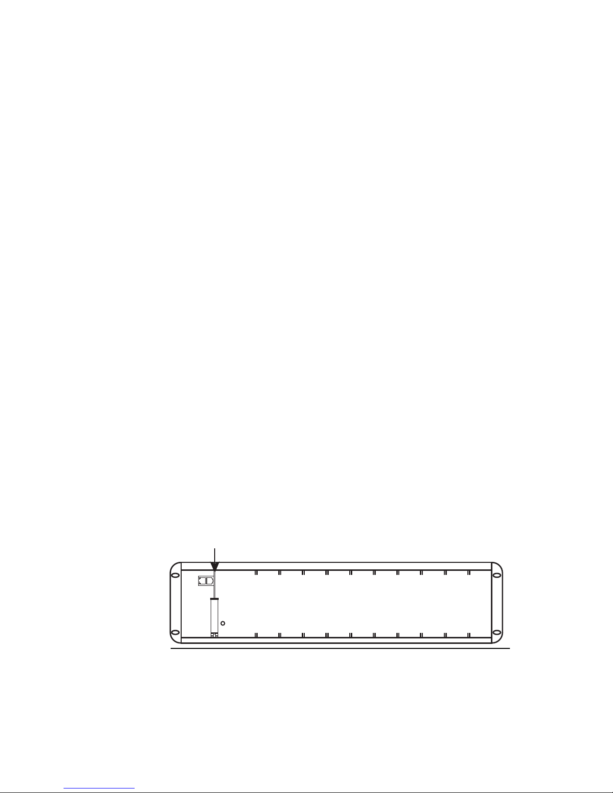
2. Carefully insert the network switch card into the Rack. You
must insert it into the left-most slot, as shown in Figure 2 on
page 12.
Network switch card
Figure 2 Network switch card position in the Rack
3. Power up the Rack.
 Loading...