

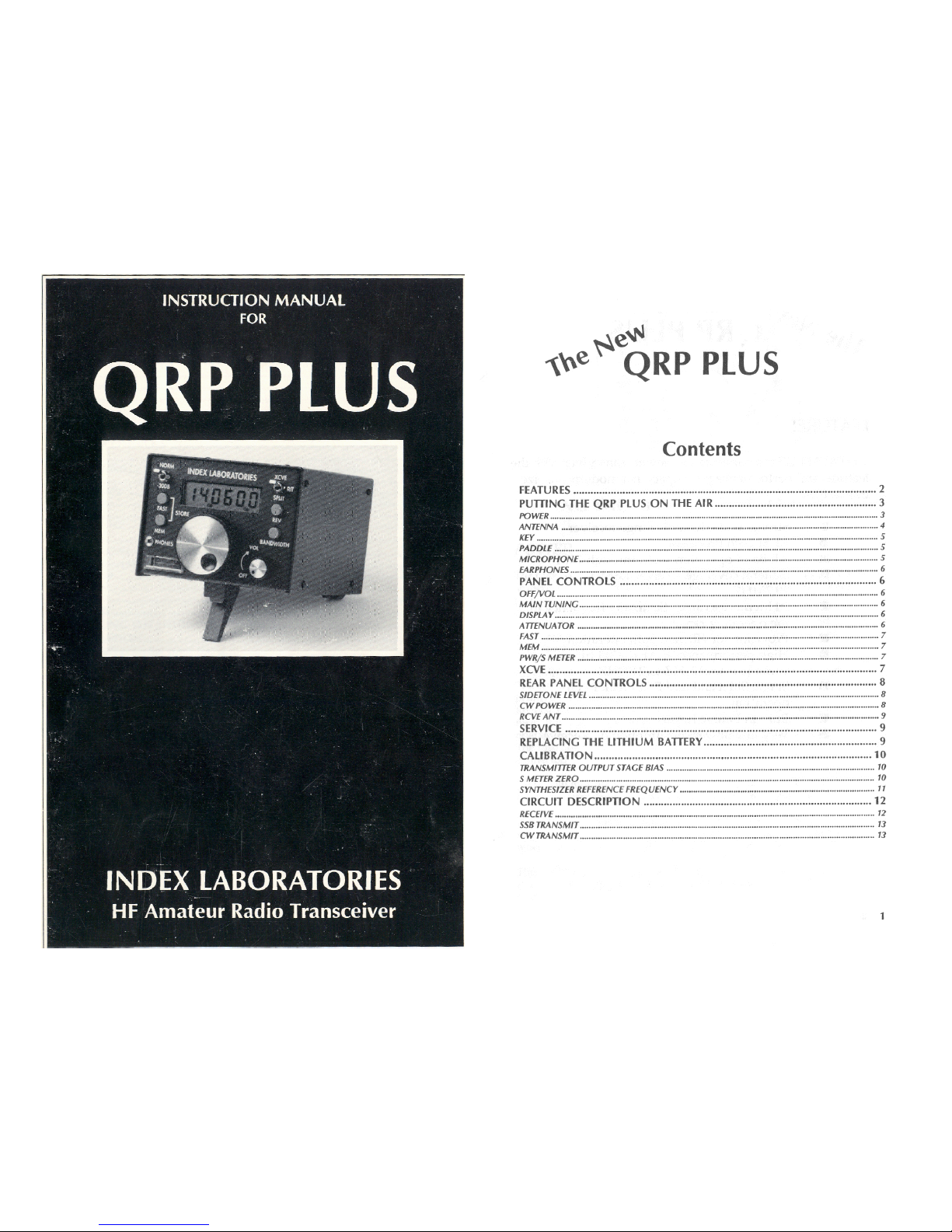
INDEX LABORATORIES
HF Amateur Radio Transceiver
the QRP PLUS
Contents
FEATURES
2
PUTTING THE QRP PLUS ON THE AIR
3
POWER
3
ANTENNA
4
5
PADDLE
5
MICROPHONE...
5
EARPHONES
6
PANEL CONTROLS
6
OFF/VOL
6
MAIN TUNING
6
DISPLAY
6
ATTENUATOR
6
FAST
7
MEM
7
PWR/S METER
7
XCVE
7
REAR PANEL CONTROLS
8
SIDETONE LEVEL
8
cw
POWER
8
RCVE ANT
9
SERVICE
9
REPLACING THE LITHIUM BATTERY
9
CALIBRATION
10
TRANSMITTER OUTPUT STAGE BIAS
10
S METER ZERO
10
SYNTHESIZER REFERENCE FREQUENCY
11
CIRCUIT DESCRIPTION
12
RECEIVE
12
SSB TRANSMIT
13
CW TRANSMIT
13
INDEX LABORATORIES
HF Amateur Radio Transceiver
the QRP PLUS
Contents
FEATURES
2
PUTTING THE QRP PLUS ON THE AIR
3
POWER
3
ANTENNA
4
5
PADDLE
5
MICROPHONE
5
EARPHONES
6
PANEL CONTROLS
6
OFF/VOL
6
MAIN TUNING
6
DISPLAY
6
ATTENUATOR
6
FAST
7
MEM
7
PWR/S METER
7
XCVE
7
REAR PANEL CONTROLS
8
SIDETONE LEVEL .-
8
cw
POWER
8
RCVE ANT
9
SERVICE
9
REPLACING THE LITHIUM BATTERY
9
CALIBRATION
10
TRANSMITTER OUTPUT STAGE BIAS
10
S METER ZERO
10
SYNTHESIZER REFERENCE FREQUENCY
11
CIRCUIT DESCRIPTION
12
RECEIVE
12
.5.513 TRANSMIT
13
CW TRANSMIT
13
vhe
N
eNt4
QRP PLUS
FEATURES
The QRP PLUS is a compact low power transceiver with the
features and performance you expect in a modern full size
transceiver.
■
Strong, wide dynamic range receiver
■
RF Speech Processor
■
All Band operation 160M through 10M
■
General coverage receiver 1.8MHZ to
29.7MHZ
■
20 Memories can be Set to any frequency in
the operating range
■
Provision for efficient Split operation
■
High performance SCAF digital filters
variable from 100HZ to 2400HZ
■
Single Sideband and Full Break in CW
operation
■
Built in Iambic Keyer
■
Very low power consumption on Receive
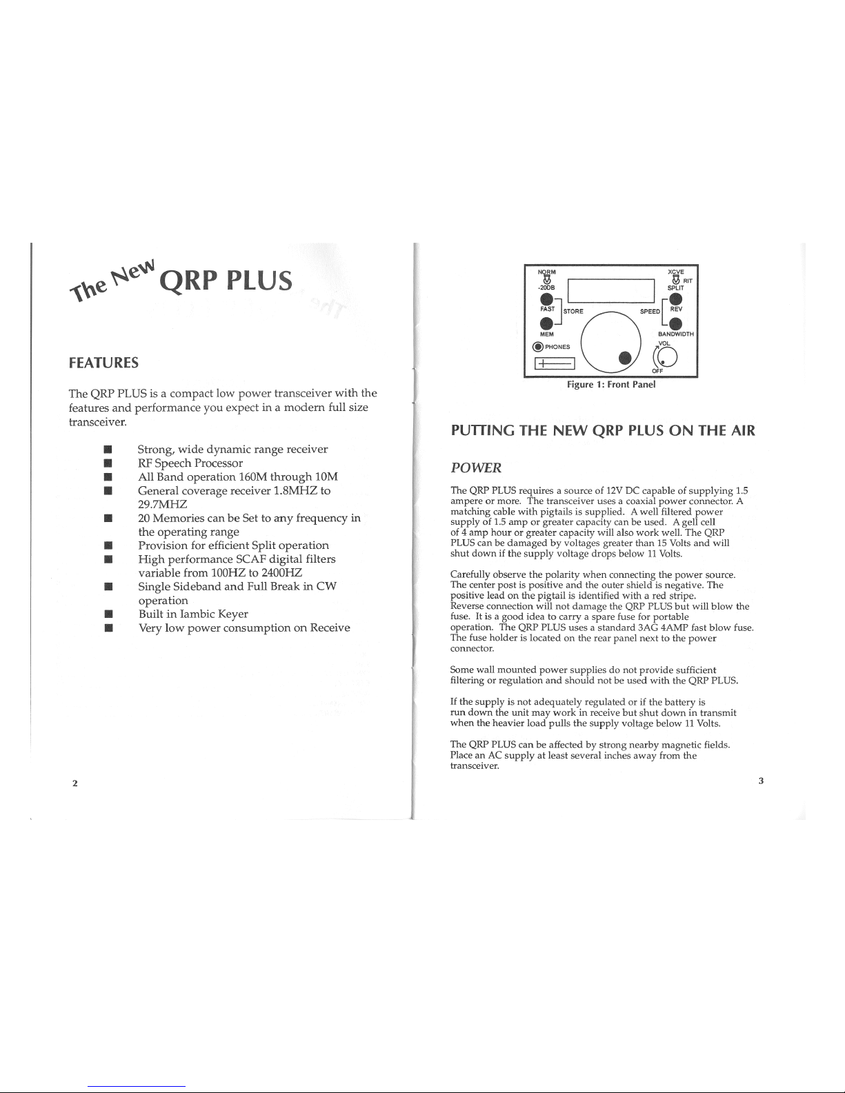
Figure 1: Front Panel
PUTTING THE NEW QRP PLUS ON THE AIR
POWER
The QRP PLUS requires a source of 12V DC capable of supplying 1.5
ampere or more. The transceiver uses a coaxial power connector. A
matching cable with pigtails is supplied. A well filtered power
supply of 1.5 amp or greater capacity can be used. A gell cell
of 4 amp hour or greater capacity will also work well. The QRP
PLUS can be damaged by voltages greater than 15 Volts and will
shut down if the supply voltage drops below 11 Volts.
Carefully observe the polarity when connecting the power source.
The center post is positive and the outer shield is negative. The
positive lead on the pigtail is identified with a red stripe.
Reverse connection will not damage the QRP PLUS but will blow the
fuse. It is a good idea to carry a spare fuse for portable
operation. The QRP PLUS uses a standard 3AG 4AMP fast blow fuse.
The fuse holder is located on the rear panel next to the power
connector.
Some wall mounted power supplies do not provide sufficient
filtering or regulation and should not be used with the QRP PLUS.
If the supply is not adequately regulated or if the battery is
run down the unit may work in receive but shut down in transmit
when the heavier load pulls the supply voltage below 11 Volts.
The QRP PLUS can be affected by strong nearby magnetic fields.
Place an AC supply at least several inches away from the
transceiver.
2
3

POWER (1:::)
~
RAU`.11lT
ANT
0 0
SIDE
TONE MIC
ER
° 0 0
PADDLE KEY
0
0
NO CONNECTION
GND
GND
MIC
QRP ANT SWR
ANT
PLUS
BRIDGE
TUNER
Figure 2: Rear Panel
Additional power connectors are available from Index Laboratories
and may also be ordered from Mouser Electronics as P/N 172-4201
2.5mm X 5.5mm split pin power cable assembly.
ANTENNA
KEY
A 3.5 mm phone jack is provided for the key. The key sees +5
Volts at a few milliamperes. The QRP PLUS is set up for full
break in operation and transmits when the key is closed. A
sidetone is also activated. If the QRP PLUS is tuned to a
frequency outside the amateur bands it will not transmit when the
key is closed.
PADDLE
A 3.5mm stereo jack is provided for the keyer paddle.
Connections are shown in Fig. 4. The tip connects to the dot
paddle and the sleeve connects to the dash paddle.
Figure 4: Paddle Connections
0
3.5 mm Stereo Connector
Successful QRP operation requires a reasonably efficient and well
matched antenna. The QRP PLUS expects a 50 ohm matched load.
Excellent results can be obtained with a 60 foot or longer random
wire if a suitable antenna tuner is used. The tuner, SWR bridge
and antenna should be connected as shown in Fig. 3. A good
ground or counterpoise is important in the use of random wire
antennas. Many excellent books are available for more refined
antenna designs.
Unlike most solid state transmitters the QRP PLUS is not readily
damaged by mismatch and does not shut itself down under high SWR
mismatched conditions. However, intentional operation under
mismatched conditions should be avoided. It is possible that the
unit can generate spurious signals under certain extreme
mismatched conditions.
The antenna connection is a standard SO-239 connector as shown in
Fig. 2, rear panel.
Figure 3: Antenna Example
ANTENNA 60'
END FED WIRE
"- OR LONGER
COUNTERPOISE
♦
GROUN
D
GND
DASH DOT
MICROPHONE
The New QRP PLUS is designed for use with electret type microphones.
The icom HM-65 and MFJ 285W can be used without modification.
Many other microphones may be used if the connector is rewired
appropriately. See Figure 5 for plug wiring details.
Figure 5: Microphone Connections
5
4

EARPHONES
Standard stereo headphones with 3.5mm stereo plug of the type used
with walkmen etc. are used. When the phones are plugged in the
speaker is disconnected.
PANEL CONTROLS
(See Fig. 1, Front Panel)
OFF/VOL
The off/volume control switches power to the QRP PLUS and
controls the loudness of received signals. The serial number of
each unit is stored internally and will flash briefly on the
display each time the QRP PLUS is turned on.
MAIN TUNING
The main tuning control serves a number of functions. It sets
the frequency of operation. When the MEM button is pressed, the
main tuning control steps from one stored frequency to the next.
When the BANDWIDTH button is pressed it sets the receiver
bandwidth and when the BANDWIDTH and REV buttons are pressed
simultaneously it sets the keyer speed. In each case the
frequency, bandwidth or speed is indicated on the LCD display.
DISPLAY
The LCD display shows frequency in 100HZ resolution although
actual tuning is done in approximately 10HZ increments. In SPLIT
or RIT modes the receive frequency is displayed when receiving
and the transmit frequency is displayed when transmitting. Press
the REV button to read the transmit frequency without going on
the air. When the BANDWIDTH button is pressed the display shows
bandwidth in 100HZ steps. When the keyer speed buttons are
pressed the display shows the speed in words per minute.
ATTENUATOR
The attenuator switch can be used in the -20DB position to deal
with unusually strong signals or high band noise. It is usually
left in the NORM position.
FAST
The normal tuning rate is about 4KHZ per revolution. For rapid
movement from one frequency to another the FAST button can be
pressed while tuning. The fast tuning rate is about 100KHZ per
revolution.
MEM
The QRP PLUS has 20 memories. It comes from the factory with the
memories preset to a few frequencies in each amateur band. Any
memory can be changed to any frequency desired. Press the MEM
button and tune to the memory you wish to change. Tune to the
new frequency using the FAST button if the new frequency is some
distance from the old. Press the FAST button and hold while
pressing the MEM button. The new frequency is now stored in the
current memory.
The memories are retained with the use of an internal lithium
battery. If for any reason the memories are lost they can be
returned to the factory presets by holding the MEM button down
while turning power on.
It is possible to toggle between two frequencies through use of
the MEM button. For example, suppose you want to check a net
frequency periodically while operating elsewhere in the band.
Press the MEM button and the frequency will change to the current
memory frequency. Tune to a new frequency. If you press the MEM
again you will return to the stored frequency but if you press it
once more you will return to the last used frequency. Each time
you press MEM you will alternate between the current memory and the
frequency last used.
PWR/S METER
The power/s meter indicates signal strength in receive and
relative output in transmit.
XCVE
The receiver is general coverage and can be tuned to any
frequency between 1.8MHZ and 29.7MHZ. The transmitter will not
operate if the frequency is set outside the amateur bands.
Inside the amateur bands it is the operator's responsibility to
transmit only on modes and frequencies consistant with his or her
class of license.
7
6

In the XCVE position the QRP PLUS receives and transmits on the
same frequency.
Switch to RIT and the transmit frequency remains fixed while the
receive frequency can be varied. Push the REV button while in RIT and
the transmit frequency will be displayed and can be tuned while the
receive frequency remains fixed. (XIT)
Working Split:
The DX station is listening up 5KHZ.
1 Tune in the DX station with the switch in the XCVE position.
2 Switch to SPLIT.
3 Press and hold the REV button while tuning to listen for other
stations calling the DX.
4 When you have found the DX station's listening frequency,
release the REV button and call. You will be transmitting on his
listening frequency and listening on his transmitting frequency.
BANDWIDTH / MODE
Press the bandwidth button and the digital filter bandwidth will be
displayed. It can be varied from .1 khz to 2.4 khzwith the main tuning
knob.
If the display shows SSB the frequency readout will be accurate for SSB
signals. If the display shows CW, the frequency will be accurate for CW
signals. To change from SSB to CW or back press the FAST button while
holding the BANDWIDTH button.
REAR PANEL CONTROLS (see
Fig. 2
Rear
Panel)
SIDETONE LEVEL
This control adjusts the loudness of the CW sidetone relative to
received signals. The sidetone level also tracks the front panel
volume control. The sidetone level should be adjusted to suit
your personal preference.
TRANSMIT POWER
The TRANSMIT POWER control adjusts the transmitter output power
in both SSB and CW modes. The power can be varied smoothly from
milliwatts to more than five watts. The power for a given setting will
remain approximately constant from band to band.
8
SERVICE
A one year warranty is provided with the QRP PLUS. Terms are
detailed on the warranty card provided with the unit.
Service is provided at the factory. Please call the factory
prior to returning a unit for service. You pay shipping to the
factory. We pay return shipping on warranty service.
Opening or modifying a QRP PLUS transceiver does not
automatically void the warranty. However, if, in the judgement
of Index Laboratories a malfunction is the result of abuse or
modification of the unit, service will be billed at standard
rates.
When returning a unit please pack carefully using original
packing material where possible.
Index Laboratories will make every effort to provide qualified
technical support by telephone and can, when appropriate, provide
replacement components or assemblies.
REPLACING THE LITHIUM BATTERY
The memories are retained through the use of a lithium battery.
It is a type 2016 "coin
cell"
battery widely available as a
calculator and camera replacement.
1 Remove the top cover. Be careful not to stress the speaker leads.
2 The lithium battery is clearly visible from the top near the back
of the second PCB. See Fig. 7. It is a coin type about the size
and shape of a nickel.
3 Use a small screwdriver to lift and slide out the old battery.
4 Slide in the replacement. Make sure the side marked + is facing
up.
5 Replace the top cover.
6 Hold in the MEM button while turning power on to restore the
factory presets to the memory.
Figure 7: Lithium Battery (Top view, rear of unit)
tr-2
()11
01
O
lithium Battery
9

CALIBRATION
TRANSMI
ER OUTPUT STAGE BIAS
Equipment Needed: Ammeter 0-2 amps connected to measure the
current drawn from the 12V supply.
Adjust: Transmitter BIAS pot (R18) on XMTR PCB. (Bottom board on
the stack) See Figure 17. The pot is accessable from the side of
the board.
The jump occurs over a very small movement of the tuning dial.
Practice until you can set the tuning to the closest point on
either side of the frequency jump. Listening to a carrier from a
signal generator can be helpful.
If the unit needs calibration, the trimmer capacitors should be
set so that the two frequencies are 4,000,312 and 4,000,493 HZ.
The capacitors interact and the adjustments must be made slowly
to obtain accurate results.
CIRCUIT DESCRIPTION
1 Set the Transmit Power control to its lowest setting. (fully
counter clockwise)
2 Set the XMTR BIAS control (R18 on XMTR PCB) fully clockwise.
3 Close key and read the current from the 12V supply. It should be
approximately 450 MA
4 Adjust R18 (BIAS) to read a total current of about 600MA.
S METER ZERO
Adjust: R31 on the AF PCB (3rd from bottom on the stack). See
Figure 11. The pot is accessable from the side of the PCB. With no
antenna connected, adjust R31 (S Meter Zero) for a
reading of zero on the S meter.
SYNTHESIZER REFERENCE FREQUENCY
Caution: The accuracy of the displayed frequency and correct
tuning depend on the precision of this adjustment. We suggest
you perform this adjustment only if necessary and work with
particular care to ensure accuracy.
Equipment Needed: Frequency counter with 1HZ resolution, Signal
Generator
Adjust: LO PCB, Second board from bottom of stack. See Figure 9,
C47 and C48 trimmer capacitors
1.
Tune the QRP PLUS to 7.300.0 MHZ.
2.
Connect the frequency counter to U4 (MC145156) Pin 17
(located near the trimmer capacitors).
3.
Slowly turn the main tuning dial. The measured frequency
should go from 4,000,312 HZ to 4,000,493 HZ then drop back to
4,000,312 HZ.
The QRP PLUS uses a single conversion up converting design. The
IF frequency is 50MHZ. Bidirectional circuitry is used in the IF
and filter chain.
Selectivity is provided by a 6 pole crystal ladder filter at
50MHZ and variable SCAF digital filters at audio.
The synthesizer is a single loop design. The basic synthesizer
uses 2KHZ steps with intermediate steps of approximately 10HZ
obtained through direct microprocessor control of the reference.
RECEIVE
(SEE BLOCK DIAGRAM FIG. 8)
An incoming signal is routed through the transmit/receive relay
to the front panel attenuator. The attenuator can insert a 20DB
resistive pad in the signal line. From the attenuator, the
signal passes through a high pass and a low pass filter to the
INDEX-1 high performance diode ring double balanced mixer. The
mixer converts the incoming signal to an IF frequency of 50MHZ.
The synthesizer has three voltage controlled oscillators covering
the following ranges:
42.7MHZ - 48.2MHZ
57.3MHZ - 68MHZ
68MHZ - 79.7MHZ
The lower range corresponds to incoming signals from 1.8MHZ to
7.3MHZ. The lower range is below the 50MHZ IF while the higher
ranges are above the IF. In conjunction with the crystal filter
this provides lower sideband operation below 7.3MHZ and upper
sideband operation above 7.3MHZ.
The VCO's are selected under microprocessor control and the VCO
10

output is buffered, amplified and applied to the balanced mixer.
The synthesizer uses a Motorola 145156 IC and a dual modulus
prescaler. The reference frequency is 4MHZ. The synthesizer
uses 2KHZ steps. Intermediate steps of approximately 10HZ are
provided by controlling the reference frequency with a D/A
converter from the microprocessor. The microprocessor controls
the synthesizer and D/A to provide smooth, continuous tuning
across the frequency range.
The 50MHZ IF signal goes through a strong amplifier and an
attenuator to a 6 pole crystal filter. The crystal filter is set
to 2.4KHZ bandwidth and its principle function is to reject the
opposite sideband. Overall receiver bandwidth and filter shape
factor are established by the variable digital audio filters.
From the crystal filter the signal passes through a low noise
preamplifier and a MC1350 IF amplifier which also provides AGC
control. The product detector is an SBL-1 diode ring balanced
mixer.
this point the CW and SSB signals follow the same path.
Also operating under microprocessor control are the sidetone and
keyer functions.
The IF and mixer are bidirectional, that is, the transmit signal
passes through the same stages in the reverse direction as the
receive signal. First the crystal filter, the attenuator pad, a
broadband amplifier, the INDEX-1 mixer and the filters.
The remainder of the transmitter consists of four broadband gain
stages building the signal to five watts output. The transmitter
output stage is a power MOSPEI followed by a bank of 6 low pass
filters and the reed relay antenna switching circuit.
A panel meter reads AGC level in receive and relative RF output
on transniit.
The signal is routed through an audio preamplifier to the SCAF digital
filters, first the HPF then the LPF. The filter cutoff
frequencies are set by the microprocessor. After filtering the
signal is routed to both the audio output amplifier and the AGC
amplifier.
The AGC amplifier has switching and storage functions to ensure
smooth CW break in operation.
SSB TRANSMIT
The signal from the microphone is amplified by VOGAD circuit. The
gain is automatically set to the correct value, compensating for different
microphones and voices. The audio is applied to a balanced modulator
and the resulting SSB is routed to a limiter which provides RF speech
processing. A wide range ALC circuit further increases average power.
CW TRANSMIT
When the key is closed, the microprocessor performs all the
switching functions with appropriate delays to ensure smooth
break in operation. A voltage, set by the CW power control is
applied to the SSB balanced modulator while the BFO frequency is
shifted down 650HZ to the center of the passband. This creates a
50MHZ carrier whose level is set by the CW power control. From
12
13

•RP
PLUS
BLOCK
O
L
OOMP
PI
O
FIGURE 8: BLOCK DIAGRAM
15
 Loading...