

1104850
2017-10-25
EN
Servicemanual
www.indexator.com
ROTATOR
XR 500
XR 500 C
XR 600
XR 600 C
IMPORTANT!
Read through the service manual carefully and make
sure that you understand the content
before starting the service.

2
1104850 2017 10 25 © Indexator Rotator Systems AB
GENERAL
This service manual has been produced inhouse Indexator and can show the special tools and equipment
that are used in the production. Alternative equipment can also be used.
Vi are contstantly improving our products and reserve the right to make design changes without introducing
them on products that have already been delivered.The same applies to maintenance and other service
operations.
The service manual contains instructions for repairing and maintaining your product for long life and fault-
less operation. Before starting repair work on the rotator, read through the manual thoroughly in order to
understand its content. Casual or incorrect actions may result in serious or even life-threatening injury.
Servicing work may only be done by personnel familiar with Indexator products.
For major renovation work, trained personnel should be contacted.
SAFETY
In addition to the recommendations in this service manual, every country(nation) has its own safety regula-
tions. If the recommendations in the manual differs from the regulations in your country, you must observe
your national regulations.
Use the necessary safety equipment for the task, for example safety shoes, gloves, safety glasses and
ear protection. Use gloves as protection against oil, grease and other noxious substances.
3
1104850 2017 10 25 © Indexator Rotator Systems AB
Description
XR is a compact rotator with grapple- and rotation function. C models has an extra function for central greasing.
That function is describes as a notication ”only C model” in the servicemanual.
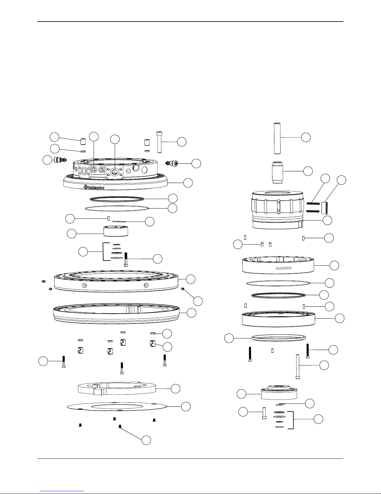
Components
The components referred to in the servicemanual.
This is a XR 600.
16
24
19
8
9
30
3
16
4
20
6
30
27
25
13
28
11
23
24
10
12
23
22
1
21
7
29
17
2
30
16
18
15
14
5
30
31
32
30
30
30
30
26

4
1104850 2017 10 25 © Indexator Rotator Systems AB
Pos Detalj nr Ant Beskrivning Description Anm Åtdragn mom
Fig Part no Qty Notes Torque
8600 000 Rotator XR 600 Rotator XR 600 Compl
1 8100 201R 1 Stator övre Stator plate upper Incl pos. 22, 25, 31, 32
2 8100 222 1 Statorring Stator frame
3 8100 225 1 Rotor Rotator shaft
4 8100 207 1 Stator nedre Stator plate lower
5 8100 054 2 Käglor Restrictors
6 8100 078 1 Block svivel övre Block upper
7 8100 081 1 Block svivel nedre Block lower
8 8100 084 1 Rör svivel inre Internal tube
9 8100 053 1 Rör svivel yttre Outer tube
10 8100 099 1 Medbringare Transmission
11 8100 213R 1 Fästplatta Lower link
12 8100 093 1 Bottenplåt Bottom plate
13 8100 167R 1 Svängkranslager Slewing bearing Incl pos. 28
14 8000 337 12 Vinge Vane
15 5006 030 24 Fjäder Spring
16 1019 900 6 Pinne Solid pin 8x20
17 1010 677 20 Skruv Screw M12x110 120 Nm
18 1074 715 1 Tätning avstrykare Wiper seal
19 1078 179 3 Skruv Screw M8x50 33 Nm
20 1074 541 9 Skruv Screw M10x60 60 Nm
21 1014 950 5 Skruv Screw M12x45 120 Nm
22 6002 565 2 Tryckbegr ventil Relief valve 28 MPa 40 Nm
23 1074 574 6 Mutter Nut M12
24 1066 851 6 Pinne Tubular pin 22x30
25 1078 914 2 Tryckbegr ventil Relief valve 38 MPa 60 Nm
26 1070 556 4 Skruv Screw M8x12
27 1008 069 30 Skruv Screw M16x90 333 Nm
28 1018 258 6 Smörjnippel Grease nipple M8x1
29 1070 861 2 Skruv Screw M8x65 33 Nm
30 6002 465 1 Tätningssats Seal kit XR500/XR600
31 5001 384 2 Propp Plug G1/2
32 5001 385 2 Propp Plug G3/4
5
1104850 2017 10 25 © Indexator Rotator Systems AB
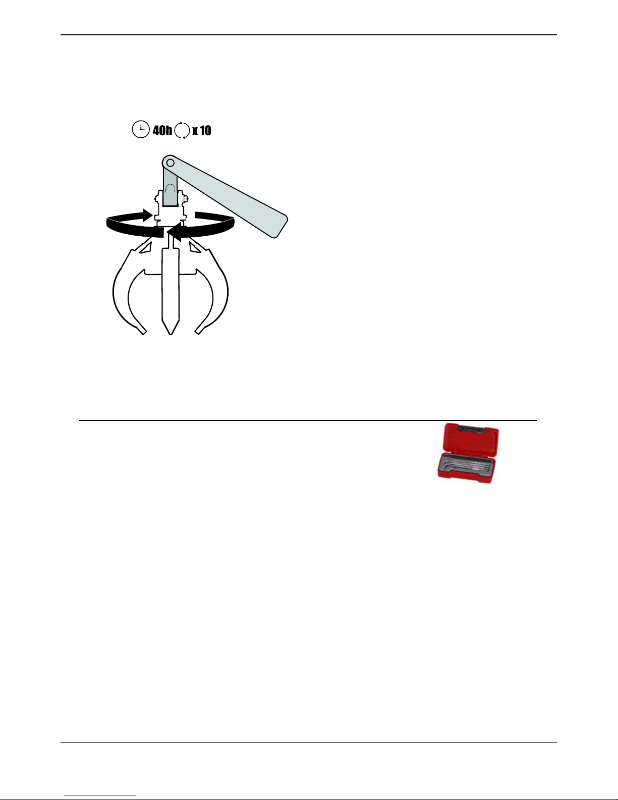
To prolong the lifetime:
Every 40 hours rotate 10 rounds.
Recommended tools
PART NO DESCRIPTION QTY
1077 106 Glide seal remover 1 pcs
6
1104850 2017 10 25 © Indexator Rotator Systems AB
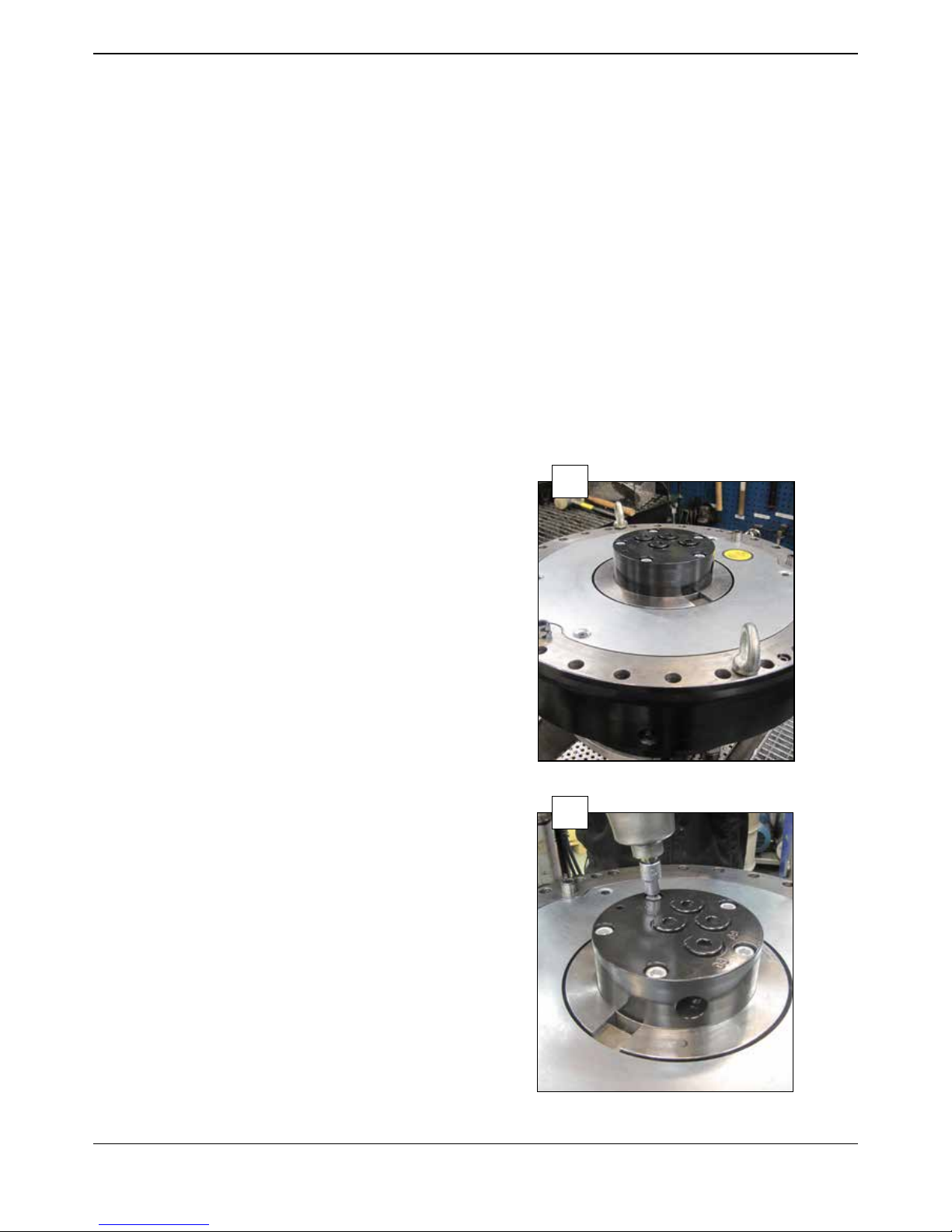
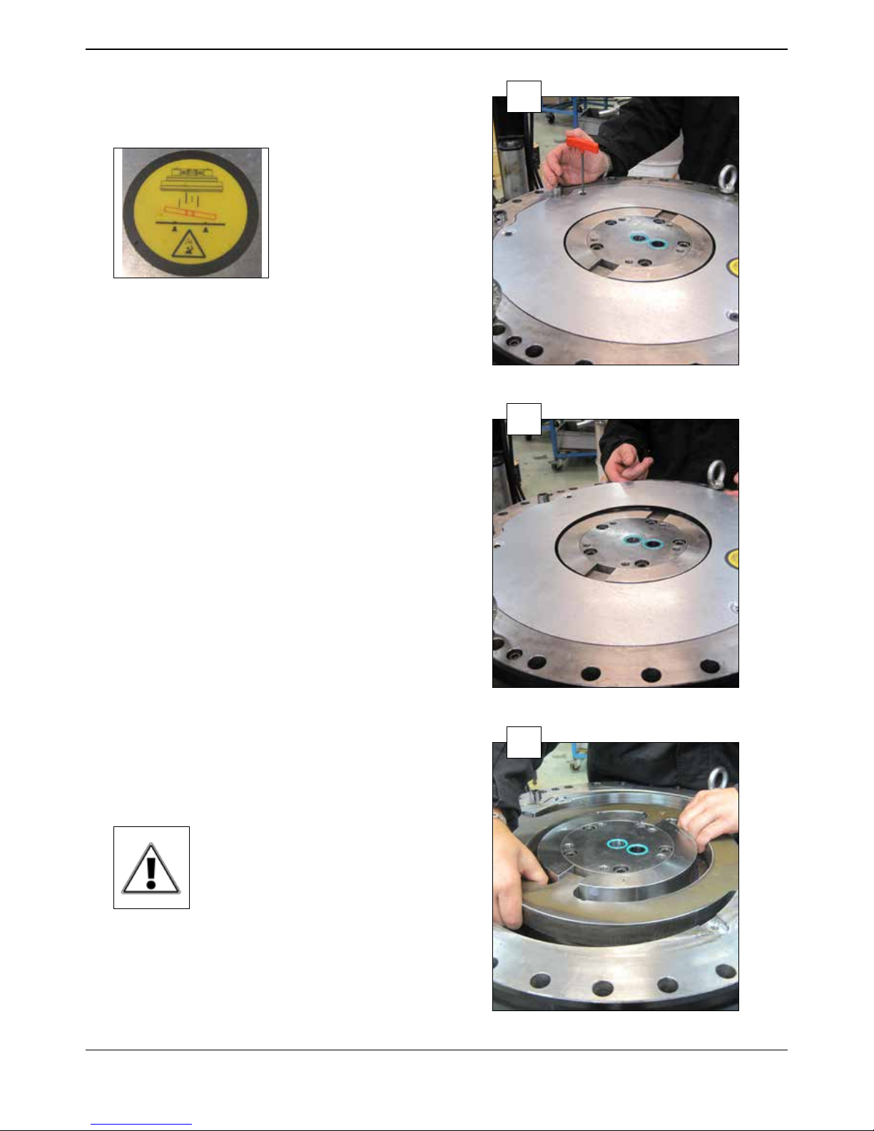
Put the rotator upside down and remove the manifold
block.
1
Remove the manifold block by loosen 5 pcs of M12
screws.
2
Changing seals
Contents
This servicemanual describes:
Changing seals......................................................................................................................................................6-29
Changing bearing..............................................................................................................................................30-36
7
1104850 2017 10 25 © Indexator Rotator Systems AB
WARNING! If the rotator is normally positioned the
transmision can fall down if the bottom plate is loosened!
Remove the bottom plate by loosen 4 pcs of
M8x12 screws.
3
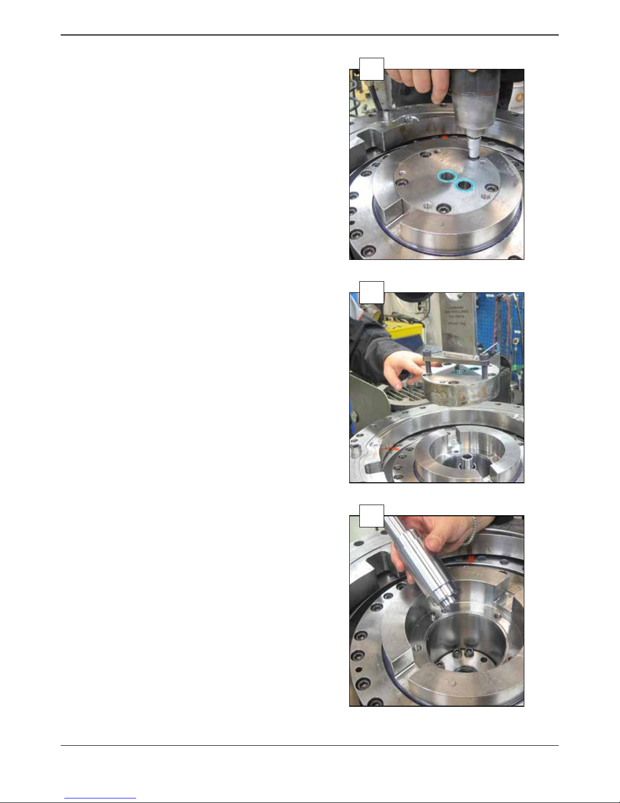
Lift up the bottom plate.
4
Lift up the transmission.
Newer versions of transmission has two M10 holes.
Use 2 pcs of M10 screws to create a good grip and
prevent any risk of injury.
NOTE! Risk of injury!
5
8
1104850 2017 10 25 © Indexator Rotator Systems AB
Remove 5 pcs of M12x45 screws in block lower.
6
LIft up block lower.
7
Remove the outer tube.
Remove the internal tube.
8
9
1104850 2017 10 25 © Indexator Rotator Systems AB
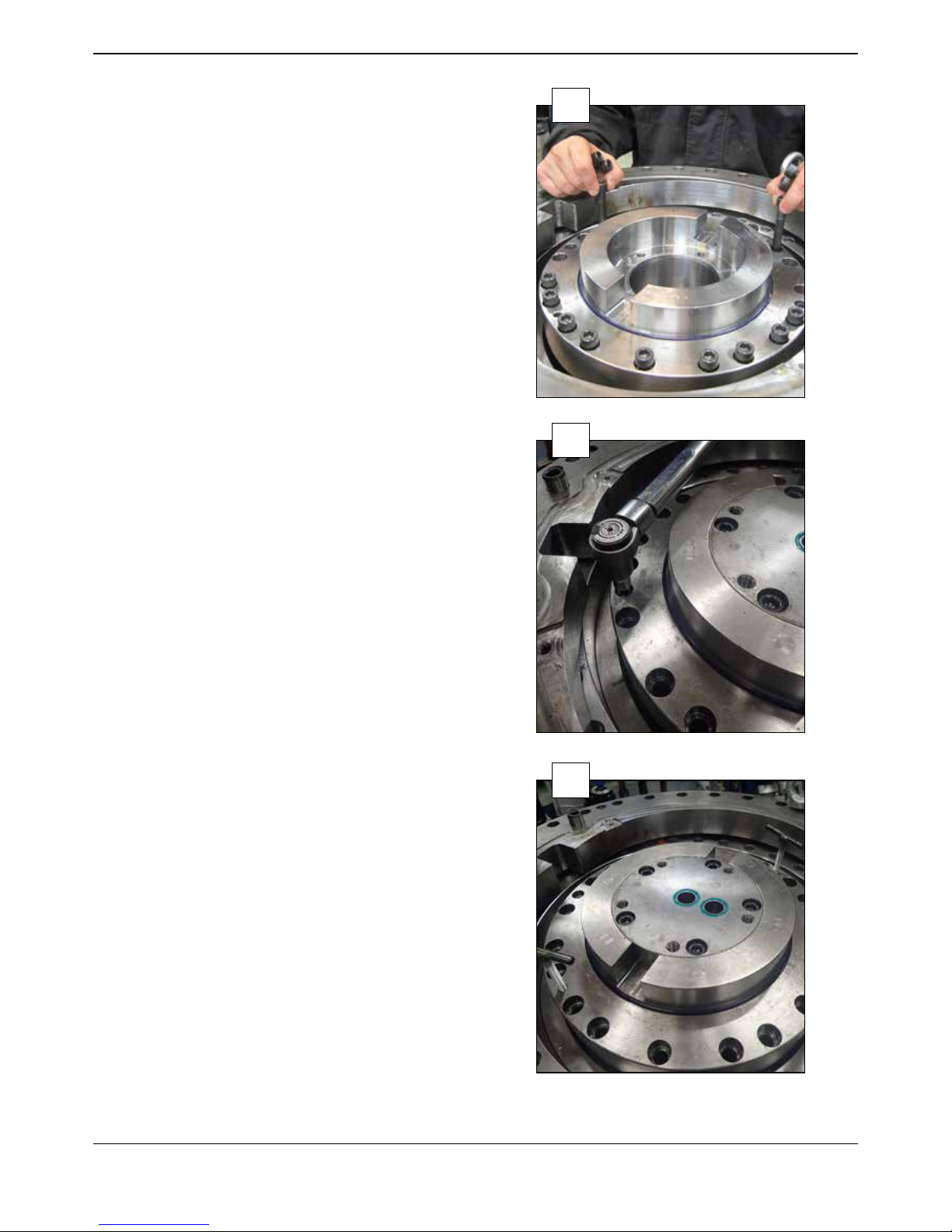
Remove 20 pcs of M12x110 screws to loosen the motor
part.
9
Remove 2 pcs of M8x65 screws - holding the motor parts
together.
10
Remove stator plate lower.
Assemble 2 pcs of M8 screws, with the total thread length
85 mm. That will lift the stator lower plate from the stator
frame.
11
10
1104850 2017 10 25 © Indexator Rotator Systems AB
Remove the stator plate lower.
12
If needed remove the wiper seal (only if it has a damage).
The wiper seal is ordered separately, is not part of the seal
kit.
The wiper seal is only for XR500 and XR600
(not for c-models).
13
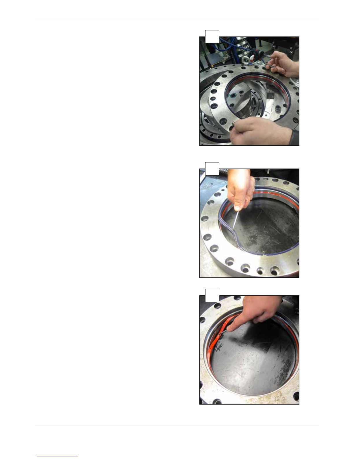
Remove the seal in stator plate lower.
14
11
1104850 2017 10 25 © Indexator Rotator Systems AB
Clean the seal seat thoroughly, using cotton buds and oil
for example.
15
Assemble a new seal.
16
Assemble a new wiper seal (not for c-models).
17

12
1104850 2017 10 25 © Indexator Rotator Systems AB
Only for C model.
Remove 2 pcs of seals in stator plate lower, clean the seal
seats and assemble new seals.
Grease the seals on the inside surface.
19
Remove the o-ring from the stator frame.
20
18

13
1104850 2017 10 25 © Indexator Rotator Systems AB
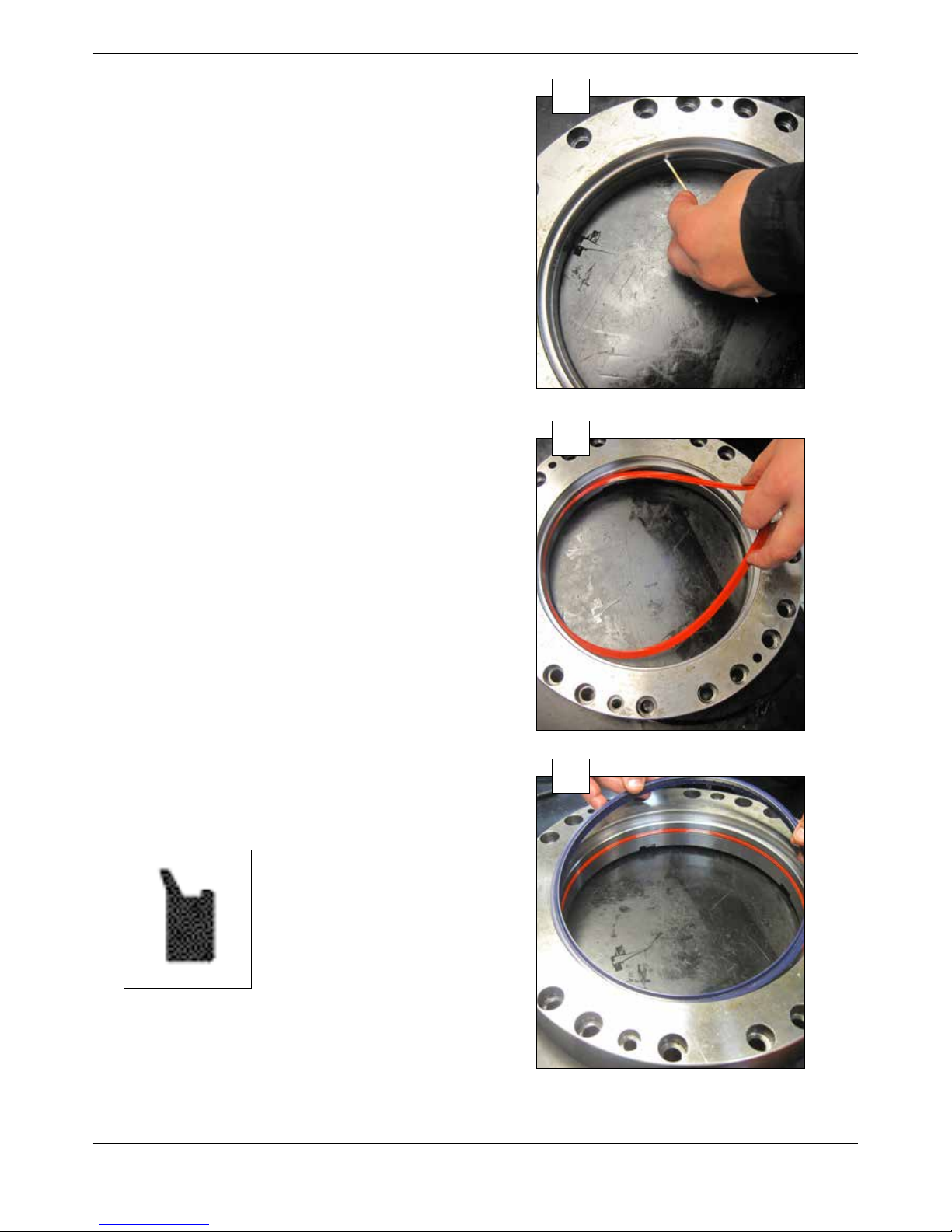
Clean the seal seat.
21
Lubricate the seal seat with oil.
22
Assemble a new o-ring.
23

14
1104850 2017 10 25 © Indexator Rotator Systems AB
Only for C-model.
Remove the o-ring for the C-channel.
Clean the seal seat.
Assemble a new o-ring.
24
Assemble stator plate lower on the motor part.
Assemble 2 pcs of M8 screws with total thread length of
85 mm. Make sure that they do not go through the part
on the back side.
25
Make sure that the holes in stator plate lower aligns
with the two holes for M8x65 screws in the stator frame.
26
15
1104850 2017 10 25 © Indexator Rotator Systems AB
Knock - with care - the stator plate lower the whole way
down with a plastic mallet.
27
Stator plate lower is in the end position when the wiper
seal is visible.
28
Assemble 2 pcs of M8x65 screws holding the motor parts
together.
Torque 33 Nm.
29
16
1104850 2017 10 25 © Indexator Rotator Systems AB
Disassamble the plugs/ttings from the grapple- and
rotation inlets. That will make it easier to lift the motor off.
30
Lift the motor off from stator upper.
If needed knock carefully with a plastic mallet on the lower
link to release the vacuum.
31
Remove the o-ring in stator upper.
32

17
1104850 2017 10 25 © Indexator Rotator Systems AB
Clean the seal seat.
33
Assemble a new o-ring.
34
Remove the seal in stator upper.
35

18
1104850 2017 10 25 © Indexator Rotator Systems AB
Clean the seal seat.
36
Assemble a new seal.
37
Only for C model.
Remove the o-ring for the c-channel in stator upper.
Clean the seal seat.
Assemble a new o-ring.
38

19
1104850 2017 10 25 © Indexator Rotator Systems AB
Clean stator upper from oil to make the assembly of the
motor possible.
39
Remove the block upper by loosen 9 pcs of M10x60
screws.
40
Remove the seals in the block upper.
1 pcs of glide seal Ø42 and inside of that 1 pcs of o-ring
Ø47.
41

20
1104850 2017 10 25 © Indexator Rotator Systems AB
1 pcs of glyde seal Ø28 and inside of that 1 pcs of o-ring
Ø31.
42
Clean the seal seats and assemble new seals.
1 pcs of o-ring Ø31 and - outside of that - 1 pcs of glyde
seal Ø28.
1 pcs of o-ring Ø47 and - outside of that - 1 pcs of glyde
seal Ø42.
43
Remove 2 pcs of o-rings at the grapple channels in stator
upper.
Clean the seal seats and assemble new o-rings.
44

21
1104850 2017 10 25 © Indexator Rotator Systems AB
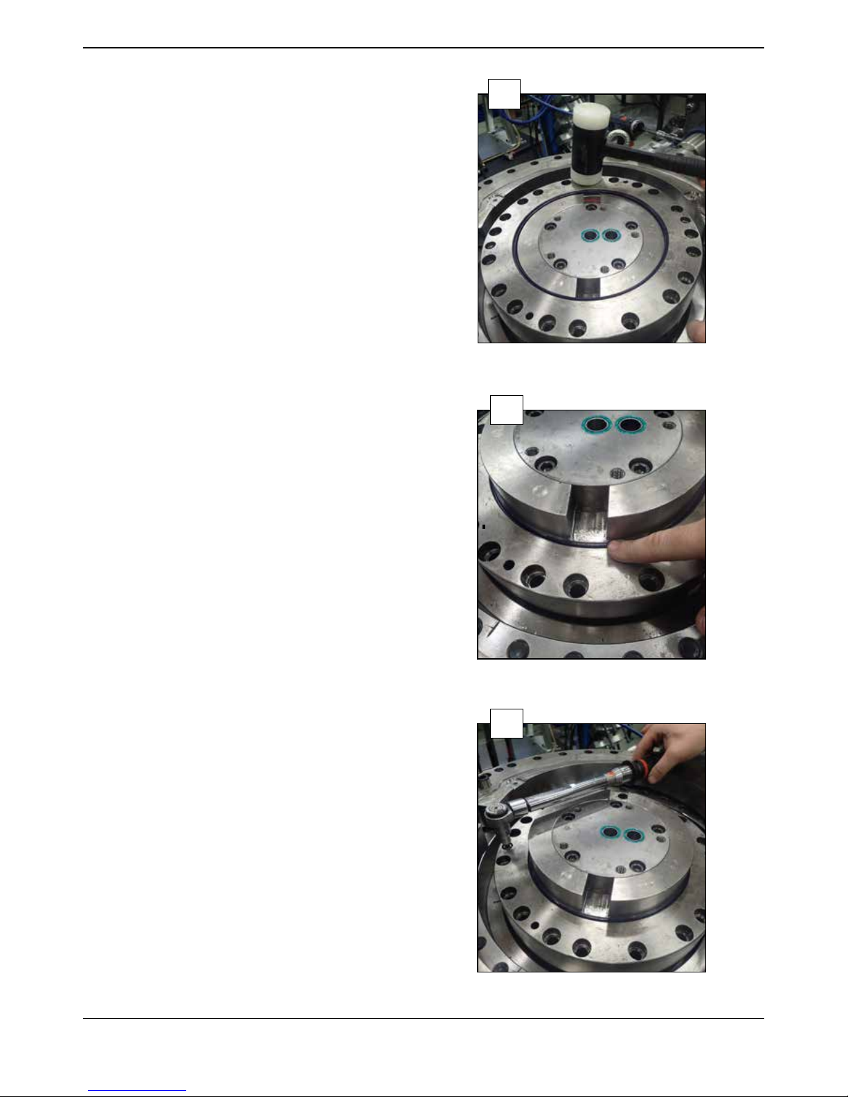
Assemble the block upper in the stator upper.
Note the positions of the
dowel pins.
The block is pressed down by hand.
45
Assemble 9 pcs of M10x60 in block upper.
Crosswise tightening to a torque of 60 Nm.
46
Assemble the motor.
Clean the motor from oil to make the assembly possible.
47

22
1104850 2017 10 25 © Indexator Rotator Systems AB
Note the positions of the rotation channels in the stator
frame.
48
Note the positions of the rotation channels in the stator
upper.
They shall align when assembling the motor part.
Otherwise rotation is not possible.
49
To make the reassembly of the motor easier, make a mark
on the outside of the stator frame where the dowel pins
are positioned.
50

23
1104850 2017 10 25 © Indexator Rotator Systems AB
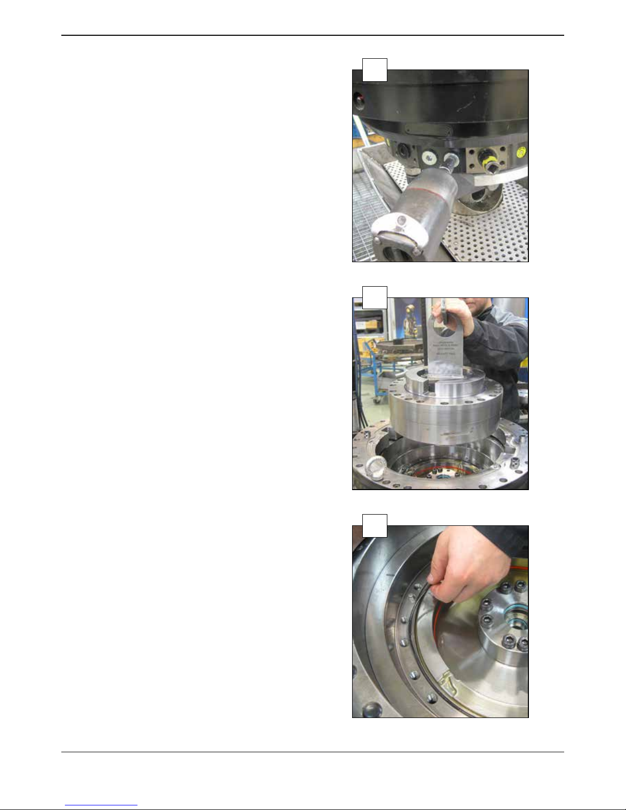
Knock the motor down carefully.
51
Assemble the motor.
Tighten the rst 4 pcs of M12x110 crosswise.
The other 16 pcs of M12x110 can be tightened one by
one.
Torque 120 Nm.
52
Grease the outer tube.
53

24
1104850 2017 10 25 © Indexator Rotator Systems AB
Press down the outer tube by hand till a ”click” sound can
be heard.
54
Grease the internal tube.
55
Assemble the internal tube inside of the outer tube.
Press down the internal tube by hand till a ”click” sound
can be heard.
56

25
1104850 2017 10 25 © Indexator Rotator Systems AB
Grease the edges of the outer tube and the internal tube.
57
Only for C model.
Remove the o-ring for the c-channel on the
rotator shaft.
Clean the seal seat and assemble a new o-ring.
58
Remove the seals in block lower.
Clean the seal seats and assemble new seals.
1 pcs of o-ring Ø47 and outside of that 1 pcs of glyde seal
Ø42.
1 pcs of o-ring Ø31 and outside of that 1 pcs of glyde seal
Ø28.
59
26
1104850 2017 10 25 © Indexator Rotator Systems AB
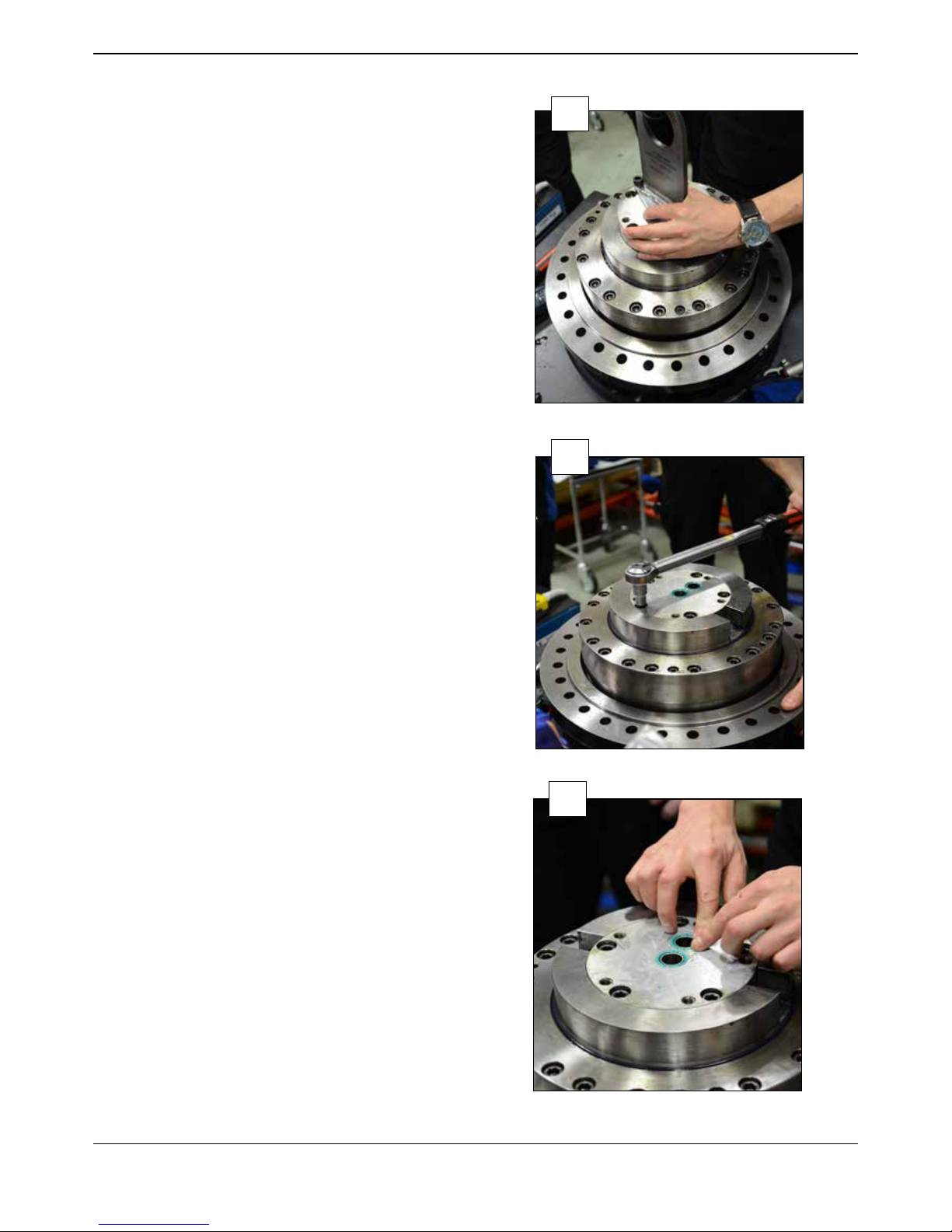
Make a mark on the outside of the rotator shaft and the
block lower where the dowel pins are positioned.
The block lower is in the end position when the upper
surface has the same level as the surface of the rotator
shaft.
60
Assemble 5 pcs of M12x45 screws.
Crosswise tightening to a torque of 120 Nm.
61
Remove 2 pcs of o-rings on the block lower.
Clean the seal seats.
Assemble new o-rings.
62

27
1104850 2017 10 25 © Indexator Rotator Systems AB
Only for C model.
Remove 1 pcs of o-ring for the
c-channel.
Clean the seal seat.
Assemble a new o-ring.
If needed grease the recesses for the transmission in the
lower link.
Grease the recesses for the transmission on the rotator
shaft.
65
63
64

28
1104850 2017 10 25 © Indexator Rotator Systems AB
Assemble the transmission.
Use 2 pcs of M10 screws to create a good grip and
prevent any risk of injury.
Or place the transmission beside the recesses on the
lower link. Turn the bearing so the transmission get the
correct position.
NOTE! Risk of injury!
66
Assemble the bottom plate with 4 pcs of M8x12 screws
to a torque of 16 Nm.
67
Make sure the grapple channels in the manifold block
aligns with the channels in block lower.
68

29
1104850 2017 10 25 © Indexator Rotator Systems AB
Assemble the manifold block with 6 pcs of M12 screws to
a torque of 120 Nm.
69
Test of the rotator function.
Attach the rotation ports (R, R) in stator upper to a
hydraulic powerpack.
Run for 20 seconds in each direction.
Maximum oil ow: 40 l/min
70
Pressure test of the grapple function.
NOTE! The grapple outlets (G, G0) on the manifold
block have to be sealed by steel plugs before testing!
Attach the grapple port G (grapple close) in stator upper
to a hydraulic powerpack. Let port GO (grapple open)
be open. No leakage and the seals are okey.
Pressurize to 20 MPa for 20 seconds.
71

30
1104850 2017 10 25 © Indexator Rotator Systems AB
NOTE! The grapple outlets (G, G0) on the manifold
block have to be sealed by steel plugs before testing!
Attach the grapple port GO (grapple open) in stator upper
to a hydraulic powerpack. Let port G (grapple close)
be open. No leakage and the seals are okey.
Pressurize to 20 MPa for 20 seconds.
72

31
1104850 2017 10 25 © Indexator Rotator Systems AB
Changing bearing
Put the rotator upside down and remove the manifold
block.
73
Remove the manifold block by loosen 5 pcs of M12
screws.
74
WARNING! If the rotator is normally positioned the
transmision can fall down if the bottom plate is loosened!
Remove the bottom plate by loosen 4 pcs of
M8x12 screws.
75

32
1104850 2017 10 25 © Indexator Rotator Systems AB
Lift up the bottom plate.
76
Lift up the transmission.
Newer versions of transmission has two M10 holes.
Use 2 pcs of M10 screws to create a good grip and
prevent any risk of injury.
NOTE! Risk of injury!
77
Remove 3 pcs of M8x50 screws in the lower link.
78

33
1104850 2017 10 25 © Indexator Rotator Systems AB
Lift up the lower link.
79
Remove the 20 pcs of M12x110 screws from the slewing
bearing.
80
Lift the slewing bearing.
81

34
1104850 2017 10 25 © Indexator Rotator Systems AB
Assemble a new slewing bearing.
NOTE!
The guiding edge of the bearing shall be positioned
towards the stator upper.
82
Assemble the 20 pcs of M12x110 screws in the slewing
bearing.
Torque 120 Nm.
83
Assemble the lower link.
84

35
1104850 2017 10 25 © Indexator Rotator Systems AB
Assemble 3 pcs of M8x50 in the lower link.
Torque 33 Nm.
85
Assemble the transmission.
Use 2 pcs of M10 screws to create a good grip and
prevent any risk of injury.
Or place the transmission beside the recesses on the
lower link. Turn the bearing so the transmission get the
correct position.
NOTE! Risk of injury!
86
Assemble the bottom plate with 4 pcs of M8x12 screws
to a torque of 16 Nm.
87

Make sure the grapple channels in the manifold block
aligns with the channels in block lower.
88
Assemble the manifold block with 6 pcs of M12 screws to
a torque of 120 Nm.
89
Fill the bearing with grease using all 6 pcs of grease
nipples on the slewing bearing.
90
Indexator Rotator Systems AB
Box 11, S-922 21 Vindeln, Sweden
Tel +46 933 148 00 Fax + 46 933 148 99
rotator@indexator.com
 Loading...