

Zusatzanleitung:
D
VIDEO-TÜRSPRECHANLAGEFÜR2-FAMILIENHAUS
Moded'emploi supplémentaire:
F
INTERPHONEVIDÉO
POURMAISON BIFAMILIALE
VT37/2Set
X
VT37/2 Set
15VDC
VT37M
VT37C/2
1R 2W 3B 4Y
1
2
1R 2W 3B 4Y
15VDC
VT37M
ExtraGebruiksanwijzingen
NL
VIDEO-INTERCOMSYSTEEM
VOOR2-GEZINSWONING
Additionalmanual:
GB
VIDEODOOR INTERCOMFOR2-FAMILYHOUSE
Istruzioniperfunzionamentosupplementare:
I
IMPIANTODI VIDEOCITOFONOPER CASABIFAMILIARE
1. Einleitung
Lesen Sie diese Bedienungsanleitung
vollständig und sorgfältig durch. Die Bedienungsanleitungen gehören zu
diesem Produkt und enthalten wichtige Hinweise zur Inbetriebnahme und
Handhabung. Beachten Sie immer alle Sicherheitshinweise. Sollten Sie
Fragen habenoder unsicherin Bezugauf dieHandhabung derGeräte sein,
fragen Sie einen Fachmann oder informieren Sie sich im Internet unter
www.indexa.de. Bewahren Siediese Anleitungen sorgfältigauf und geben
Siesieggf.anDritteweiter.
sowie die Anleitung VT37 Set
D
2. BestimmungsgemäßeVerwendung
Diese Video-Türsprechanlage VT37/2 Set besteht aus einer Außenstation
VT37C/2 und zwei Innenstationen VT37M, die jeweils mit einem
vieradrigen Verbindungskabelmit derAußenstationverbundenwerden.Die
jeweiligemaximaleKabellängebeträgt70m.
Die Stromversorgungerfolgtdurchdie mitgeliefertenNetzgeräte,diean die
Innenstationenangeschlossenwerden.
.....
sieheAnleitungVT37Set
3. Lieferumfang
2x InnenstationVT37M(inkl.Wandhalterung)
1x Außenstation VT37C/2
1x Aufputzhalterung
1x Unterputzhalterung
2x Netzgerätmitca.1,8mKabel
8x Montageschrauben
8x Dübel
2x Maschinenschrauben
4. TechnischeDaten /
sieheAnleitungVT37Set(VT37C/2=VT37C)
AußenstationVT37C/2 (sieheAbb. C)
27 KlingeltastemitNamenschild
(Klingeltasteoben.Partei1/Klingeltasteunten:Partei 2)
29 Klemmen(linke4Klemmen:Partei1/rechte 4Klemmen:Partei2)
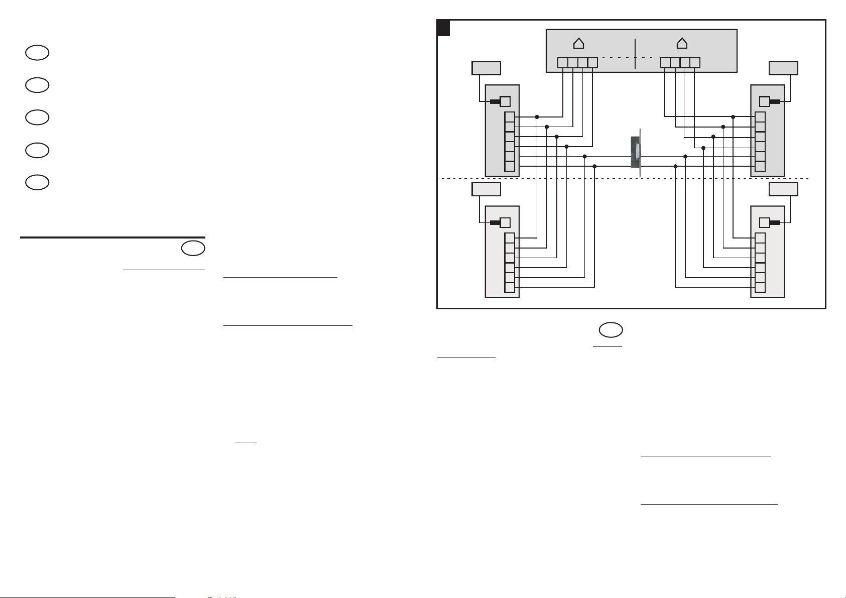
Anschlussdiagramm(siehe Abb.X Seite2)
41 elektrischerTüröffner(optional)
5. Ausstattung
Kapitel6. bis10.
siehe Anleitung VT37Set
11. Anschluss
siehe Anleitung VT37Set
!
Schließen Sie alleGeräte entsprechend derAbbildung XSeite 2 an.
Hinweis:
Verbindung derKlingeltasten zu denKlemmen der Außenstation:
Partei1: Klingeltaste oben - Klemmen links
Partei 2: Klingeltaste unten - Klemmen rechts
Kapitel 12. bis 19
siehe Anleitung VT37Set (VT37C/2 =VT37C)
1R
2W
3B
4Y
5K
6K
15VDC
VT37M
1R
2W
3B
4Y
5K
6K
1. Introduction
Lisez complètement et attentivement cette mode d'emploi
d'emploi du VT37 Set
produit et comportent des informations importantes sur la mise en service
et l'utilisation. Respectez toujours toutes les consignes de sécurité. Si
vous avez des questions ou des doutes sur l'utilisation de cet appareil,
demandez conseil à un spécialiste ou renseignez-vous sur le site Internet
www.indexa.de. Conservez soigneusement cette modes d'emploi et
remettez-les à touteautre personne lorsquenécessaire.
. Les modes d'emploi font partie intégrante du
F
et le mode
2. Utilisation conforme
Cet interphone vidéo VT37 est constitué d'une station extérieure VT37C/2
et de deux stations intérieures VT37M, qui sont reliées chacune par un
câble de connexion à quatre brins à la station extérieure. La longueur
maximale de chaquecâble est de70 m.
L'alimentation électrique est fournie par des adaptateurs compris dans la
livraison qui sontconnectés aux stationsintérieures.
.... voir moded´emploi VT37 Set
3. Contenu de la livraison
2x station intérieure VT37M (avec support mural)
1x station extérieure VT37C/2
(optional)
41
OPTIONAL
1x Support pour applique
1x Support pour encastrement
2x adaptateur avec env.1,8 m decâble
8x vis de montage
8x chevilles
2x vis d'assemblage
1R
2W
3B
4Y
5K
6K
VT37M
1R
2W
3B
4Y
5K
6K
4. Caractéristiques techniques /
5. Équipement
voir mode d'emploiVT37 Set
Station extérieureVT37C/2 (voir illustr. C)
27 Bouton de sonnette avec plaque de nom (Bouton de sonnerie du
haut. Partie1 /bouton de sonneriedu bas :Partie2)
29 Cache bornes (gauche 4 bornes : Partie 1/ droite 4bornes: Partie 2)
Diagramme de raccordement(voir illustr.X)
41 Ouvre-porte électrique (enoption)
(VT37C/2 = VT37C)
Chapitre 6. - 10.
voirmoded'emploiVT37Set
15VDC

11. Connexion
voirmoded'emploiVT37Set
!
ConnecteztouslesappareilsconformémentàlafigureX.
Remarque:
Connexion des boutons de sonnerie [27] aux bornes de la station
extérieure:
Partie1: Bouton desonnerie duhaut-bornesdegauche
Partie2: Bouton desonnerie dubas-bornesdedroite
Chapitre 12. - 19.
voirmoded'emploiVT37Set
1. Inleiding
Neem deze gebruiksaanwijzing
volledig en zorgvuldig door. De gebruiksaanwijzings behoorten
VT37 Set
tot dit product en bevat belangrijke aanwijzingen voor de inbedrijfstelling
en de hantering. Neem de veiligheidsinstructies altijd in acht. Indien u
vragen hebt of als u niet zeker van de hantering van de apparaten bent,
doe dan beroep op een vakman of informeer u op het Internet via
www.indexa.de. Bewaar deze handleidings zorgvuldig en geef ze
eventueel aan derdendoor.
en het gebruiksaanwijzing van de
NL
2. Reglementair voorgeschreven gebruik
Dit videointercomsysteem VT37bestaat uit eenVT37C/2 buitenstation en
twee VT37M binnenstations die telkens met een vieraderige
verbindingskabel aan het buitenstation zijn gekoppeld. De maximale
kabellengtebedraagttelkens70m.
De stroomvoorzieninggebeurtviade meegeleverdenettoestellen die ophet
binnenstationaangeslotenworden.
...ziegebruiksanwijzingenVT37Set
3. Omvang van de levering
2x binnenstation (incl. wandconsole)
1x buitenstation
1x opbouwconsole
1x onderbouwconsole
2x voedingsapparaat met ca.1,8 m kabel
8x montageschroeven
8x plug
2x machineschroeven
4. Technische gegevens/ 5. Uitrusting
zie gebruiksanwijzingen VT37Set
Buitenstation VT37C/2 (zieafbeelding B)
27 Beltoets met naamplaatje (Beltoets boven. Partij 1 /Beltoets onder:
Partij 2)
(VT37C/2 = VT37C)
29 Klemmen (4 linkerklemmen: Partij 1 /4 rechter klemmen:Partij2)
Bedradingsschema (zie afbeeldingX)
41 elektrische deuropener (optioneel)
Hoofdstuk 6. -10.
ziegebruiksanwijzingenVT37Set
11. Aansluiting
ziegebruiksanwijzingenVT37Set
!
SluitalletoestellenvolgensafbeeldingXaan.
Opmerking:
Verbinding van de beltoetsen [27] met de klemmen van het
buitenstation:
Partij1: Beltoetsboven-klemmenlinks
Partij2: Beltoetsonder-klemmenrechts
Hoofdstuk 12. -19.
zie gebruiksanwijzingen VT37Set
1. Introduction
Read through these operating instructions
instructions
integral part of the product and contain important information about
operation and handling. Always observe all the safety instructions. If you
have any questions or are unsure about using the equipment, ask a
specialist or obtain information online at www.indexa.de. Keep these
instructionsinasafeplaceandpassthemontothirdpartiesifnecessary.
completely and carefully. The operating instructions are an
and VT37 Set operating
GB
2. Properuse
This video door intercom VT37/2 consists of an outdoor station VT37C/2
and two indoor stations VT37M, each of which must be connected to the
outdoor stationusing a 4coreconnectioncable. Themaximum cable length
betweenindoorandoutdoorstationis70m.
The power supplyis providedusing thesupplied mainsadapters connected
totheindoorstations.
...seemanualVT37Set
3. Packagecontents
2x indoorstation VT37M (incl.wallbracket)
1x outdoorstation VT37C/2
1x surfacemount housing
1x flushmount housing
2x mainsadapter withapprox.1,8mcable
8x mountingscrews
8x wallplugs
2x machinescrews
4. Technicaldata /5. Equipment
seemanualVT37Set
Outdoorstation VT37C/2(see Fig.C)
27 doorbell buttonwithnameplate (upperdoorbell button:Appartment1
/ lower doorbell button:Appartment2)
29 terminals (4 left handscrew terminals: Appartment1 / 4 right hand
screwterminals:Appartment2)
Connectiondiagram (seeFig. X)
41 electric doorrelease(option)
(VT37C/2=VT37C)
Chapter6. -10.
seemanualVT37Set
11. Connection
seemanualVT37Set
!
ConnectalldevicesaccordingtoFig.X.
Note:
Connection of the door bell buttons:
Appartment 1: upper button - left hand terminals
Appartment 2: lower button - right hand terminals
Chapter12. -19.
seemanualVT37Set
1. Introduzione
Legga questo manuale delle istruzioni
completamente e con attenzione. I manuali delle istruzioni fanno partedi
questo prodotto e contieneindicazioni importanti perla messa infunzione
e la manipolazione.
Osservi sempre tutte le indicazioni di sicurezza. Se avesse domande o
dubbi in riferimento alla manipolazione dell'apparecchio, si rivolga ad un
esperto o si informi in Internet all'indirizzo www.indexa.de. Conservi
queste manuali conattenzione e lopassi eventualmentea terzi.
e delle istruzioni di VT37 Set
I
2. Utilizzo conforme
Il presente impianto di videocitofono VT37 è costituito da una stazione
esterna VT37C/2 e da due stazioni interne VT37M, ognuna delle quali è
collegata con la stazione esterna con un cavo a quattro fili. La lunghezza
massima dei rispettivicavi è di70 m.
L'alimentazione avviene per mezzo degli alimentatori di rete inclusi nella
fornitura, collegati alle stazioni interne.
... vedi manualedelle istruzioni VT37Set
3. Dotazione
2x stazione interna VT37M (incl. supporto parete)
1x stazione esterna VT37C/2
1x Supporto da parete
1x Supporto (cassetta) sottotraccia
2x alimentatore con ca. 1,8 m di cavo
8x viti di montaggio
8x tasselli
2x viti di fissaggio
4. Specifiche tecniche / 5. Fornitura
vedi manuale delleistruzioni VT37 Set
Stazione esterna VT37C/2(vedi fig.C)
27 Tasto campanello con targhetta del nome (Tasto campanello sopra:
abitazione 1 /tasto campanello sotto:abitazione 2)
29 Collegamento (4 morsetti a sinistra: abitazione 1 / 4 morsetti a
destra: abitazione 2)
Diagramma di allacciamento(vedi fig.X)
41 Dispositivo elettrico perl'apertura delle porte(opzionale)
(VT37C/2 = VT37C)
Capitolo 6. - 10.
vedimanualedelleistruzioniVT37Set
11. Allacciamento
vedimanualedelleistruzioniVT37Set
!
CollegaretuttiidispositivisecondoquantoindicatonellafiguraX.
Avviso:
Collegamento dei tasti campanello ai morsetti della stazione
esterna:
Abitazione 1: Tasto campanello sopra - morsetti a sinistra
Abitazione 2: Tasto campanello sotto - morsetti a destra
Capitolo 12. - 19.
vedimanualedelleistruzioniVT37Set
Indexa GmbH
Paul-Böhringer-Str. 3
D - 74229 Oedheim
www.indexa.de
2016/01/12
 Loading...